Vehicle Tracking System with GSM and GPS - K L University Project
VerifiedAdded on 2023/04/19
|9
|1807
|254
Project
AI Summary
This project report describes the development of a vehicle tracking system using GSM and GPS technology. The project aims to reduce car accidents and theft by monitoring vehicle locations. The system utilizes a Global Positioning System (GPS) module for determining latitude and longitude, and a Global System for Mobile Communications (GSM) module for transmitting and receiving messages. The modules are interfaced with an AT89S52 microcontroller using UART. The system design incorporates a Liquid Crystal Display (LCD) for displaying location data. The software implementation was done using embedded C programming language and KEIL μVision2 IDE. The report details the project objectives, the author's responsibilities, the theoretical background, engineering knowledge applied, accomplishments, identified issues (such as microcontroller selection and GPS inaccuracy) and their solutions, and a project review. The goal was to create an effective tracking system applicable in various fields, including military and aerospace applications.
CE 3.1 Project Information
Name of the project: Tracing Down the Vehicle using GSM and GPS
Location of the project: K. L. University, Vaddeswaram Guntur District, Andhra
Pradesh, India
Project Duration: Please fill
Organization: K. L. University, Vaddeswaram Guntur District, Andhra Pradesh,
India
Role and Designation during the time: Team Member of the Project and Project
Developer
CE 3.2 Project Background
CE 3.2.1 Characteristics of the project
Accidents have become extremely common events in today’s world. Moreover,
various cars often are stolen with high technology. During our completion of electronics
engineering, we took the decision to design and fabricate a system that has the capability of
tracking vehicles with the help of GPS and GSM. This GSM or GPS tracker uses the
satellites of Global Positioning System for mobile communication to determine the accurate
location. GPS is a type of system that monitors latitude and longitude of any specific
position. It is utilized to transmit as well as receive the messages. During this project, I have
involved two types of modules, which are GSM mobile communication device and GPS
satellite communication device. The modules of GPS or GSM could be serially interfaced
into micro controller AT89S52 with UART. I ensured that every component of the system is
working perfectly. Regarding software, I have used embedded C programming language as
Paraphrase This Document
Need a fresh take? Get an instant paraphrase of this document with our AI Paraphraser
well as KEIL μVision2 IDE software and have comprised the functionalities of all hardware
components. Therefore, in this project, I was successful in designing a vehicle tracking
system with the help of GPS and GSM.
CE 3.2.2 Objectives developed for the project
This particular project for Tracing Down the Vehicle using GSM and GPS was made
with the purpose of tracking vehicles so that accidents and stealing of cars are reduced. I have
used various significant hardware and software components for completing the project and
made sure the combination of these components produce proper outputs. Therefore, for
obtaining accurate results from the project, I eventually developed few objectives, which are
given below:
To design and fabricate a vehicle tracking system for reducing any type of car
accidents or stealing.
To utilize Global Positioning System as well as GSM modules for monitoring
longitude and latitude of any specific position.
To display the respective values of longitude and latitude on a LCD screen.
To transmit and receive messages with the help of GSM module.
To interface the modules of GPS and GSM serially to the micro controller of
AT89S52.
To use KEIL μVision2 IDE software and C programming language for completing the
software part of this project.
To compare the results obtained from experiment with the expected project results.
CE 3.2.3 My area of work
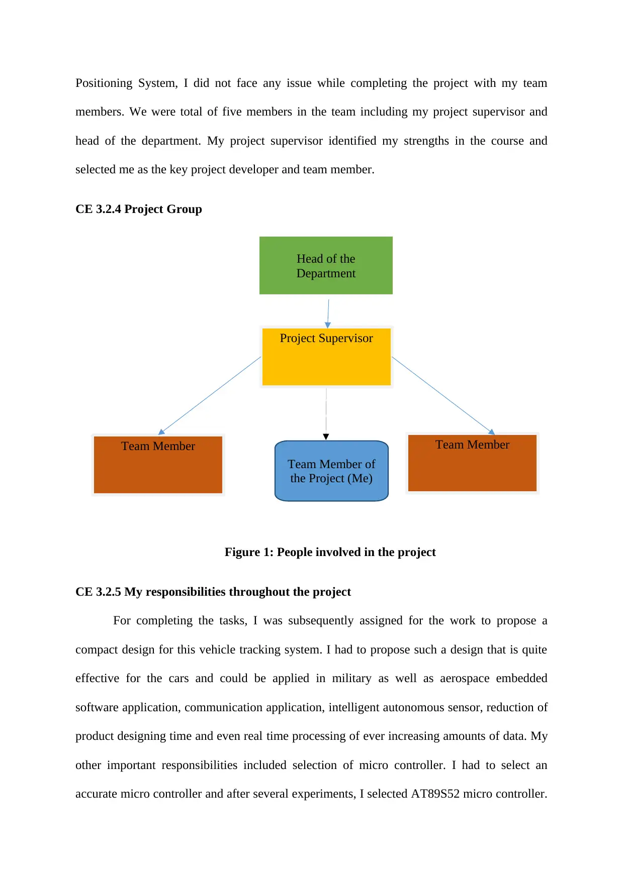
I was being hired as the team member for this specific project of Tracing Down the
Vehicle using GSM and GPS by my project supervisor. Since I had major interest in Global
Project Supervisor
Team Member of
the Project (Me)
Head of the
Department
Team Member Team Member
Positioning System, I did not face any issue while completing the project with my team
members. We were total of five members in the team including my project supervisor and
head of the department. My project supervisor identified my strengths in the course and
selected me as the key project developer and team member.
CE 3.2.4 Project Group
Figure 1: People involved in the project
CE 3.2.5 My responsibilities throughout the project
For completing the tasks, I was subsequently assigned for the work to propose a
compact design for this vehicle tracking system. I had to propose such a design that is quite
effective for the cars and could be applied in military as well as aerospace embedded
software application, communication application, intelligent autonomous sensor, reduction of
product designing time and even real time processing of ever increasing amounts of data. My
other important responsibilities included selection of micro controller. I had to select an
accurate micro controller and after several experiments, I selected AT89S52 micro controller.
⊘ This is a preview!⊘
Do you want full access?
Subscribe today to unlock all pages.

Trusted by 1+ million students worldwide
Moreover, being a master in GPS module, I helped my team members in using the modules
of GPS and GSM. I also had the core responsibility of using C programming language for
software implementation in this project.
CE 3.3 Distinctive Activity
CE 3.3.1 Comprehending the Theory of Project
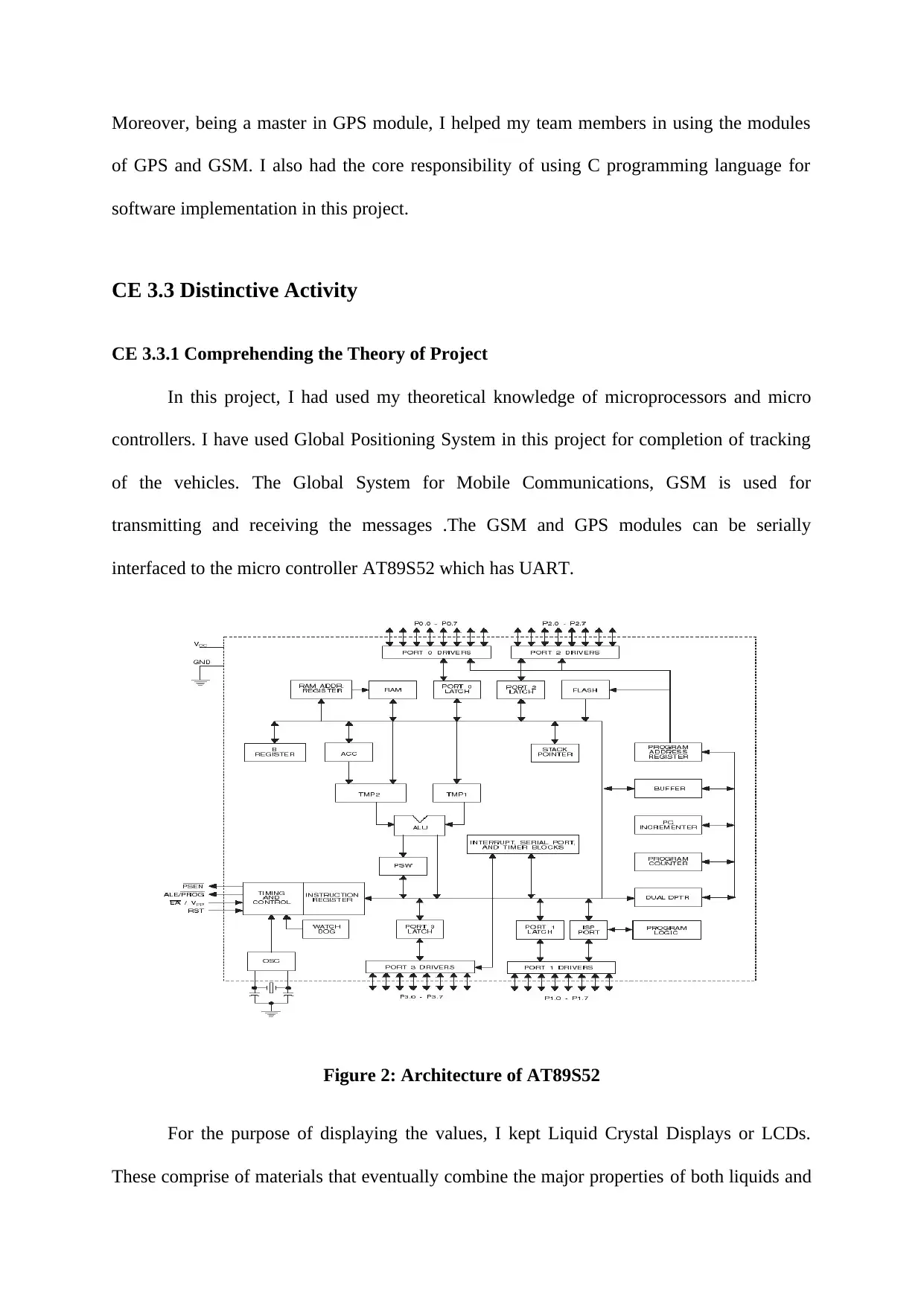
In this project, I had used my theoretical knowledge of microprocessors and micro
controllers. I have used Global Positioning System in this project for completion of tracking
of the vehicles. The Global System for Mobile Communications, GSM is used for
transmitting and receiving the messages .The GSM and GPS modules can be serially
interfaced to the micro controller AT89S52 which has UART.
Figure 2: Architecture of AT89S52
For the purpose of displaying the values, I kept Liquid Crystal Displays or LCDs.
These comprise of materials that eventually combine the major properties of both liquids and
Paraphrase This Document
Need a fresh take? Get an instant paraphrase of this document with our AI Paraphraser
crystals. The working principle of GSM module is used here. There are three divisions of
GSM architecture, which are radio subsystem, network and switching sub system and finally
operating system. The BTS or base transceiver station provided physical connection of
mobile stations to network in form of air interface. For GSM module each and every sub
divided carrier frequency is being sub divided to different time slots with TDMA technique.
Every TDMA frame lasts for 4.164 milliseconds and hence comprises of 8 distinctive time
slots. Every physical channel or time slot in the frame lasts for 577 microseconds and the data
is being transmitted within that time slot in burst form. I easily integrated GSM with
AT89S52 and sent AT commands from microcontroller and received response from module
and displayed it on LCD. In the beginning, we had to connect the GSM with micro controller
for checking whether this module has the capability to work at the TTL logic or it only can
work with RS232. After checking, I ensured that our microcontroller can work with RS232 as
it does not consist of RX and TX (with GND) pins on board. Hence, I had to use MAX 232
IC for connecting serial port to this micro controller.
CE 3.3.2 Engineering knowledge and skills applied in the project
I had correctly applied my understanding of core acquaintance of electronics
engineering. For making the design, I have applied my knowledge of circuit designing, C
programming, micro controllers and microprocessors. Moreover, my intense knowledge in
GPS and GSM modules, helped us in completing the project without any type of
interruptions. Although, I did not have core understanding of KEIL software beforehand,
once the project stated, I attended workshops and took help from my project supervisor and
finally was able to implement it successfully.
CE 3.3.3 Accomplishment and Task Performed
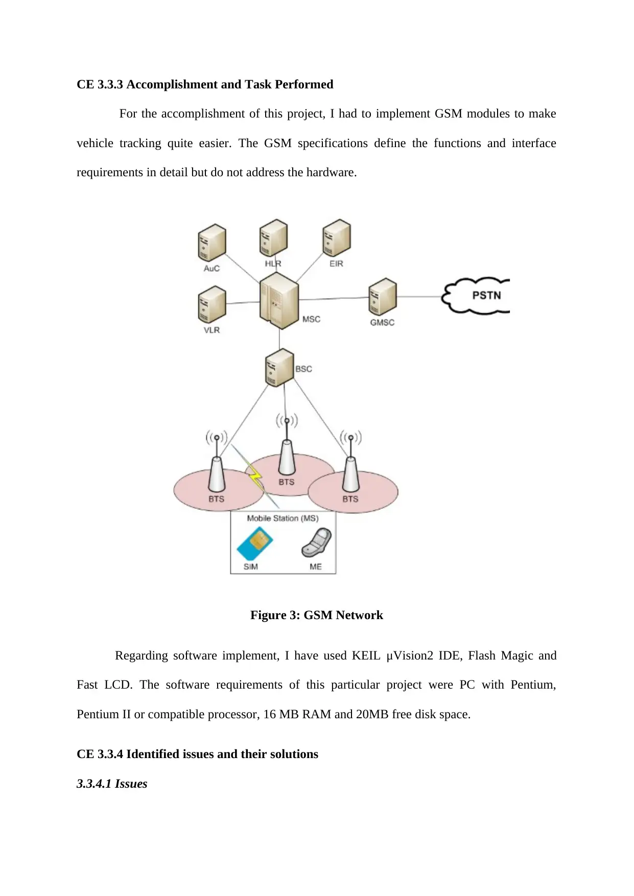
For the accomplishment of this project, I had to implement GSM modules to make
vehicle tracking quite easier. The GSM specifications define the functions and interface
requirements in detail but do not address the hardware.
Figure 3: GSM Network
Regarding software implement, I have used KEIL μVision2 IDE, Flash Magic and
Fast LCD. The software requirements of this particular project were PC with Pentium,
Pentium II or compatible processor, 16 MB RAM and 20MB free disk space.
CE 3.3.4 Identified issues and their solutions
3.3.4.1 Issues
⊘ This is a preview!⊘
Do you want full access?
Subscribe today to unlock all pages.

Trusted by 1+ million students worldwide
One of the problems, which I have confronted within the project was during selection
of micro controller. Previously, I had selected ATmega328 and it was unable to provide
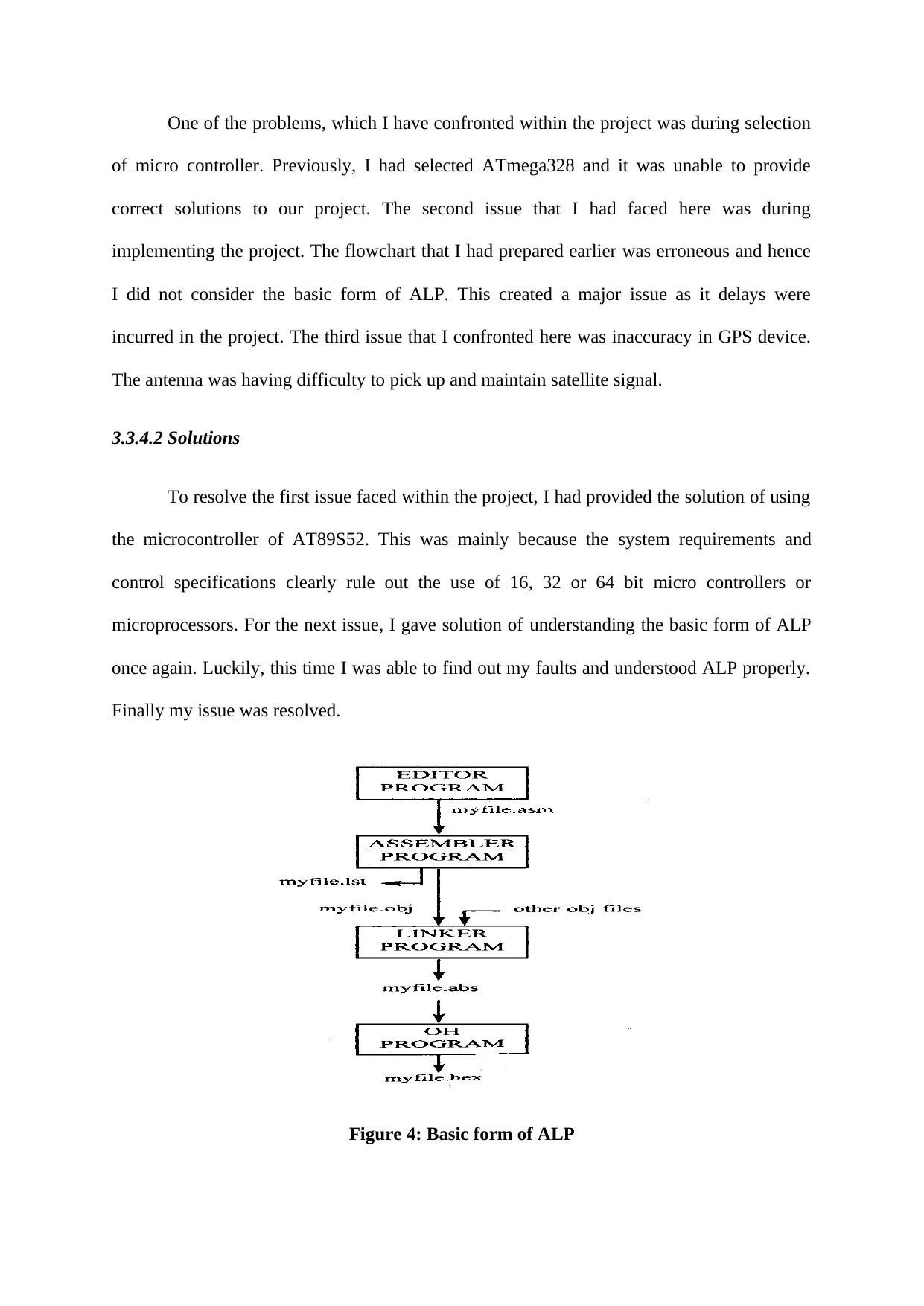
correct solutions to our project. The second issue that I had faced here was during
implementing the project. The flowchart that I had prepared earlier was erroneous and hence
I did not consider the basic form of ALP. This created a major issue as it delays were
incurred in the project. The third issue that I confronted here was inaccuracy in GPS device.
The antenna was having difficulty to pick up and maintain satellite signal.
3.3.4.2 Solutions
To resolve the first issue faced within the project, I had provided the solution of using
the microcontroller of AT89S52. This was mainly because the system requirements and
control specifications clearly rule out the use of 16, 32 or 64 bit micro controllers or
microprocessors. For the next issue, I gave solution of understanding the basic form of ALP
once again. Luckily, this time I was able to find out my faults and understood ALP properly.
Finally my issue was resolved.
Figure 4: Basic form of ALP
Paraphrase This Document
Need a fresh take? Get an instant paraphrase of this document with our AI Paraphraser
For the next issue, I checked that antenna was not properly positioned and hence I
transferred the antenna to a distinct place in which it had clear view of sky.
CE 3.3.5 Plan to produce creative and innovative works
My principal plan was to create the most advanced with the original efforts by
efficiently working with the supervisor of project. I have even sub divided my mechanisms
flawlessly and then considerably made sure that I had accomplished each and every
individual parts with the high efficiency and efficacy.
CE 3.3.6 Collaborative Work
I along with my project supervisor had to complete this project work together. I even
had to test the project functionalities quickly for proper identification of every error within
the project and then accomplished our work easily. Moreover, since KEIL software was new
to us, we took proper trainings from our project supervisor.
CE 3.4 Project Review
CE 3.4.1 Project Overview
I have documented as well as noted each and every result while the integration of my
experiment. I also have used my core understanding of circuit designing to complete the
designing of vehicle tracking system perfectly and appropriately. I have also used KEIL
μVision2 IDE software for the purpose of implementation.
CE 3.4.2 My Contribution to work
I have effectively proposed a compact design for the vehicle tracking system with the
help of GPS and GSM, since I was a responsible team member. My other contribution to this
project was to integrate the entire system effectively and properly. I even provided solution to
the issues faced and utilized KEIL software for implementation of the project.

⊘ This is a preview!⊘
Do you want full access?
Subscribe today to unlock all pages.

Trusted by 1+ million students worldwide
1 out of 9
Your All-in-One AI-Powered Toolkit for Academic Success.
+13062052269
info@desklib.com
Available 24*7 on WhatsApp / Email
![[object Object]](/_next/static/media/star-bottom.7253800d.svg)
Unlock your academic potential
Copyright © 2020–2026 A2Z Services. All Rights Reserved. Developed and managed by ZUCOL.

