A Study on Virtual and Physical Testing Methods Across Industries
VerifiedAdded on 2023/04/24
|70
|14533
|488
Project
AI Summary
This project undertakes a comprehensive comparison of virtual and physical testing methodologies, investigating their application and efficacy across diverse industries. The research employs a mixed-methods approach, including industry surveys and case studies, to evaluate the advantages and limitations of each testing method. The study examines specific components and products within the toy making, hand tools, instrumentation, and PCB fabrication industries, creating virtual testing models using CAD software and comparing their results with physical testing outcomes. The project analyzes factors such as cost, time, accuracy, and the probability of failure to determine the optimal testing approach for different scenarios. Through this analysis, the project aims to provide insights into the evolving landscape of product design, simulation, and manufacturing processes.
ABSTRACT
The main objective of this project was to compare the virtual method of Testing and the
Physical method of Testing. In order to achieve this method of surveying was adopted and a
research was conducted in various industries. On the basis of the data collected some
components being used in the industries were selected the virtual testing models were
made for those components.
While building the models the simulation conditions were made as per the physical
conditions in the industries.
The test results obtained from both the methods of testing were recorded and presented in a
tabular form. The failure stress value and the probability of failure of the product were
obtained using certain statistical tools. Thus the difference between values revealed why in
certain industries physical testing was preferred over virtual testing. The cost tradeoff
analysis was performed at the end to understand the scopes of further penetration of virtual
testing in today’s world.
Paraphrase This Document
Need a fresh take? Get an instant paraphrase of this document with our AI Paraphraser
Table of Contents
Chapter 1: Introduction.............................................................................................................8
1.1Background/problem definition........................................................................................8
1.2Aims and objectives.........................................................................................................8
1.3Methodology.....................................................................................................................9
Hardness Test....................................................................................................................9
Automobile Industry.........................................................................................................10
Fig.1.1 Connecting rod 3D model...........................................................................................11
Chapter 2: Literature Review..................................................................................................13
2.1 Design Industry and its Journey....................................................................................13
2.2 Designing Process and the Product Design.................................................................16
2.3 Product Design and Concurrent Engineering (Kalpakjian & Schmid, 2008)................18
Design for Manufacture, Assembly, Disassembly, and Service...............................19
Environmentally Conscious Design, Sustainable manufacturing.............................19
Selecting Materials....................................................................................................19
Selecting process......................................................................................................19
2.4 Concepts of Product Design used in this Project..........................................................19
2.4.1 General ways in which a certain design is proceeded with....................................19
2.4.2 Factors to consider.................................................................................................20
2.5 CAD...............................................................................................................................25
2.5.1 New Product Development and CAD systems.......................................................25
Chapter 3: Methodology/Procedure/specification..................................................................26
3.1 Industries Surveyed......................................................................................................26
The Toy Making Industry...........................................................................................26
The hand Tools Industry...........................................................................................26
Metrology and the Instrumentation Industry.............................................................26
PCB/ IC Fabrication Industry.....................................................................................27
3.2 Products Selected.........................................................................................................27
3.2.1 Acrylic Bracket........................................................................................................27
3.2.2 Steel Bracket...........................................................................................................27
3.2.3Gripper.....................................................................................................................28
3.2.4 Plier.........................................................................................................................28
3.2.5 Wrench....................................................................................................................28
3.2.6 Spring Balance........................................................................................................28
3.2.7 PCB.........................................................................................................................28
3.3 Approach Followed.......................................................................................................29
3.3.1 Data Collection........................................................................................................29
3.3.2 CAD Modeling.........................................................................................................29
3.3.3 Theoretical Concepts used.....................................................................................29
3.3.4 Virtual testing and its relation with Theoretical Testing..........................................31
3.3.5 Observing Physical Test Results............................................................................31
3.3.6 Trade off (Cost and Time).......................................................................................32
Chapter 4: Designing and Analysis........................................................................................33
4.1 Toy making Industry......................................................................................................33
4.1.1 Steel Bracket...........................................................................................................33
4.1.2 Acrylic Bracket........................................................................................................40
4.1.3 Gripper....................................................................................................................46
4.2 Hand Tools....................................................................................................................54
4.2.1 Plier.........................................................................................................................54
4.2.2 Wrench....................................................................................................................55
4.3 The Instrumentation Industry........................................................................................61
4.3.1 Spring Balance 1....................................................................................................61
4.4 PCB Making Industry....................................................................................................66
4.4.1 Motor Driver PCB for small DC motors...................................................................66
4.4.2 CAD Model..............................................................................................................66
4.4.3 CAE and Analysis...................................................................................................66
Chapter 5: Results and Conclusions......................................................................................68
5 Comparative Studies of the Physical Testing and the Virtual Testing.............................68
5.1 Trade off Cost................................................................................................................69
References.............................................................................................................................71
⊘ This is a preview!⊘
Do you want full access?
Subscribe today to unlock all pages.
Trusted by 1+ million students worldwide
List of Figures
Figure 1- 1.1 Connecting rod 3D model...............................................................................10
Figure 2- Fig.1.2 Connecting rod Vonmisses stress..............................................................11
Figure 3- Fig 2.1.1-A telephone machine used during 90’s. ("WesternElectric302.jpg", 2019)
................................................................................................................................................12
Figure 4- Fig 2.1.2 a sketch showing the variants of a vacuum cleaner (2019)....................14
Figure 5- Fig 4.1. The CAD model of the Steel Bracket.........................................................32
Figure 6- Fig 4.2 Showing the Meshing and Loading on Steel Bracket.................................33
Figure 7- Fig 4.3 Showing the Stress 1..................................................................................33
Figure 8- Fig 4.4 Showing the Stress 2..................................................................................34
Figure 9- Fig 4.5 Showing the Stress 3..................................................................................34
Figure 10- Fig 4.6 Showing the Stress 4................................................................................35
Figure 11- Fig 4.7 Showing the Stress 5................................................................................35
Figure 12- Fig 4.8 Showing the Stress 6................................................................................36
Figure 13- Fig 4.9 Showing the Stress 7................................................................................36
Figure 14- Fig 4.10 Showing the Stress 8..............................................................................37
Figure 15- Fig 4.11 Showing the Stress 9..............................................................................37
Figure 16- Fig 4.12 Showing the Strain..................................................................................38
Figure 17- Fig 4.13 Showing the Deformation in the Bracket................................................38
Figure 18- Fig 4.14 Showing the CAD model of the Acrylic Bracket.....................................39
Figure 19- Fig 4.15 Showing the Material for the Acrylic Bracket..........................................39
Figure 20- Fig 4.16 Showing the Material for the Acrylic Bracket..........................................40
Figure 21- Fig 4.17 Showing the Static Stress 1....................................................................40
Figure 22- Fig 4.18 Showing the Static Stress2.....................................................................41
Figure 23- Fig 4.19 Showing the Static Stress 3....................................................................41
Figure 24- Fig 4.20 Showing the Static Stress 4....................................................................41
Figure 25- Fig 4.21 Showing the Static Stress 5....................................................................42
Figure 26- Fig 4.22 Showing the Static Stress 6....................................................................42
Figure 27- Fig 4.23 Showing the Static Stress 7....................................................................43
Figure 28- Fig 4.24 Showing the Static Stress 8....................................................................43
Figure 29- Fig 4.25 Showing the Static Stress 9....................................................................43
Figure 30- Fig 4.26 Showing the Static Stress 10..................................................................44
Figure 31- Fig 4.27 Showing the Strain..................................................................................44
Figure 32- Fig 4.28 Showing the Deformation.......................................................................45
Figure 33- Fig 4.29 Showing the CAD Model 1......................................................................45
Figure 34- Fig 4.30 Showing the Static Stress 1....................................................................46
Figure 35- Fig 4.31 Showing the Static Stress 2....................................................................47
Figure 36- Fig 4.32 Showing the Static Stress 3....................................................................47
Figure 37- Fig 4.33 Showing the Static Stress 4....................................................................48
Paraphrase This Document
Need a fresh take? Get an instant paraphrase of this document with our AI Paraphraser
Figure 38- Fig 4.34 Showing the Static Stress 5....................................................................48
Figure 39- Fig 4.35 Showing the Static Stress 6....................................................................49
Figure 40- Fig 4.36 Showing the Static Stress 7....................................................................49
Figure 41- Fig 4.37 Showing the Static Stress 8....................................................................50
Figure 42- Fig 4.38 Showing the Static Stress 9....................................................................50
Figure 43- Fig 4.39 Showing the Static Stress10...................................................................51
Figure 44- Fig 4.40 Showing the Strain..................................................................................51
Figure 45- Fig 4.41 Showing the Deformation.......................................................................52
Figure 46- Fig 4.42 Showing the CAD model.........................................................................53
Figure 47- Fig 4.43 Showing the Material of Plier..................................................................53
Figure 48- Fig 4.44 Showing the Principal Stress..................................................................54
Figure 49- Fig 4.45 Showing The Vonmises Stress...............................................................54
Figure 50- Fig 4.46 Showing Principle Strain.........................................................................54
Figure 51- Fig 4.47 Showing CAD model (design lab)...........................................................55
Figure 52- Fig 4.48 Showing material-1.................................................................................55
Figure 53- Fig 4.49 Showing material-2.................................................................................55
Figure 54- Fig 4.50 Showing the Static Stress 1....................................................................56
Figure 55- Fig 4.51 Showing the Static Stress 2....................................................................56
Figure 56- Fig 4.52 Showing the Static Stress 3....................................................................56
Figure 57- Fig 4.53 Showing the Static Stress 4....................................................................57
Figure 58- Fig 4.54 Showing the Static Stress 5....................................................................57
Figure 59- Fig 4.55 Showing the Static Stress 6....................................................................57
Figure 60- Fig 4.56 Showing the Static Stress 7....................................................................58
Figure 61- Fig 4.57 Showing the Static Stress 8....................................................................58
Figure 62- Fig 4.58 Showing the Static Stress 9....................................................................58
Figure 63- Fig 4.59 Showing the Static Stress 10..................................................................59
Figure 64- Fig 4.60 Showing the Strain..................................................................................59
Figure 65- Fig 4.61 Showing the Displacement.....................................................................59
Figure 66- Figure 4.62 Showing the CAD model...................................................................60
Figure 67- Figure 4.63 showing the material- 1.....................................................................60
Figure 68- Figure 4.64 showing the material- 2.....................................................................60
Figure 69- Figure 4.65 the Static Load Stress 1....................................................................61
Figure 70- Figure 4.66 the Static Load Stress 2....................................................................61
Figure 71- Figure 4.67 the Static Load Stress 3....................................................................61
Figure 72- Figure 4.68 the Static Load Stress 4....................................................................61
Figure 73- Figure 4.69 the Static Load Stress 5....................................................................62
Figure 74- Figure 4.70 the Static Load Stress 6....................................................................62
Figure 75- Figure 4.71 the Static Load Stress 7....................................................................62
Figure 76- Figure 4.72 the Static Load Stress 8....................................................................62
Figure 77- Figure 4.73 the Static Load Stress 9....................................................................63
Figure 78- Figure 4.74 the Static Load Stress 10..................................................................63
Figure 79- Figure 4.75 the Static Load Strain........................................................................63
Figure 80- Figure 4.76 the Displacement...............................................................................64
Figure 82- Fig 4.78 the temperature distribution....................................................................65
Chapter 1: Introduction
Figure 80- Figure 4.76 the Displacement...............................................................................64
Figure 82- Fig 4.78 the temperature distribution....................................................................65
Chapter 1: Introduction
⊘ This is a preview!⊘
Do you want full access?
Subscribe today to unlock all pages.
Trusted by 1+ million students worldwide
1.1Background/problem definition
There have been number of instances in the various industries since the time the industrial
revolution has taken place. As we know there has always been an evolutionary process
going contemporary to the development of each and every product with the time and so.
Even the invention of wheel was not done as it appears to be today. The first ever wheel
invented by the humans could have been totally different in shape and size from what we
assume the current structure of the wheel. Similarly the invention of engine which actually
revolutionized the world of machines passed through the same stairs of the evolution. Any
product that we come across in our life and is artificially prepared by human beings in order
to make their life more comfortable has the same story way more or less.
As the products follow the path of evolution with the change in the time and date, the
methods and the processes used to obtain the products have also changed manifolds since
the time the first prototype of any product was made. The method to prepare the fruit juice
today might differ significantly from what it was when the juice was first served to any human
being. The method of preparing a baseball bat is not the same as it was in the ancient times
when the hand tools were used to file and prepare those bats.
Similarly, we have come across one more problem. The point is to check whether the
Physical testing or the virtual testing in the various types of industries pays the better
results. We have to go through the various the surveys done in the different types of the
selected industries which will give us the real time data how those industries are using the
virtual testing and the physical testing depending upon their scopes. Virtual testing is just a
computerized version of the Physical tests done on the various products. For example crash
test done in the automobile industries can be done virtually in the software which have the
results up to some good extent of accuracy. Thus, we have changed the number of the
Physical tests done because there have been certain instances where the results obtained
by the virtual testing have suggested us the parameters to be changed and get the results
quite similar to the expected ones.
1.2Aims and objectives
The aim of this project is to achieve difference between virtual testing and physical testing in
different types of industries. More of industries adopt virtual testing and some of physical
testing. And some adopt both testing for accurate results.
In this project the first objective is to mention the process of virtual and physical testing from
different industry experience. To achieve the process of virtual and physical testing, we will
mention case study of testing process of Four different industries such as Toy Making
industry, Hand Tool Making Industry, Instrumentation Industry and the PCB Fabricating
Industry.
Paraphrase This Document
Need a fresh take? Get an instant paraphrase of this document with our AI Paraphraser
Second objective of our project is to demonstrate a case study of virtual testing where
physical testing used more than virtual testing. In steel industry physical testing are more
preferred compared to virtual testing. In steel industry, firstly making a prototype of project
then test (mechanical, chemical and electrical) all parts of project.
Third objective will conduct a comparison of benefits and limitations for both tests in
designing industry. In conclusion, I will summarize about how companies involved in virtual
method in education like training staff on simulation software to get new specifications of a
product or gain or ability to understand processes.
1.3Methodology
It is very difficult for industries to choose between virtual and physical testing for starting any
project because the selection of virtual and physical prototyping depends upon cost and
time. For virtual prototyping, Industries uses cad software (AutoCAD, Solid works) for
making 3d cad model of project and afterwards it is simulated by simulation software like as
Ansys and Simscale etc.
For physical testing, Industries make a prototype of a project without using any computer
aided designing software. After making the prototype they analyze the mechanical testing
with mechanical instruments such as tensile and compression testing of material with
Universal Testing Machine (UTM) and other testing such as chemical , electrical are
analyzed with their instruments.
Here we will be using the certain examples from the selected industries and will compare
the results obtained from both the Virtual testing and the Physical testing/theoretical testing.
The software that will be used to models the specified component will be Solidworks.
To achieve this goal, I adopt more methodology for both physical and virtual testing and thus
provide an example of my observation in the industry.
Methodology for physical testing in steel industry,
Hardness Test in steel industries,
Hardness is the property of the material which is obtained by putting force on an indenter on
to the surface. The obtained crushing as well the deflection of steel is both elastic and
plastic. Hardness no. is related to ratio of applied load to the surface area of indenter.
The various methods used for hardness testing of any product depend upon its size and
dimensions. For instance- BHN (brinell hardness no.) is obtained by applying load on
spherical area of indenter.
BHN= P / p
π d /2 √ D−d
Where, p= load
D= diameter of ball
d= diameter of indent
Vickers hardness test gives a similar hardness values (VHN) as given by-
VHN= 1.84P/L2
Where L is the diagonal length of indent.
Both hardness values (BHN and VHN) for steel vary with certain limits from 145 to 185.
The point to be noted here is that Rockwell hardness testing is not put in the common use
when structural steel is involved.
Here is my to visit some industries to find out virtual and physical testing analysis-
Automobile Industry- Connecting rod stress analysis
A connecting rod is an engine component that transfers motion from piston to the crank
shaft.
Connecting rod modeling done by Solid works
⊘ This is a preview!⊘
Do you want full access?
Subscribe today to unlock all pages.
Trusted by 1+ million students worldwide
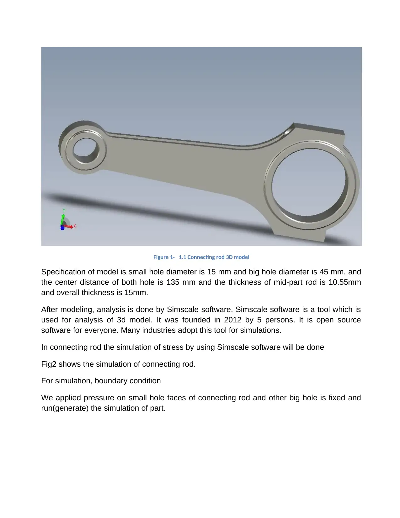
Figure 1- 1.1 Connecting rod 3D model
Specification of model is small hole diameter is 15 mm and big hole diameter is 45 mm. and
the center distance of both hole is 135 mm and the thickness of mid-part rod is 10.55mm
and overall thickness is 15mm.
After modeling, analysis is done by Simscale software. Simscale software is a tool which is
used for analysis of 3d model. It was founded in 2012 by 5 persons. It is open source
software for everyone. Many industries adopt this tool for simulations.
In connecting rod the simulation of stress by using Simscale software will be done
Fig2 shows the simulation of connecting rod.
For simulation, boundary condition
We applied pressure on small hole faces of connecting rod and other big hole is fixed and
run(generate) the simulation of part.
Paraphrase This Document
Need a fresh take? Get an instant paraphrase of this document with our AI Paraphraser
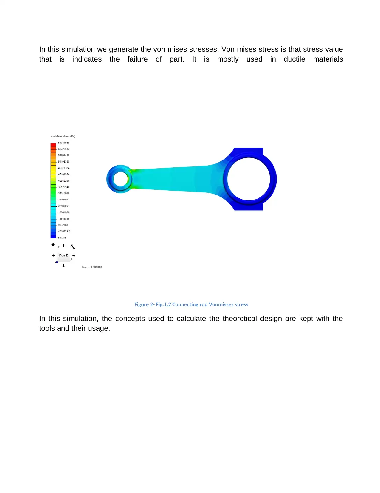
In this simulation we generate the von mises stresses. Von mises stress is that stress value
that is indicates the failure of part. It is mostly used in ductile materials
Figure 2- Fig.1.2 Connecting rod Vonmisses stress
In this simulation, the concepts used to calculate the theoretical design are kept with the
tools and their usage.
that is indicates the failure of part. It is mostly used in ductile materials
Figure 2- Fig.1.2 Connecting rod Vonmisses stress
In this simulation, the concepts used to calculate the theoretical design are kept with the
tools and their usage.
Chapter 2: Literature Review
2.1 Design Industry and its Journey
As we all know that the products developed till now have been imagined prior the
production. The imagination has to get some ways to be put on the physical means to make
it a reality. The design is actually that bridge to give some shape to our imagination. Today,
design industry ("Industrial design", 2019) has become a separate vertical for maximum
industries though it is the part and parcel of the production process. With time there has
been a progress in the thinking and the intellects have been developed to an extent where
even wasting our time in trying to decode our imagination through the frequency of rough
sketches is considered unworthy. There has been a phenomenal journey travelled by the
Human society in almost every aspect of the lifestyle and the lifestyle related products. The
product once used to be the luxury has now become the need of the present scenarios.
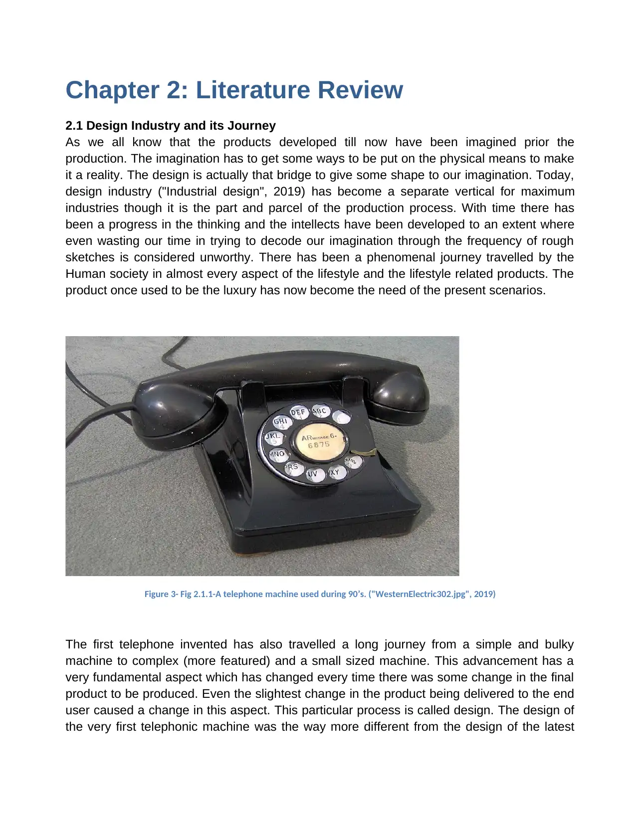
Figure 3- Fig 2.1.1-A telephone machine used during 90’s. ("WesternElectric302.jpg", 2019)
The first telephone invented has also travelled a long journey from a simple and bulky
machine to complex (more featured) and a small sized machine. This advancement has a
very fundamental aspect which has changed every time there was some change in the final
product to be produced. Even the slightest change in the product being delivered to the end
user caused a change in this aspect. This particular process is called design. The design of
the very first telephonic machine was the way more different from the design of the latest
2.1 Design Industry and its Journey
As we all know that the products developed till now have been imagined prior the
production. The imagination has to get some ways to be put on the physical means to make
it a reality. The design is actually that bridge to give some shape to our imagination. Today,
design industry ("Industrial design", 2019) has become a separate vertical for maximum
industries though it is the part and parcel of the production process. With time there has
been a progress in the thinking and the intellects have been developed to an extent where
even wasting our time in trying to decode our imagination through the frequency of rough
sketches is considered unworthy. There has been a phenomenal journey travelled by the
Human society in almost every aspect of the lifestyle and the lifestyle related products. The
product once used to be the luxury has now become the need of the present scenarios.
Figure 3- Fig 2.1.1-A telephone machine used during 90’s. ("WesternElectric302.jpg", 2019)
The first telephone invented has also travelled a long journey from a simple and bulky
machine to complex (more featured) and a small sized machine. This advancement has a
very fundamental aspect which has changed every time there was some change in the final
product to be produced. Even the slightest change in the product being delivered to the end
user caused a change in this aspect. This particular process is called design. The design of
the very first telephonic machine was the way more different from the design of the latest
⊘ This is a preview!⊘
Do you want full access?
Subscribe today to unlock all pages.
Trusted by 1+ million students worldwide
1 out of 70


Your All-in-One AI-Powered Toolkit for Academic Success.
+13062052269
info@desklib.com
Available 24*7 on WhatsApp / Email
![[object Object]](/_next/static/media/star-bottom.7253800d.svg)
Unlock your academic potential
Copyright © 2020–2026 A2Z Services. All Rights Reserved. Developed and managed by ZUCOL.