ENGD3000 Project: Voice Controlled Robot with WiFi Camera
VerifiedAdded on 2022/10/13
|37
|6957
|450
Project
AI Summary
This project details the design and implementation of a voice-controlled robot with a WiFi camera, developed by a student. The robot is controlled via an Android application that transmits voice commands through Bluetooth to an Arduino microcontroller. The project incorporates a DC motor driver, and a power source to enable the robot's movement. The document includes a block diagram, hardware and software specifications, circuit diagrams, and code snippets. The project's methodology involves voice recognition via an Android app, text conversion, Bluetooth communication, and microcontroller processing. The report also covers project planning, resource requirements, and a SWOT analysis, along with results, discussion, and potential future enhancements. The project aims to create a simple, cost-effective, and easily adaptable platform for robotics research and education, focusing on Bluetooth connectivity.
Electronics
Individual Project
Module Code : ENGD3000
PROJECT TITLE : VOICE CONTROLLED ROBOT WITH
WIFI CAMERA
Name of the Student :
Course:
Name of Supervisor :
1
Individual Project
Module Code : ENGD3000
PROJECT TITLE : VOICE CONTROLLED ROBOT WITH
WIFI CAMERA
Name of the Student :
Course:
Name of Supervisor :
1
Paraphrase This Document
Need a fresh take? Get an instant paraphrase of this document with our AI Paraphraser
Abstract
In this project, a voice-controlled personal assistant Robot has been designed. The
robot is capable of taking the human voice commands from the mobile app. It can take
the instructions and run them. It also provides a message using the sound signal. The
project is designed using a micro- controller related system. The performance can be
evaluated by obtaining good results of the starting experiments. Some better practices
are also studied involving some uses in the houses, medical treatment, cars and
industrial areas.
In the system discussed here, a speech recognition system is not needed for the
recognition of the human voice for controlling the robot. In the system used, an android
application has been used for the recognition as well as the processing of a person’s
sound that can be next converted to textual format ( using the speech to text converter
for this purpose ). The textual data can be moved towards the robot by the use of a
Bluetooth device. The textual data can be further altered and studied using the
microcontroller for controlling the robot accordingly. The purpose of this task is the
development of a simple robot hardware architecture having strong computing devices
so that the designer of the robots can pay attention on the research and studies and not
on the Bluetooth connection study. The students can also very effectively use the system
to carry out various experiments for the study of small applications of the system. It is
not very costly and very easy for using also.
2
Acknowledgements
3
3
⊘ This is a preview!⊘
Do you want full access?
Subscribe today to unlock all pages.
Trusted by 1+ million students worldwide
Contents
Abstract........................................................................................................................................2
Acknowledgements......................................................................................................................3
Introduction.................................................................................................................................5
Background..............................................................................................................................5
Aims & Objectives....................................................................................................................5
Project Specification.................................................................................................................5
BLOCK DIAGRAM..........................................................................................................................8
Literature Research & Background Information...........................................................................9
Specification and Design............................................................................................................10
Details of Hardware requirements.........................................................................................11
Project Experiment or design Specification................................................................................17
Planning of the project...........................................................................................................17
Designing of the project:........................................................................................................18
Finalising the block diagram...................................................................................................18
Hardware and software requirments:....................................................................................18
Purchasing of the parts:.........................................................................................................18
Assembly and trial run:...........................................................................................................18
Code.......................................................................................................................................18
Real Time Progress.................................................................................................................22
Project Management..................................................................................................................25
GANTT Chart:.........................................................................................................................26
PERT Chart:.............................................................................................................................27
SWOT analysis:.......................................................................................................................28
Results and Discussion...............................................................................................................29
Future Work...............................................................................................................................29
Conclusions................................................................................................................................31
References.................................................................................................................................32
4
Paraphrase This Document
Need a fresh take? Get an instant paraphrase of this document with our AI Paraphraser
Introduction
Background
The project is to design a system with a robot that is capable of receiving the
commands using Bluetooth and working as per the instructions and also to design an
android application that allows a user to send the commands by using Bluetooth. The
robot is to be fitted with an Arduino UNO which is a microcontroller which on
receiving the command received via the Bluetooth and controls the driver motor. At first
stage the skeleton of the project was designed which was based on my research and
many related videos. After finalising the design the basic structure of my project was
designed. An andriod phone is to be used to input the command. The Bluetooth system
has to be used for receiving the command from the Android phone and for transmitting
the command towards the micro controller, which inturn drives the driver motor. After
studying about the circuits and based on my requirements of the working methodolody
of the robot the following block diagram was finalised.
Aims & Objectives
Controlling a moving object by voice is gaining more and more application. A super
market trolly controlled by voice is a popular example. This eliminates the need for the
buyer from pushing the trolly along with them. The buyer can just command the trolley
to follow them by voice control. In this project, we tried to control the movement of a
supermarket trolley with voice.
Project Specification
The trolley is fitted with wheels and DC motor driver. The blue tooth module fitted to
the trolley receives the voice from the buyer and feeds to the Aurdino micro controller.
The trolley is made to receive signals from the buyer for forward, reverse, left and right
movement. The driver of the motor is connected to the Ardunio controller. The DC
motors ( 2 ) are being employed for moving the trolley in various directions like the
5
forward, reverse, left or right direction. A 9V battery can be employed for powering the
motor driver in order to drive the motors.
The chosen task is the design of a system using a robot which can be controlled using
both voice signal and smart phone APP. In this project, a robot is built which is capable
of receiving a command using bluetooth and working as per the coommands. The
android application is developed that lets the user send the commands using a bluetooth
device. The Commands are interpreteded using a bluetooth modem which is attached to
Arduino UNO. The Arduino can control the motor that allows the movements of the
robot.
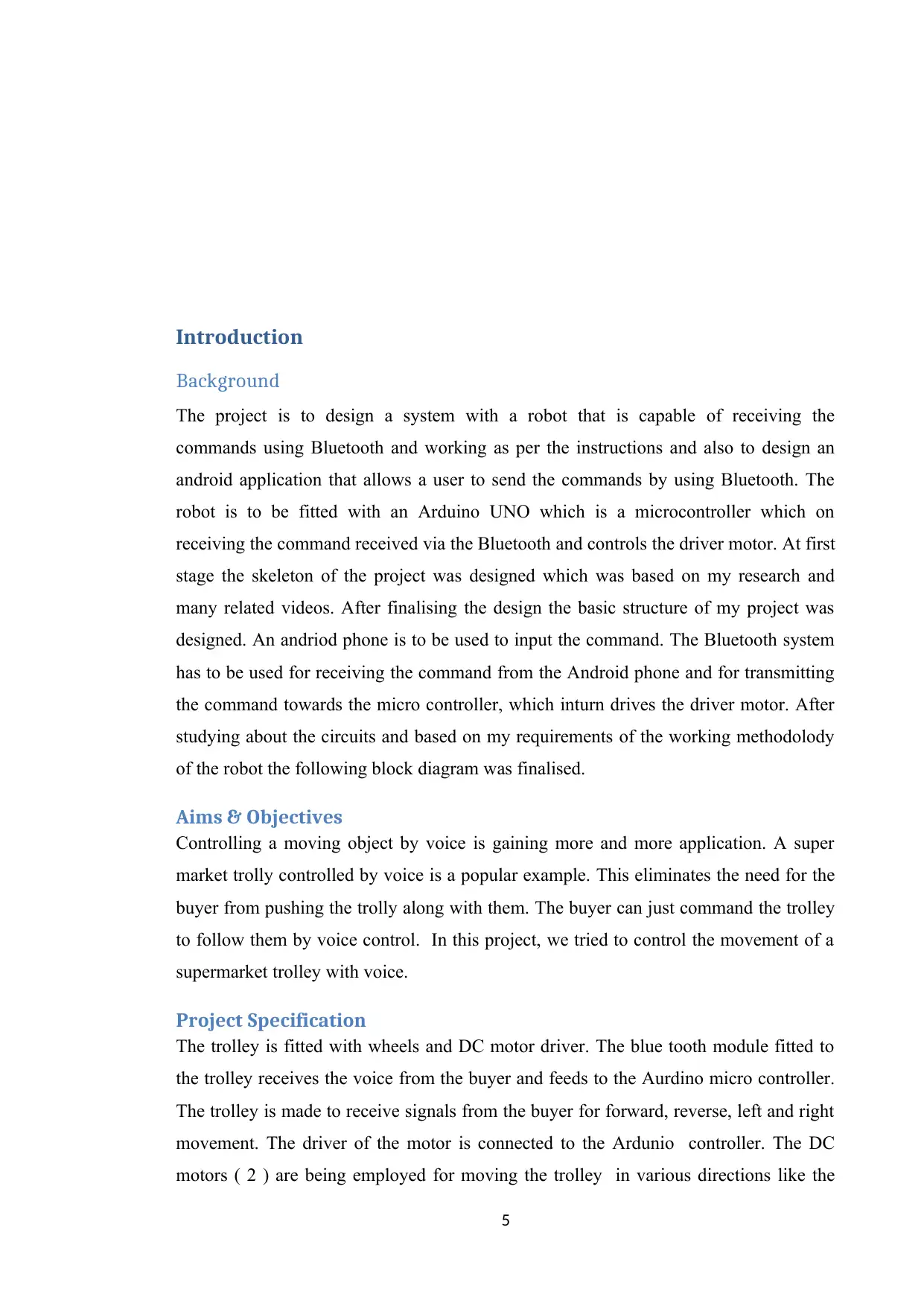
An example of a voice controlled robot is depicted in figure 1.
6
motor driver in order to drive the motors.
The chosen task is the design of a system using a robot which can be controlled using
both voice signal and smart phone APP. In this project, a robot is built which is capable
of receiving a command using bluetooth and working as per the coommands. The
android application is developed that lets the user send the commands using a bluetooth
device. The Commands are interpreteded using a bluetooth modem which is attached to
Arduino UNO. The Arduino can control the motor that allows the movements of the
robot.
An example of a voice controlled robot is depicted in figure 1.
6
⊘ This is a preview!⊘
Do you want full access?
Subscribe today to unlock all pages.
Trusted by 1+ million students worldwide
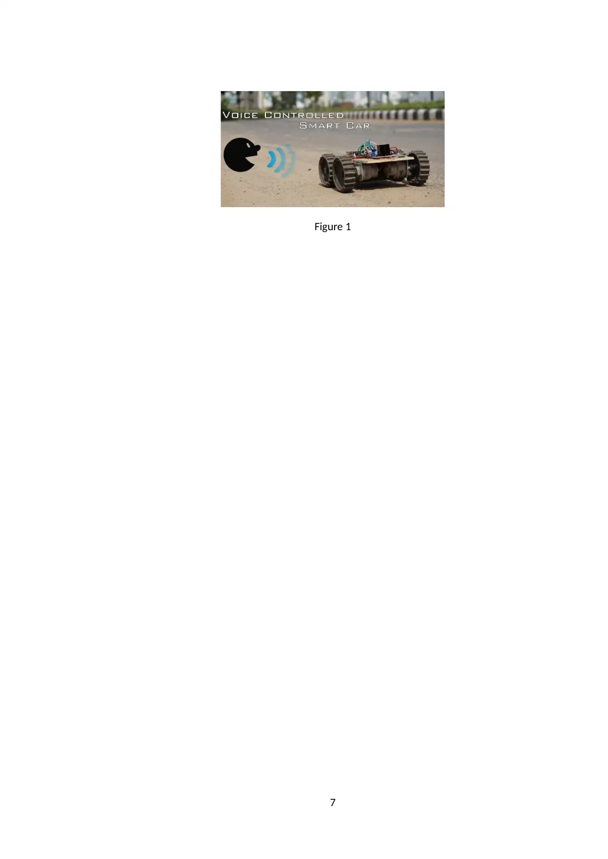
Figure 1
7
7
Paraphrase This Document
Need a fresh take? Get an instant paraphrase of this document with our AI Paraphraser
BLOCK DIAGRAM
Figure 2
Figure 3
8
MOBILE APP
CONTROLLING
DC MOTORS
WIFI CAMERA
L293D MOTOR DRIVER
POWER SOURCE
ARDUINO UNO
ATMEGA 328
BLUETOOTH
HC-05
Figure 2
Figure 3
8
MOBILE APP
CONTROLLING
DC MOTORS
WIFI CAMERA
L293D MOTOR DRIVER
POWER SOURCE
ARDUINO UNO
ATMEGA 328
BLUETOOTH
HC-05
Literature Research & Background Information
A voice controlled robotic system can be designed using an Arduino microcontroller.
Such a system can be used at the places where human entry is full of risk. An android
device can be used to control the robot using voice commands. A Bluetooth module can
be used for capturing and reading the voice commands. The operation of the robot
depends on the commands got from the android device used [ 1 ].
An android application can be used to transmit the data. The receiver can read these
commands and interpret them to control the robot. The commands for the movement of
the robot can be sent by an android device. Arduino microcontroller can be used for the
operation of the motor for movement of the robot when a command is received. Serial
communication is used between the receiver and the android device. A wireless camera
can also be interfaced to the Arduino microcontroller. A detector can be used for the
protection from obstacles ( by using ultrasonic sensor ).
Today, almost all the work is being done by the help of a robot or a robotic arm which
has some degrees of freedom depending on the application. If a wireless robotic arm is
designed which has vision and is gesture controlled, then 3 parts are needed. They are
the accelerometer, robotic arm and a platform. The robotic arm can be controlled using
a system based on accelerometer by the help of RF signals. An accelerometer can be
attached to a person’s hand which can capture the hand’s motion. The movement of the
robotic arm takes place according to the hand’s movements. The next accelerometer can
be attached to the person’s leg which helps in the movement of the platform. The
various movements which can be included are : pick and place, pick and drop, raise and
lower the object, forward, backward, right and left movement. An IP based camera can
be used for real time video streaming ( in mobile or laptop ) which is wireless [ 2 ].
A voice controlled robot shows the movements which can be controlled by a user using
some voice commands [ 3 ]. Zigbee module can be used for the transmission of the
digital signals [ 18 ] [ 19 ]. Servo motors can be used in the system designed using the
robots.
A vision based gesture recognition system can be easily implemented [ 6 ]. The motion
capture sensor recognition can be implemented using Arduino. A finger gesture
9
⊘ This is a preview!⊘
Do you want full access?
Subscribe today to unlock all pages.
Trusted by 1+ million students worldwide
recognition system based on the active tracking mechanism can be implemented [ 8 ].
The gestures can be recognised using the acceleration data using ANNs ( Artificial
Neural Networks ) [ 9 ] [ 10 ] [ 11 ]. For the transmission and reception of any message
signal, an encoder and a decoder circuit is needed with the transmitter and the receiver
circuit [ 12 ]. The accelerometer can be easily interfaced with the microcontroller [ 13 ].
The smart phone camera can be used for the real time video stream [ 15 ]. The IP based
Android application can be used for the transmission of real time video using a wireless
connection [ 16 ].
The method followed is : Initially the board was fitted with 4 DC motors and the
wheels. The wheels were ensured that they are not tightly fitted and not gripping. All
other parts were assembled on the board as shown in the following circuit diagram.
The motor driver and the Bluetooth module was also fitted in the board. The pin
diagram of the motor driver is as shown in the following picture.
The android app is used for phones having an android based operating system. It can be
downloaded using the android app Market that is already present in all the android
phones.
The Android platform also provides the support for the Bluetooth network stack, that
allows a device to exchange data with other Bluetooth devices over a wireless mode.
The application framework can provide access to the Bluetooth functionality using the
Android Bluetooth APIs.
Once the assembly activity was completed, a trail run was carried out. Following
obstacles were observed.
It was observed that the command from the android phone was not received by the
Bluetooth module. Suitable modifications were carried out, to sort out the connectivity
issue.
The wheels were not rotating smoothly. The screws used for fitting the wheel to the
shaft of the DC motor were loosened to correct this problem.
The robot was moving very slowly. This was due to the insufficient power received by
the motor driver. A new battery with higher capacity was purchased and fitted.
10
Paraphrase This Document
Need a fresh take? Get an instant paraphrase of this document with our AI Paraphraser
The Robot was only moving in the forward and reverse direction. The robot was seen
struggling to turn left and right. Wheel movement matrix planned in the initial stage of
the project allowed rotation of left side wheels when making the right turn. The right
side wheels were not rotating. This matrix was modified to allow the right side wheels
to rotate anticlockwise, while the left side wheels were rotating clockwise. This change
has enabled the robot to turn left or right easily.
Suitable modifications to tackle the above listed problems were made and a rerun of the
trail was underataken and found the robot was working as expected. The following
picture/video shows how the robot was moving and responding to the commands given.
The Arduino based educational mobile robots can be easily integrated in Robot
Operating System [ 26 ]. This makes the design of the system very easy using an
Arduino microcontroller. Arduino is the first open source hardware and software
computer company which designs and uses development boards which are based on
microcontrollers [ 27 ]. The main reason for the use of Arduino Uno is that it is open
source and does not involve any associated cost. With the introduction of Arduino
which is an open source platform, the Do It Yourself projects in the field of electronics
have become easier to implement [ 28 ]. Any alterations can be made to the design with
minimum efforts and that too the students can implement themselves. This has made the
project designing very easy. Now a days, open source hardware is becoming significant
for research activities [ 29 ]. Many researchers are also using Arduino for their research
work. Arduino board can be used as a tool to study and in research work [ 30 ].
Arduino is a type of microcontroller which is very simple to use and has a large number
of sensors as well as libraries which help to enhance its capabilities [ 31 ]. The sensors
are very simple to interface with the Arduino microcontroller. There are many examples
where efficient systems have been designed using Arduino. Some of them are discussed
here. A weather monitoring station can be designed using Arduino for data collection
[ 32 ]. The various parameters used in weather monitoring are the temperature,
humidity, etc. which can be sensed using a sensor and then reported in a presentable
manner. A temperature sensor and a humidity sensor can be used for the purpose of
measuring the parameters. A cost effective and energy efficient smart drip irrigation
system can be designed using raspberry pi and arduino [ 33 ]. A low cost intelligent
smart home automation and security system can be designed using Arduino and Wi – Fi
[ 34 ]. In a smart home, various sensors can be installed which read various parameters
11
and then take an action accordingly. A heart rate monitoring system can be designed
through finger tip by using arduino and a processing software [ 35 ]. This shows that
various types of systems can be designed using Arduino microcontroller. The Wi – fi
module can also be interfaced and android app be merged into the system.
By the help of Bluetooth profile as well as android platform architecture different types
of Bluetooth applications can be designed.
The HC-05 Bluetooth Module is a type of class-2 Bluetooth module having Serial Port
Profile that can be configured as a Master or a Slave. It can be used mainly for serial
port replacing in order to create a connection between the MCU, PC to the embedded
system.
The Bluetooth protocol is the Bluetooth Specification v 2 . 0 + EDR. A value of
Frequency of 2.4 GHz is used in ISM band. The Modulation scheme used is the GFSK (
Gaussian Frequency Shift Keying ). The value of the Emission power is less than or
equal to 4 dBm and belongs to Class 2. The value of Sensitivity is not more than -84
dBm at 0.1% BER ( Bit Error Rate ). The Speed for an Asynchronous system is
2.1Mbps ( Max ) to 160 kbps and for the Synchronous system it is 1Mbps. For the
purpose of security, authentication and encryption are used. The profiles used is the
Bluetooth serial port. The Power supply used is +3.3VDC at 50mA. The working
temperature is -20 to +75 Centigrade. The Dimension is 26.9mm x 13mm x 2.2 mm.
Some project management techniques can be applied to the design. GANTT chart was
used to initially estimate the time frame required to complete the project, to sequence
the activities and to identify major milestones along the way. Regular updation of the
activities completed in the LOG BOOK can enable to check the progress of the project
inline with the time estimate originally envisaged. The achievement of major milestones
motivated me to complete the project on time.
Specification and Design
The following are the hardware parts required.
12
⊘ This is a preview!⊘
Do you want full access?
Subscribe today to unlock all pages.
Trusted by 1+ million students worldwide
1 out of 37
Related Documents


Your All-in-One AI-Powered Toolkit for Academic Success.
+13062052269
info@desklib.com
Available 24*7 on WhatsApp / Email
![[object Object]](/_next/static/media/star-bottom.7253800d.svg)
Unlock your academic potential
Copyright © 2020–2026 A2Z Services. All Rights Reserved. Developed and managed by ZUCOL.