ME405 Thermal Systems Design Project 1: Steam Turbine Analysis

Verified

Added on  2020/03/16

|7
|603
|61
Project
AI Summary
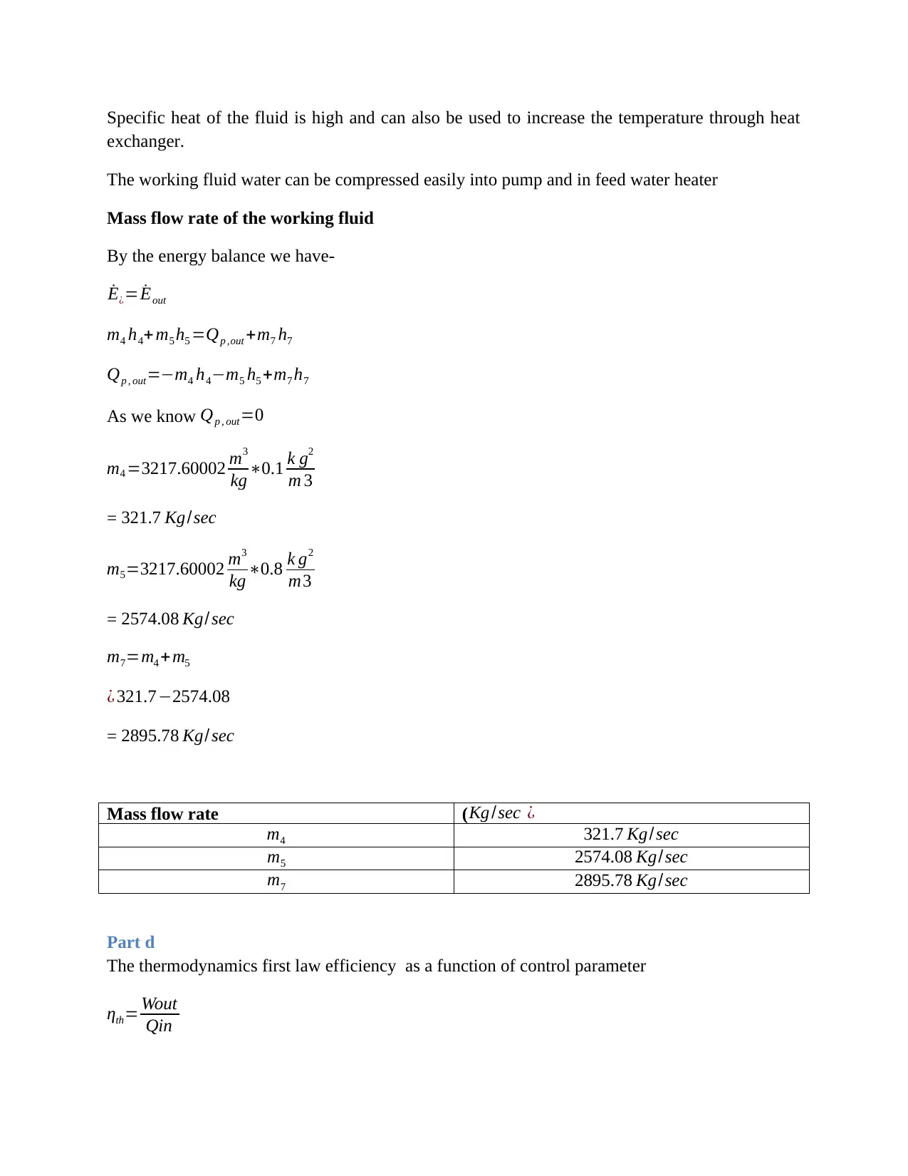
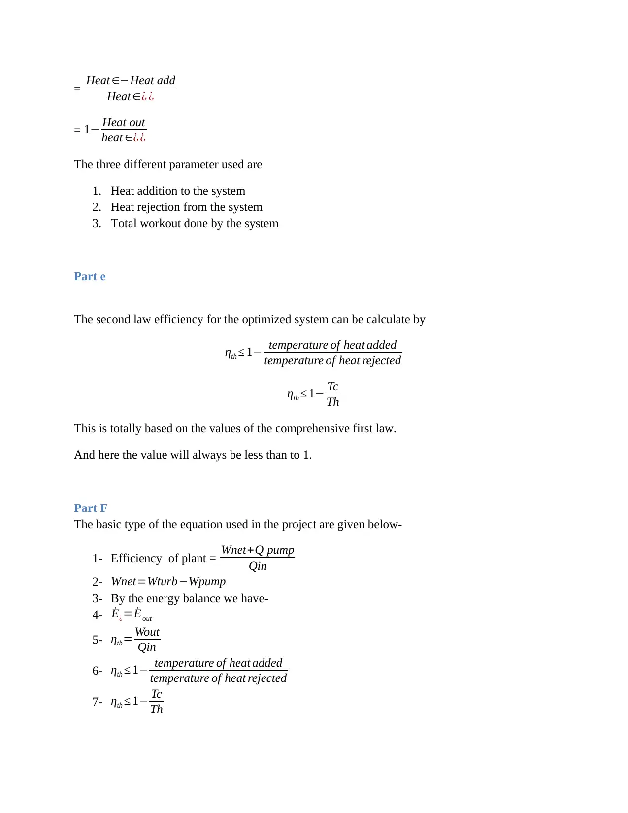
This document presents a comprehensive solution for Project 1 in ME405: Thermal Systems Design at Washington State University, focusing on a steam turbine power plant with steam reheat and regenerative co-generation. The project addresses the design of a system that meets specific constraints, including a thermal efficiency target above 45% and combustion efficiency of 88%. The solution includes system diagrams, T-s diagrams, and detailed calculations of turbine work, plant efficiency, and mass flow rates. It also covers the design of a co-generation plant, fluid properties, and the application of the first and second laws of thermodynamics. Furthermore, the document analyzes various parameters affecting efficiency and references relevant research papers. This project demonstrates a thorough understanding of thermal system design principles and practical application in power plant engineering.
Document Page
ME405: Thermal Systems Design
Washington State University Project 1 (Final Report Due:
October 9, 2017)
Solution
Given:
Steam turbine power plant is working on steam reheat – regenerative co-generation for the
consumption of electricity and water.
Maximum demand- 20 MW
Volume of hot water demand weekdays - 850,000 gallons = 3217.60002m3
Design constraints
The thermal efficiency of the system should be higher than 45%
Combustion efficiency = 88%
All the pumping energy should come from the turbine work.
Temperature of the hot water = 185
Turbine isentropic efficiency = 93 %
Answers
Part a
The system block of the steam turbine power plant are given below
tabler-icon-diamond-filled.svg

Paraphrase This Document

Need a fresh take? Get an instant paraphrase of this document with our AI Paraphraser
Document Page
Figure 1: System diagram
The T-s diagram of the system are given below-
Figure 2: T-s diagram
Part b
The basic analysis of the system are given below-
Document Page
work done by pump1+ pump 2=v8 ( P9P8 ) + v8 ( P10P7 )
= 3217.60002 m3
kg ( 70005)+ 3217.60002 m3
kg ( 5900110 )106+ 15MW
= 51.13 MW
For the given temperature and pressure, the value of the specific enthalpies are given below-
h1=h2=h3 =h4 =3009.31 KJ
kg
Based on the values obtained from steam table
h4=3423.34 KJ
kg
h5 =3434.34 KJ
kg
h6 =3447.34 KJ
kg
h7 =hf @ 500 KPa=645.34 KJ
kg
h8 =hf @ 5 KPa=122.17 KJ
kg
h9=h8 +Wpump 1=129 . 45 KJ
kg
h10=h8 +Wpump 2=45 .17 KJ
kg
W turbine 1 = 3217.60002 m3
kg ( 1233.21211.0 )106
= 71.430 MW
W turbine 2 = 3217.60002 m3
kg ( 645.341 22.17 )106
= 16.83 MW
W turbine 3 = 3217.60002 m3
kg ( 129.4545.17 )106
Document Page
= 0.27 MW
Total work done by turbine = 71.43+16.83+0.27
= 88.53 MW
Wnet=WturbWpump
= 88.5351.13
= 37.4 MW
Qin heat addition=20 MW ( total heat added ) +57.93 MW (heat adde d¿ pump )
= 77.93 MW
Efficiency of plant = Wnet+Q pump
Qin
= 37.4 +0
77.93
= 47.99 %
From the above calculation shows that by using three turbine in the system given efficiency as
47.99%.
Part c
The basic design of the co-generation plant for this purpose can be seen below-
Figure 3: Co-generation plant
Fluid properties
Water is considered as the working fluid
tabler-icon-diamond-filled.svg

Paraphrase This Document

Need a fresh take? Get an instant paraphrase of this document with our AI Paraphraser
Document Page
Specific heat of the fluid is high and can also be used to increase the temperature through heat
exchanger.
The working fluid water can be compressed easily into pump and in feed water heater
Mass flow rate of the working fluid
By the energy balance we have-
˙E¿= ˙Eout
m4 h4+ m5 h5 =Qp ,out +m7 h7
Qp , out=m4 h4m5 h5 +m7 h7
As we know Qp , out=0
m4 =3217.60002 m3
kg 0.1 k g2
m 3
= 321.7 Kg/sec
m5=3217.60002 m3
kg 0.8 k g2
m3
= 2574.08 Kg/ sec
m7=m4 +m5
¿ 321.72574.08
= 2895.78 Kg/ sec
Mass flow rate ( Kg /sec ¿
m4 321.7 Kg/sec
m5 2574.08 Kg/sec
m7 2895.78 Kg/sec
Part d
The thermodynamics first law efficiency as a function of control parameter
ηth= Wout
Qin
Document Page
= Heat Heat add
Heat ¿ ¿
= 1 Heat out
heat ¿ ¿
The three different parameter used are
1. Heat addition to the system
2. Heat rejection from the system
3. Total workout done by the system
Part e
The second law efficiency for the optimized system can be calculate by
ηth 1 temperature of heat added
temperature of heat rejected
ηth 1 Tc
Th
This is totally based on the values of the comprehensive first law.
And here the value will always be less than to 1.
Part F
The basic type of the equation used in the project are given below-
1- Efficiency of plant = Wnet+Q pump
Qin
2- Wnet=WturbWpump
3- By the energy balance we have-
4- ˙E¿= ˙Eout
5- ηth= Wout
Qin
6- ηth 1 temperature of heat added
temperature of heat rejected
7- ηth 1 Tc
Th
Document Page
References
Gigliucci, G., Petruzzi, L., Cerelli, E., Garzisi, A. and La Mendola, A., 2004. Demonstration of a
residential CHP system based on PEM fuel cells. Journal of power sources, 131(1), pp.62-68.
Agashichev, S.P., 2004. Analysis of integrated co-generative schemes including MSF, RO and
power generating systems (present value of expenses and “levelised” cost of
water). Desalination, 164(3), pp.281-302.
Grillo, O., Magistri, L. and Massardo, A.F., 2003. Hybrid systems for distributed power
generation based on pressurisation and heat recovering of an existing 100 kW molten carbonate
fuel cell. Journal of Power Sources, 115(2), pp.252-267.
Gribaudo, M., Horváth, A., Bobbio, A., Tronci, E., Ciancamerla, E. and Minichino, M., 2002.
Model-checking based on Fluid Petri Nets for the temperature control system of the ICARO co-
generative plant. Lecture notes in computer science, 2434, pp.273-283.
chevron_up_icon
1 out of 7
circle_padding
hide_on_mobile
zoom_out_icon
[object Object]