Wastewater Treatment Plant Design Project - Environmental Engineering
VerifiedAdded on 2022/08/11
|64
|10032
|28
Project
AI Summary
This project presents a comprehensive design for a wastewater treatment plant, specifically targeting a population of 200,000 in the UK. The project begins with an abstract that outlines the key objectives: designing a screen bar, a grit removal tank, and an oil and grease removal tank. The methodology includes a process flow diagram, mass balance calculations, and mechanical designs for the screen bar and grit removal tank. The catenary bar screen was chosen due to its cost-effectiveness and the aerated grit and grease removal tank was selected due to its ability to handle large volumes of wastewater. The physical dimensions of the screen bar and grit tank were estimated, along with the design of ancillary equipment like an influent pump and a waste collection tank. The project also includes piping and instrumentation diagrams (P&ID) for both the screen and grit tank, as well as calculations for mass balance, mechanical design, and equipment sizing. A risk assessment and a What-If analysis are also included, highlighting potential hazards and operational considerations within the plant.
Contents
Abstract................................................................................................................................................1
1.0 Introduction...................................................................................................................................2
2.0 Aims and Objectives......................................................................................................................2
3.0 Process Flow Diagram...................................................................................................................3
4.0 Mass Balance..................................................................................................................................3
5.0 Mechanical Design.........................................................................................................................5
5.1 Bar Screen..................................................................................................................................5
5.1.1 Screen Selection..................................................................................................................5
5.1.2 Design of Catenary Bar Screen..........................................................................................9
5.2 Grit Removal Tank..................................................................................................................12
5.2.1 Selection of Grit Removal Tank and Oil Removal Tank...................................................12
5.2.2 Design of Aerated Grit Chamber.........................................................................................13
5.3 Sizing of Pipes..............................................................................................................................16
6.0 Piping and Instrumentation Diagram (P&ID)...........................................................................17
6.1 Catenary Screen.......................................................................................................................17
6.2 Aerated Grit Tank...................................................................................................................18
7.0 Start-up and Shutdown and Aerated Grit Chamber................................................................20
8.0 Ancillary Equipment...................................................................................................................21
8.1 Influent Pump..........................................................................................................................21
8.2 Waste Collection Tank............................................................................................................22
Appendix (1): Mass balance Calculations........................................................................................24
1
Paraphrase This Document
Need a fresh take? Get an instant paraphrase of this document with our AI Paraphraser
A1.1 Mass balance of Grit Tank (T-102)......................................................................................28
Appendix (2): Mechanical Design calculations................................................................................29
A2.1 Calculations of Catenary bar screen Design............................................................................29
A2.2 Calculations of Aerated Grit Chamber Design...................................................................31
A2.3 Calculations of Oil and Grease Tank..................................................................................33
Appendix (3): Standard Size of carbon Steel Pipe and Calculations....................................................37
Appendix (4): Ancilary Equipment Calculations............................................................................38
A4.1 the Influent Pump....................................................................................................................38
A4.2 Waste Collection Tank (T-111)...............................................................................................39
Reference............................................................................................................................................40
List of figures
Figure 1: The process flow diagram of the designed part of the wastewater treatment plant (Replace
PFD).....................................................................................................................................................5
Figure 2:The classification of used Screens in wastewater treatment as preliminary stage (Metcalf
& Eddy, 2014).......................................................................................................................................8
Figure 3: four main types of mechanically cleaned coarse screen: Chain-driven screen, reciprocating
rake, catenary screen, and continues belt (Qasim, 2017)....................................................................11
Figure 4: Piping and instrumenting Diagram (P&ID) of Catenary Screen (Replace)........................20
Figure 5: Piping and instrumenting Diagram (P&ID) of aerated grit tank (Replace).....................21
Figure 6: The consumption water per capita per one day in 2018 : (Warner et al., 2019).................27
List of tables
Table 1: The summary of the mass balance of the first part of wastewater treatment plant..............6
Table 2: The advantages and disadvantages of types of mechanically cleaned coarse screen
(Metcalf & Eddy, 2014)........................................................................................................................8
Table 3: The summary of result of bar screen design.......................................................................13
Table 4: The comparison of vortex and aerated grit chambers (Metcalf & Eddy, 2013; EPA, 2003). 14
Table 5: The summary of result of design of aerated grit removal tank...........................................17
2
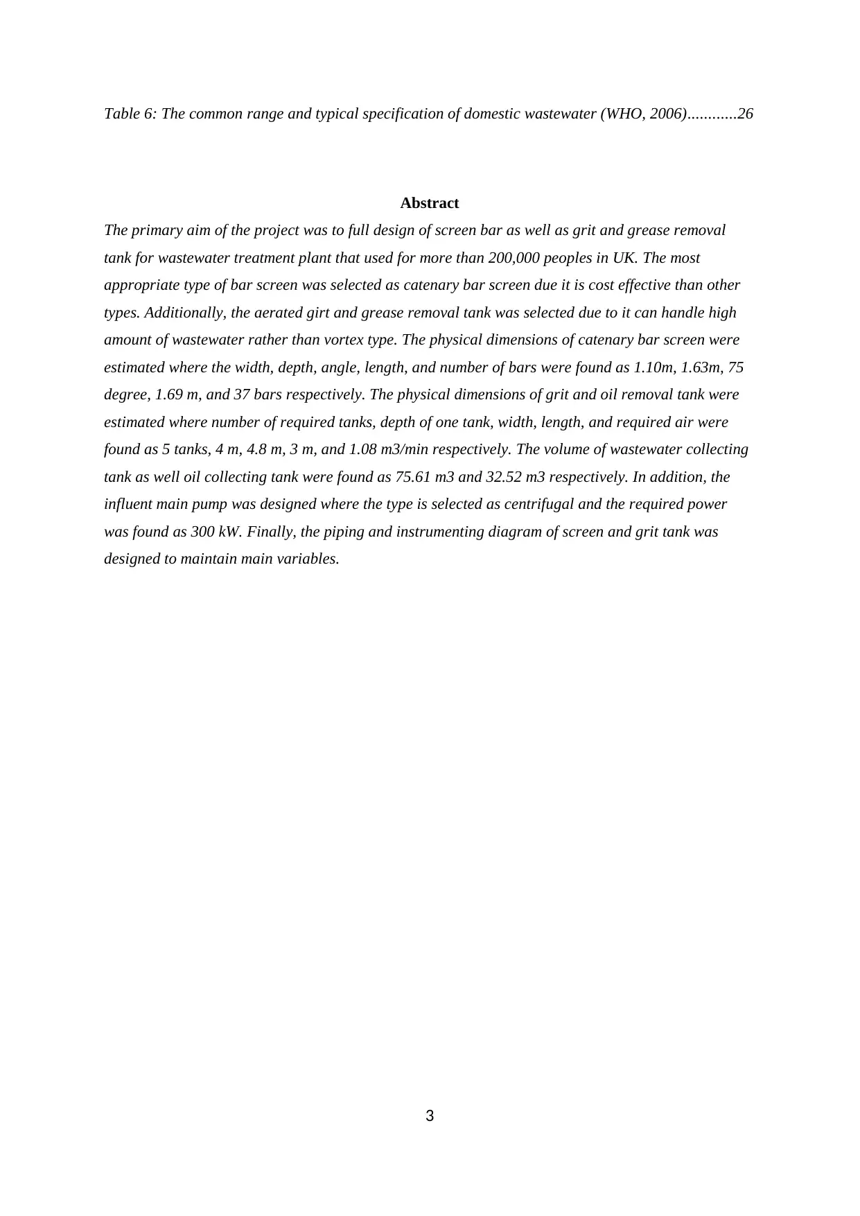
Table 6: The common range and typical specification of domestic wastewater (WHO, 2006)............26
Abstract
The primary aim of the project was to full design of screen bar as well as grit and grease removal
tank for wastewater treatment plant that used for more than 200,000 peoples in UK. The most
appropriate type of bar screen was selected as catenary bar screen due it is cost effective than other
types. Additionally, the aerated girt and grease removal tank was selected due to it can handle high
amount of wastewater rather than vortex type. The physical dimensions of catenary bar screen were
estimated where the width, depth, angle, length, and number of bars were found as 1.10m, 1.63m, 75
degree, 1.69 m, and 37 bars respectively. The physical dimensions of grit and oil removal tank were
estimated where number of required tanks, depth of one tank, width, length, and required air were
found as 5 tanks, 4 m, 4.8 m, 3 m, and 1.08 m3/min respectively. The volume of wastewater collecting
tank as well oil collecting tank were found as 75.61 m3 and 32.52 m3 respectively. In addition, the
influent main pump was designed where the type is selected as centrifugal and the required power
was found as 300 kW. Finally, the piping and instrumenting diagram of screen and grit tank was
designed to maintain main variables.
3
⊘ This is a preview!⊘
Do you want full access?
Subscribe today to unlock all pages.
Trusted by 1+ million students worldwide
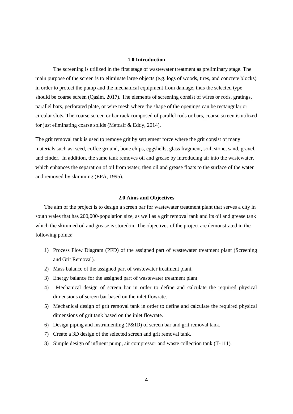
1.0 Introduction
The screening is utilized in the first stage of wastewater treatment as preliminary stage. The
main purpose of the screen is to eliminate large objects (e.g. logs of woods, tires, and concrete blocks)
in order to protect the pump and the mechanical equipment from damage, thus the selected type
should be coarse screen (Qasim, 2017). The elements of screening consist of wires or rods, gratings,
parallel bars, perforated plate, or wire mesh where the shape of the openings can be rectangular or
circular slots. The coarse screen or bar rack composed of parallel rods or bars, coarse screen is utilized
for just eliminating coarse solids (Metcalf & Eddy, 2014).
The grit removal tank is used to remove grit by settlement force where the grit consist of many
materials such as: seed, coffee ground, bone chips, eggshells, glass fragment, soil, stone, sand, gravel,
and cinder. In addition, the same tank removes oil and grease by introducing air into the wastewater,
which enhances the separation of oil from water, then oil and grease floats to the surface of the water
and removed by skimming (EPA, 1995).
2.0 Aims and Objectives
The aim of the project is to design a screen bar for wastewater treatment plant that serves a city in
south wales that has 200,000-population size, as well as a grit removal tank and its oil and grease tank
which the skimmed oil and grease is stored in. The objectives of the project are demonstrated in the
following points:
1) Process Flow Diagram (PFD) of the assigned part of wastewater treatment plant (Screening
and Grit Removal).
2) Mass balance of the assigned part of wastewater treatment plant.
3) Energy balance for the assigned part of wastewater treatment plant.
4) Mechanical design of screen bar in order to define and calculate the required physical
dimensions of screen bar based on the inlet flowrate.
5) Mechanical design of grit removal tank in order to define and calculate the required physical
dimensions of grit tank based on the inlet flowrate.
6) Design piping and instrumenting (P&ID) of screen bar and grit removal tank.
7) Create a 3D design of the selected screen and grit removal tank.
8) Simple design of influent pump, air compressor and waste collection tank (T-111).
4
Paraphrase This Document
Need a fresh take? Get an instant paraphrase of this document with our AI Paraphraser
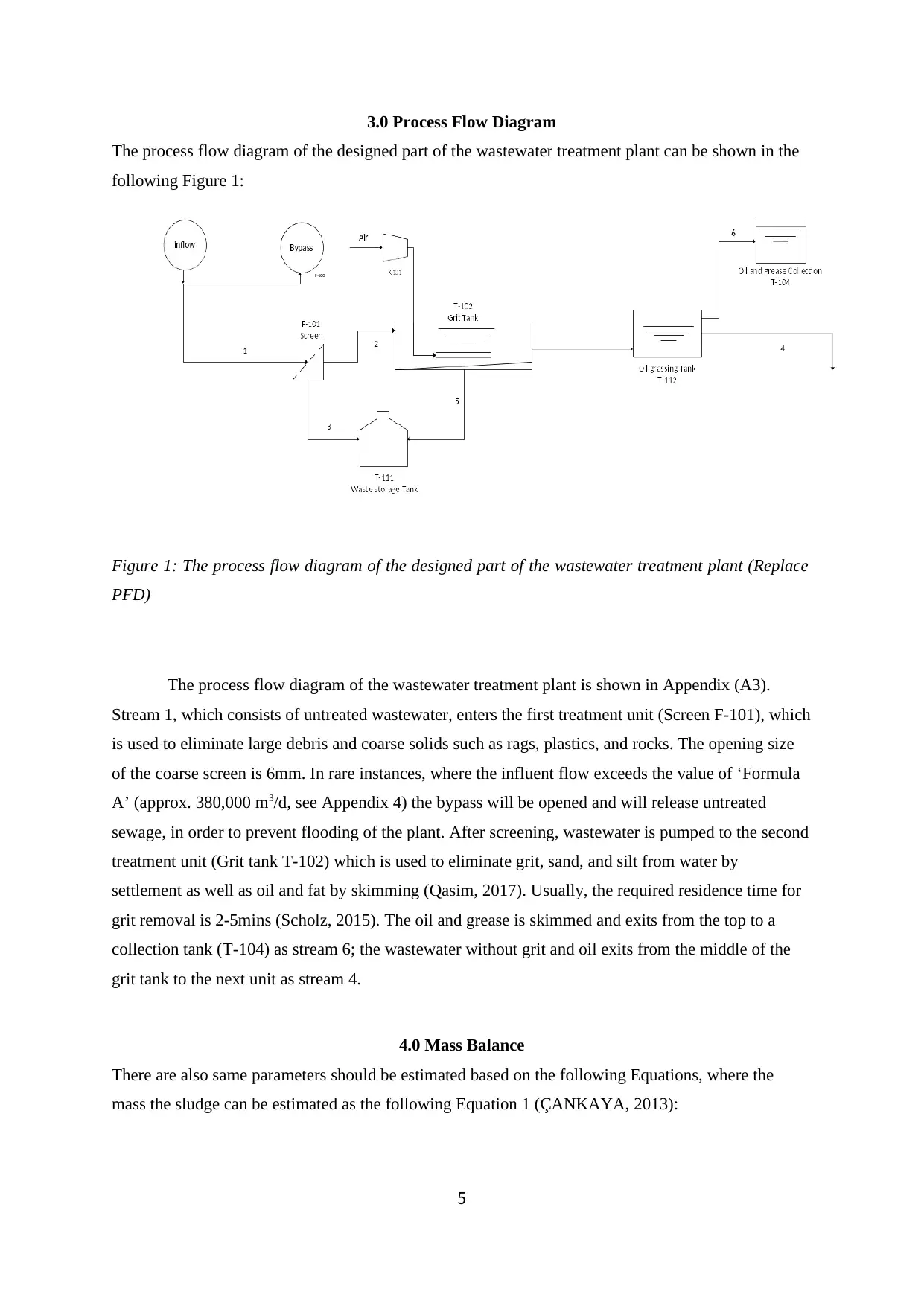
3.0 Process Flow Diagram
The process flow diagram of the designed part of the wastewater treatment plant can be shown in the
following Figure 1:
Figure 1: The process flow diagram of the designed part of the wastewater treatment plant (Replace
PFD)
The process flow diagram of the wastewater treatment plant is shown in Appendix (A3).
Stream 1, which consists of untreated wastewater, enters the first treatment unit (Screen F-101), which
is used to eliminate large debris and coarse solids such as rags, plastics, and rocks. The opening size
of the coarse screen is 6mm. In rare instances, where the influent flow exceeds the value of ‘Formula
A’ (approx. 380,000 m3/d, see Appendix 4) the bypass will be opened and will release untreated
sewage, in order to prevent flooding of the plant. After screening, wastewater is pumped to the second
treatment unit (Grit tank T-102) which is used to eliminate grit, sand, and silt from water by
settlement as well as oil and fat by skimming (Qasim, 2017). Usually, the required residence time for
grit removal is 2-5mins (Scholz, 2015). The oil and grease is skimmed and exits from the top to a
collection tank (T-104) as stream 6; the wastewater without grit and oil exits from the middle of the
grit tank to the next unit as stream 4.
4.0 Mass Balance
There are also same parameters should be estimated based on the following Equations, where the
mass the sludge can be estimated as the following Equation 1 (ÇANKAYA, 2013):
5
Mass of sludge=TSS∗Q
100 (1)
Where: (TSS : total suspended solid in mg/L (PPM), and Q : the volumetric flowrate of inlet
wastewater). The mass of volatile suspended solid can be estimated based on the following Equation 2
(ÇANKAYA, 2013):
Mass of VSS= VSS∗Q
100 (2)
Where: ( VSS : volatile suspended solid in mg/L (PPM), and Q : the volumetric flowrate of inlet
wastewater). The mass of BOD (biochemical oxygen demand) which refers to the required amount of
oxygen that would be consumed if all the organic materials, so it is an indicator for the amount of
organic matters in water. It is can be estimated based on the following Equation 3 (ÇANKAYA,
2013):
Mass of BOD= BOD∗Q
100 (3)
Where: (BOD : biochemical oxygen demand in mg/L (PPM), and Q : the volumetric flowrate of inlet
wastewater). The oil and grace can be estimated based on the following Equation 4:
Mass of OIL=oil conentration∗Q
100 (4)
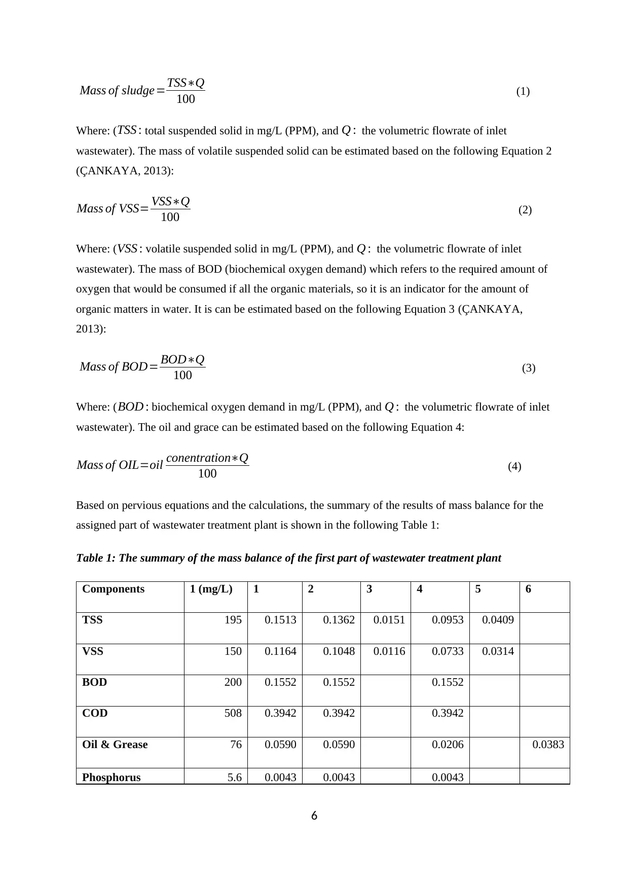
Based on pervious equations and the calculations, the summary of the results of mass balance for the
assigned part of wastewater treatment plant is shown in the following Table 1:
Table 1: The summary of the mass balance of the first part of wastewater treatment plant
Components 1 (mg/L) 1 2 3 4 5 6
TSS 195 0.1513 0.1362 0.0151 0.0953 0.0409
VSS 150 0.1164 0.1048 0.0116 0.0733 0.0314
BOD 200 0.1552 0.1552 0.1552
COD 508 0.3942 0.3942 0.3942
Oil & Grease 76 0.0590 0.0590 0.0206 0.0383
Phosphorus 5.6 0.0043 0.0043 0.0043
6
100 (1)
Where: (TSS : total suspended solid in mg/L (PPM), and Q : the volumetric flowrate of inlet
wastewater). The mass of volatile suspended solid can be estimated based on the following Equation 2
(ÇANKAYA, 2013):
Mass of VSS= VSS∗Q
100 (2)
Where: ( VSS : volatile suspended solid in mg/L (PPM), and Q : the volumetric flowrate of inlet
wastewater). The mass of BOD (biochemical oxygen demand) which refers to the required amount of
oxygen that would be consumed if all the organic materials, so it is an indicator for the amount of
organic matters in water. It is can be estimated based on the following Equation 3 (ÇANKAYA,
2013):
Mass of BOD= BOD∗Q
100 (3)
Where: (BOD : biochemical oxygen demand in mg/L (PPM), and Q : the volumetric flowrate of inlet
wastewater). The oil and grace can be estimated based on the following Equation 4:
Mass of OIL=oil conentration∗Q
100 (4)
Based on pervious equations and the calculations, the summary of the results of mass balance for the
assigned part of wastewater treatment plant is shown in the following Table 1:
Table 1: The summary of the mass balance of the first part of wastewater treatment plant
Components 1 (mg/L) 1 2 3 4 5 6
TSS 195 0.1513 0.1362 0.0151 0.0953 0.0409
VSS 150 0.1164 0.1048 0.0116 0.0733 0.0314
BOD 200 0.1552 0.1552 0.1552
COD 508 0.3942 0.3942 0.3942
Oil & Grease 76 0.0590 0.0590 0.0206 0.0383
Phosphorus 5.6 0.0043 0.0043 0.0043
6
⊘ This is a preview!⊘
Do you want full access?
Subscribe today to unlock all pages.
Trusted by 1+ million students worldwide
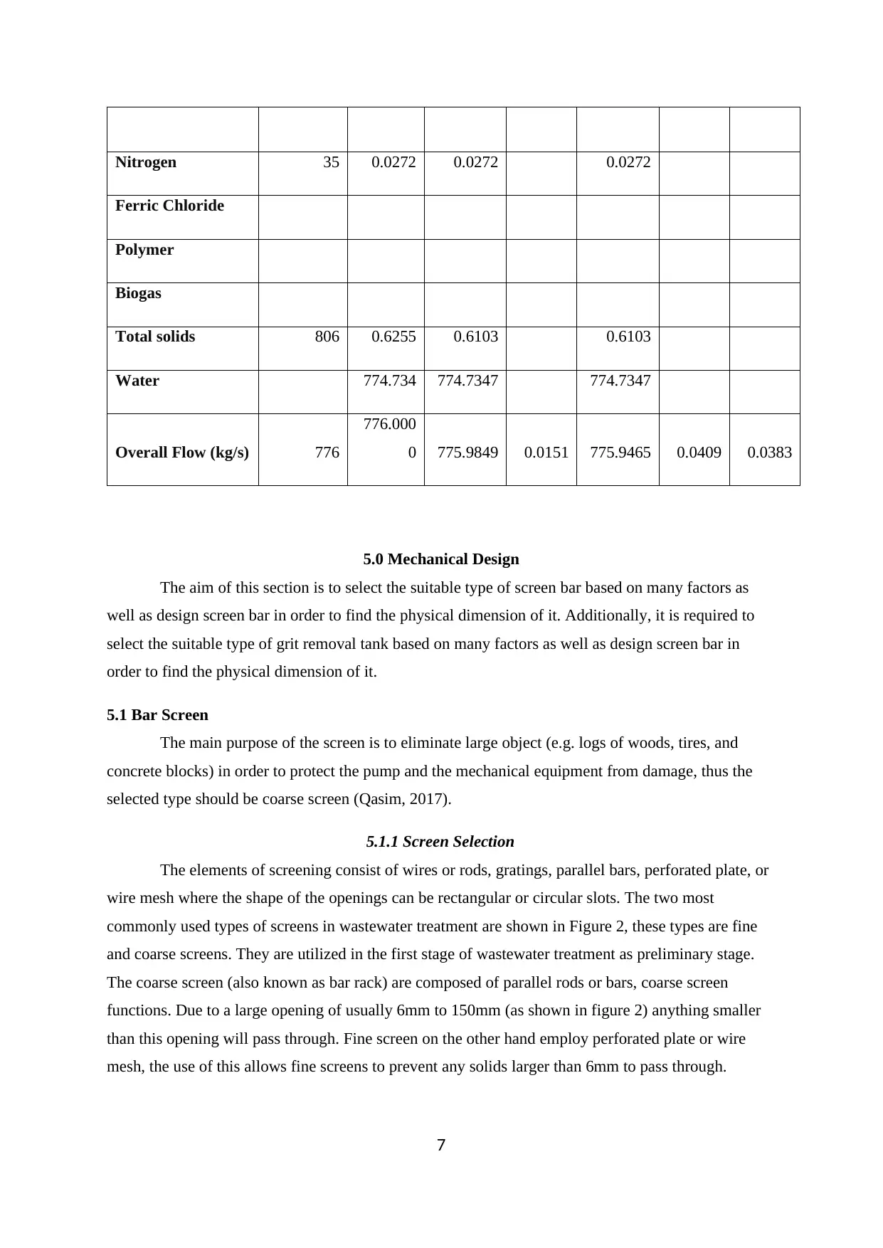
Nitrogen 35 0.0272 0.0272 0.0272
Ferric Chloride
Polymer
Biogas
Total solids 806 0.6255 0.6103 0.6103
Water 774.734 774.7347 774.7347
Overall Flow (kg/s) 776
776.000
0 775.9849 0.0151 775.9465 0.0409 0.0383
5.0 Mechanical Design
The aim of this section is to select the suitable type of screen bar based on many factors as
well as design screen bar in order to find the physical dimension of it. Additionally, it is required to
select the suitable type of grit removal tank based on many factors as well as design screen bar in
order to find the physical dimension of it.
5.1 Bar Screen
The main purpose of the screen is to eliminate large object (e.g. logs of woods, tires, and
concrete blocks) in order to protect the pump and the mechanical equipment from damage, thus the
selected type should be coarse screen (Qasim, 2017).
5.1.1 Screen Selection
The elements of screening consist of wires or rods, gratings, parallel bars, perforated plate, or
wire mesh where the shape of the openings can be rectangular or circular slots. The two most
commonly used types of screens in wastewater treatment are shown in Figure 2, these types are fine
and coarse screens. They are utilized in the first stage of wastewater treatment as preliminary stage.
The coarse screen (also known as bar rack) are composed of parallel rods or bars, coarse screen
functions. Due to a large opening of usually 6mm to 150mm (as shown in figure 2) anything smaller
than this opening will pass through. Fine screen on the other hand employ perforated plate or wire
mesh, the use of this allows fine screens to prevent any solids larger than 6mm to pass through.
7
Paraphrase This Document
Need a fresh take? Get an instant paraphrase of this document with our AI Paraphraser
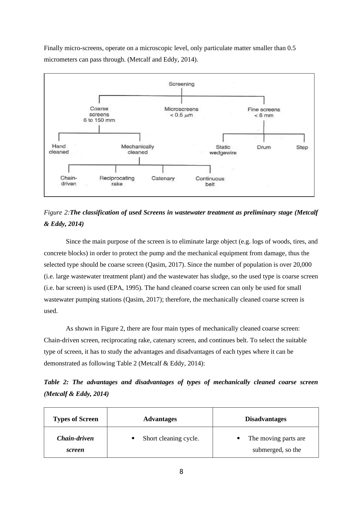
Finally micro-screens, operate on a microscopic level, only particulate matter smaller than 0.5
micrometers can pass through. (Metcalf and Eddy, 2014).
Figure 2:The classification of used Screens in wastewater treatment as preliminary stage (Metcalf
& Eddy, 2014)
Since the main purpose of the screen is to eliminate large object (e.g. logs of woods, tires, and
concrete blocks) in order to protect the pump and the mechanical equipment from damage, thus the
selected type should be coarse screen (Qasim, 2017). Since the number of population is over 20,000
(i.e. large wastewater treatment plant) and the wastewater has sludge, so the used type is coarse screen
(i.e. bar screen) is used (EPA, 1995). The hand cleaned coarse screen can only be used for small
wastewater pumping stations (Qasim, 2017); therefore, the mechanically cleaned coarse screen is
used.
As shown in Figure 2, there are four main types of mechanically cleaned coarse screen:
Chain-driven screen, reciprocating rake, catenary screen, and continues belt. To select the suitable
type of screen, it has to study the advantages and disadvantages of each types where it can be
demonstrated as following Table 2 (Metcalf & Eddy, 2014):
Table 2: The advantages and disadvantages of types of mechanically cleaned coarse screen
(Metcalf & Eddy, 2014)
Types of Screen Advantages Disadvantages
Chain-driven
screen
Short cleaning cycle. The moving parts are
submerged, so the
8
Utilized to application with
heavy duty.
maintenance requires for
shut down the process and
dewatering the channel.
Removal Efficiency is low.
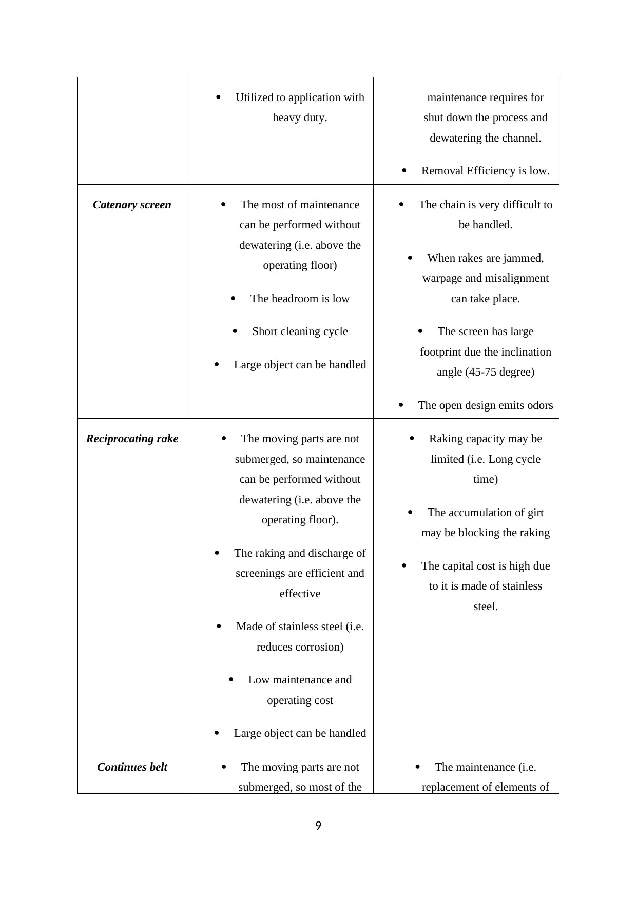
Catenary screen The most of maintenance
can be performed without
dewatering (i.e. above the
operating floor)
The headroom is low
Short cleaning cycle
Large object can be handled
The chain is very difficult to
be handled.
When rakes are jammed,
warpage and misalignment
can take place.
The screen has large
footprint due the inclination
angle (45-75 degree)
The open design emits odors
Reciprocating rake The moving parts are not
submerged, so maintenance
can be performed without
dewatering (i.e. above the
operating floor).
The raking and discharge of
screenings are efficient and
effective
Made of stainless steel (i.e.
reduces corrosion)
Low maintenance and
operating cost
Large object can be handled
Raking capacity may be
limited (i.e. Long cycle
time)
The accumulation of girt
may be blocking the raking
The capital cost is high due
to it is made of stainless
steel.
Continues belt The moving parts are not
submerged, so most of the
The maintenance (i.e.
replacement of elements of
9
heavy duty.
maintenance requires for
shut down the process and
dewatering the channel.
Removal Efficiency is low.
Catenary screen The most of maintenance
can be performed without
dewatering (i.e. above the
operating floor)
The headroom is low
Short cleaning cycle
Large object can be handled
The chain is very difficult to
be handled.
When rakes are jammed,
warpage and misalignment
can take place.
The screen has large
footprint due the inclination
angle (45-75 degree)
The open design emits odors
Reciprocating rake The moving parts are not
submerged, so maintenance
can be performed without
dewatering (i.e. above the
operating floor).
The raking and discharge of
screenings are efficient and
effective
Made of stainless steel (i.e.
reduces corrosion)
Low maintenance and
operating cost
Large object can be handled
Raking capacity may be
limited (i.e. Long cycle
time)
The accumulation of girt
may be blocking the raking
The capital cost is high due
to it is made of stainless
steel.
Continues belt The moving parts are not
submerged, so most of the
The maintenance (i.e.
replacement of elements of
9
⊘ This is a preview!⊘
Do you want full access?
Subscribe today to unlock all pages.
Trusted by 1+ million students worldwide
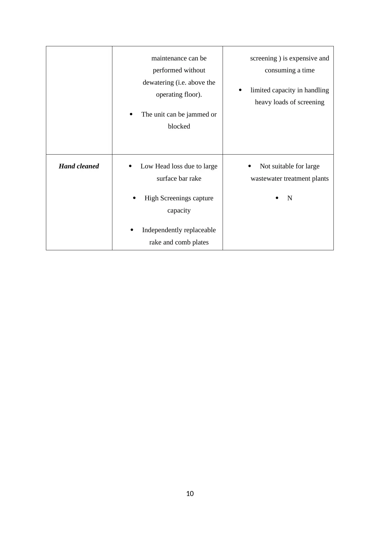
maintenance can be
performed without
dewatering (i.e. above the
operating floor).
The unit can be jammed or
blocked
screening ) is expensive and
consuming a time
limited capacity in handling
heavy loads of screening
Hand cleaned Low Head loss due to large
surface bar rake
High Screenings capture
capacity
Independently replaceable
rake and comb plates
Not suitable for large
wastewater treatment plants
N
10
Paraphrase This Document
Need a fresh take? Get an instant paraphrase of this document with our AI Paraphraser
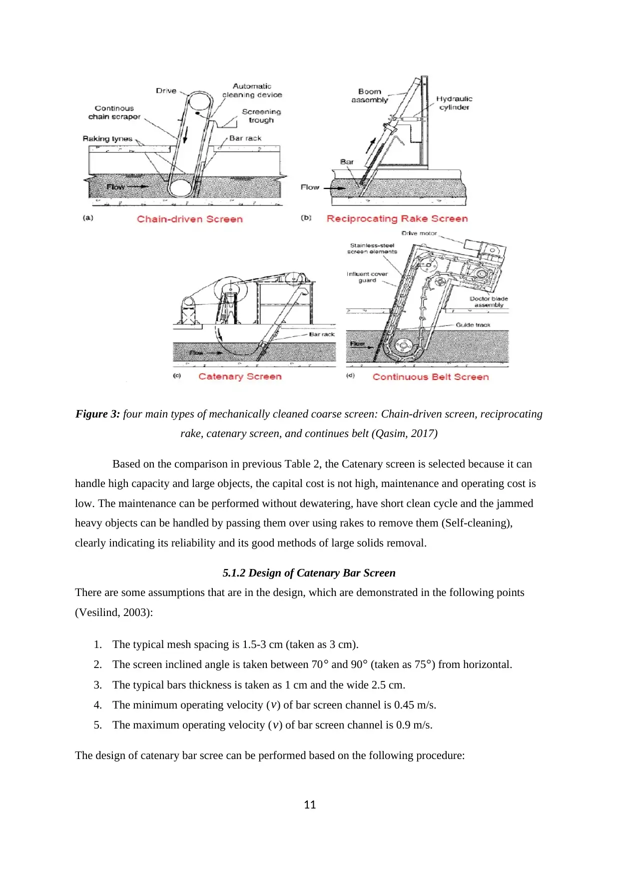
Figure 3: four main types of mechanically cleaned coarse screen: Chain-driven screen, reciprocating
rake, catenary screen, and continues belt (Qasim, 2017)
Based on the comparison in previous Table 2, the Catenary screen is selected because it can
handle high capacity and large objects, the capital cost is not high, maintenance and operating cost is
low. The maintenance can be performed without dewatering, have short clean cycle and the jammed
heavy objects can be handled by passing them over using rakes to remove them (Self-cleaning),
clearly indicating its reliability and its good methods of large solids removal.
5.1.2 Design of Catenary Bar Screen
There are some assumptions that are in the design, which are demonstrated in the following points
(Vesilind, 2003):
1. The typical mesh spacing is 1.5-3 cm (taken as 3 cm).
2. The screen inclined angle is taken between 70 ° and 90° (taken as 75°) from horizontal.
3. The typical bars thickness is taken as 1 cm and the wide 2.5 cm.
4. The minimum operating velocity ( v) of bar screen channel is 0.45 m/s.
5. The maximum operating velocity ( v) of bar screen channel is 0.9 m/s.
The design of catenary bar scree can be performed based on the following procedure:
11
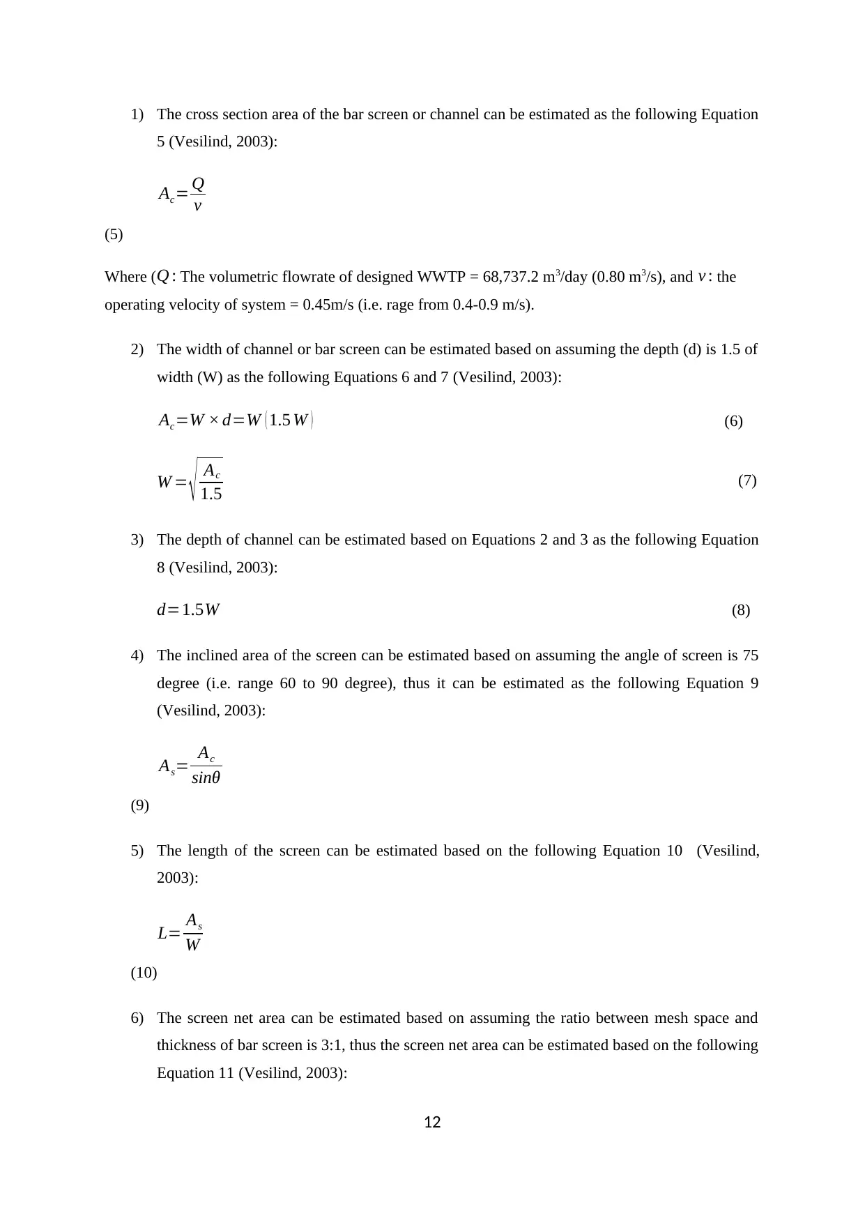
1) The cross section area of the bar screen or channel can be estimated as the following Equation
5 (Vesilind, 2003):
Ac= Q
v
(5)
Where ( Q : The volumetric flowrate of designed WWTP = 68,737.2 m3/day (0.80 m3/s), and v : the
operating velocity of system = 0.45m/s (i.e. rage from 0.4-0.9 m/s).
2) The width of channel or bar screen can be estimated based on assuming the depth (d) is 1.5 of
width (W) as the following Equations 6 and 7 (Vesilind, 2003):
Ac=W × d=W ( 1.5 W ) (6)
W = √ Ac
1.5 (7)
3) The depth of channel can be estimated based on Equations 2 and 3 as the following Equation
8 (Vesilind, 2003):
d=1.5W (8)
4) The inclined area of the screen can be estimated based on assuming the angle of screen is 75
degree (i.e. range 60 to 90 degree), thus it can be estimated as the following Equation 9
(Vesilind, 2003):
As= Ac
sinθ
(9)
5) The length of the screen can be estimated based on the following Equation 10 (Vesilind,
2003):
L= As
W
(10)
6) The screen net area can be estimated based on assuming the ratio between mesh space and
thickness of bar screen is 3:1, thus the screen net area can be estimated based on the following
Equation 11 (Vesilind, 2003):
12
⊘ This is a preview!⊘
Do you want full access?
Subscribe today to unlock all pages.
Trusted by 1+ million students worldwide
1 out of 64
Related Documents


Your All-in-One AI-Powered Toolkit for Academic Success.
+13062052269
info@desklib.com
Available 24*7 on WhatsApp / Email
![[object Object]](/_next/static/media/star-bottom.7253800d.svg)
Unlock your academic potential
Copyright © 2020–2026 A2Z Services. All Rights Reserved. Developed and managed by ZUCOL.