Wastewater Treatment Plant Design Project Report - Safety

Verified

Added on  2022/08/11

|7
|549
|19
Project
AI Summary
This project presents a comprehensive design of a wastewater treatment plant, focusing on the design of a bar screen, grit and grease removal tanks, and an aeration tank. The design considers a plant serving over 200,000 people in the UK. The project includes a detailed risk assessment of plant operations, identifying potential hazards associated with mechanical movements and electrical equipment. A What-If analysis is conducted to evaluate potential operational issues and recommend safeguards. Furthermore, the design of a feed air compressor is detailed, including specifications and performance calculations. The report also includes the design of influent main pump and piping and instrumenting. This project provides a practical application of environmental engineering principles to ensure efficient and safe wastewater treatment processes.
Document Page
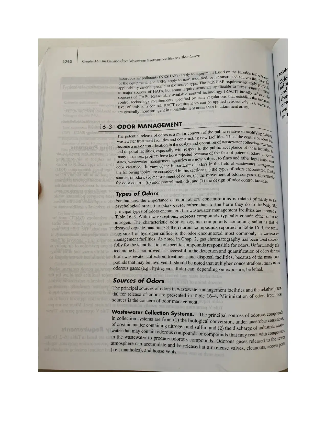
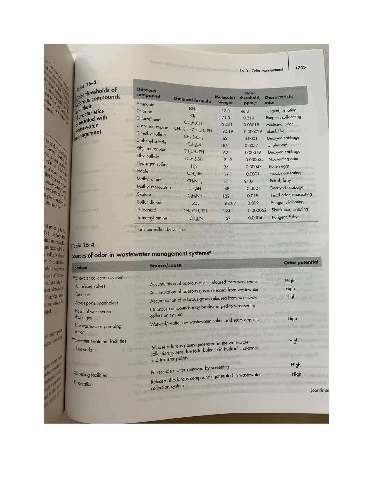
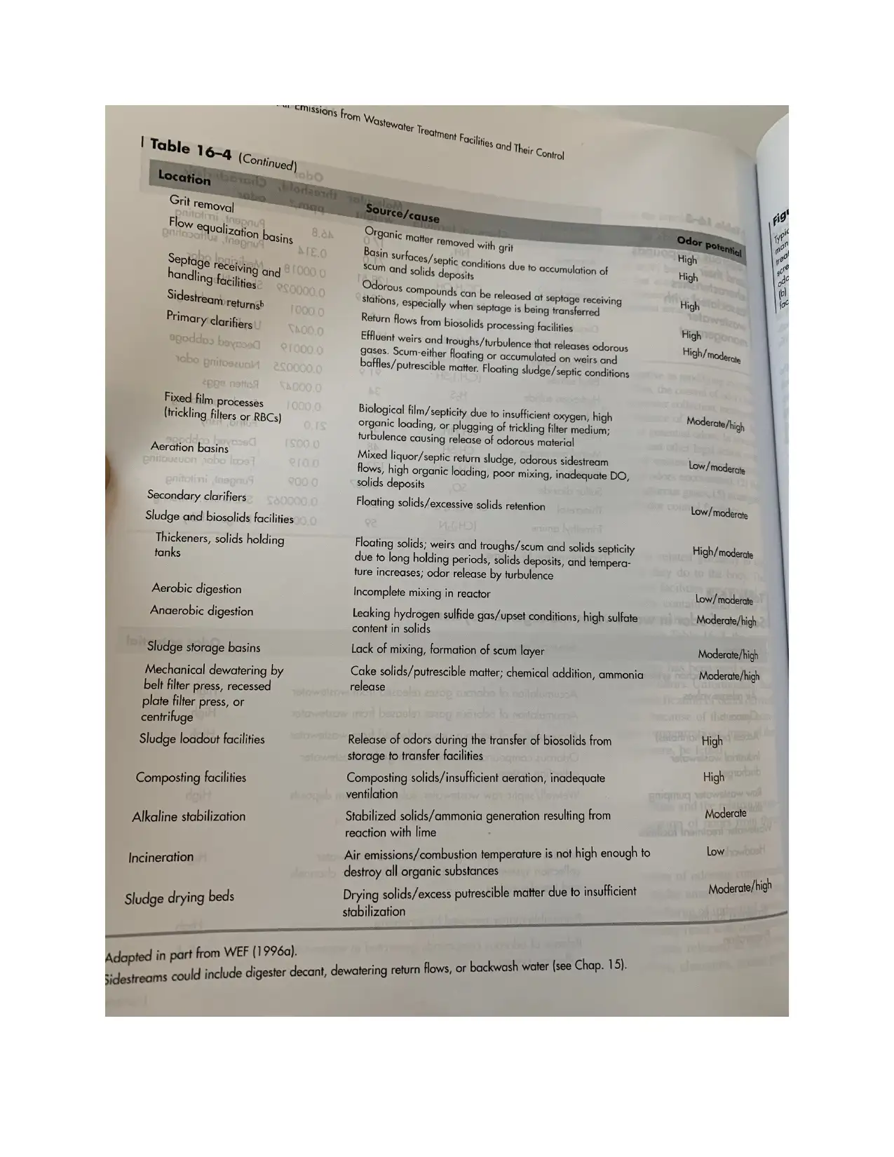
SAFETY CONSIDERATION DURING OPERATION
1.0 Risk assessment
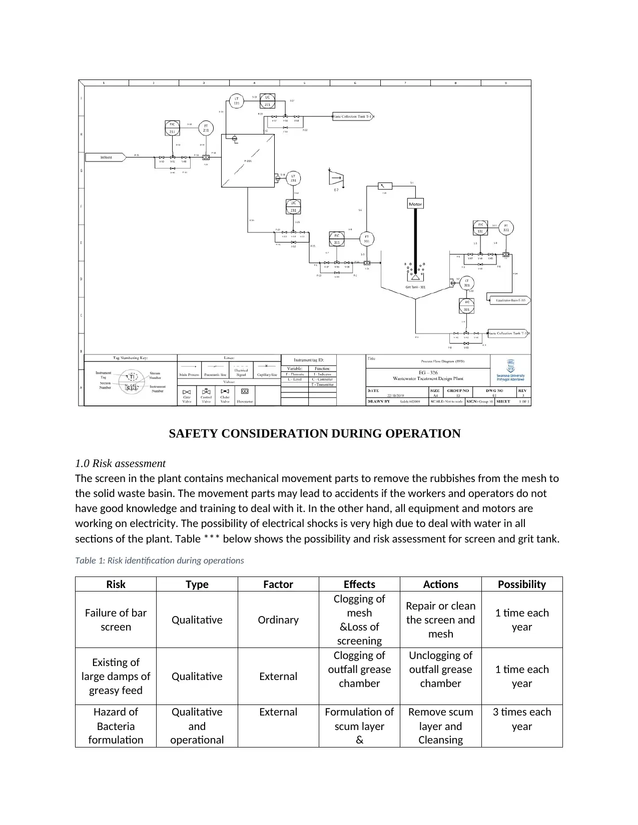
The screen in the plant contains mechanical movement parts to remove the rubbishes from the mesh to
the solid waste basin. The movement parts may lead to accidents if the workers and operators do not
have good knowledge and training to deal with it. In the other hand, all equipment and motors are
working on electricity. The possibility of electrical shocks is very high due to deal with water in all
sections of the plant. Table *** below shows the possibility and risk assessment for screen and grit tank.
Table 1: Risk identification during operations
Risk Type Factor Effects Actions Possibility
Failure of bar
screen Qualitative Ordinary
Clogging of
mesh
&Loss of
screening
Repair or clean
the screen and
mesh
1 time each
year
Existing of
large damps of
greasy feed
Qualitative External
Clogging of
outfall grease
chamber
Unclogging of
outfall grease
chamber
1 time each
year
Hazard of
Bacteria
formulation
Qualitative
and
operational
External Formulation of
scum layer
&
Remove scum
layer and
Cleansing
3 times each
year
tabler-icon-diamond-filled.svg

Paraphrase This Document

Need a fresh take? Get an instant paraphrase of this document with our AI Paraphraser
Document Page
Infection
Electrical
power outage
Operational Internal - No power
- electrical
shocks
Using
emergency
power supply
1 time each
year
2.0 What-IF analysis
Table below shows the What-IF analysis of Automatic Bar Screen and greasing removal tanks
Unit Screen Bar (E-101) Analysis Saleh
What-if Hazard Safeguard Recommendations
High flow of Feed?
Increase the level in the
tank and cumulative of
solid waste on the mesh
Cleaning the screen faster
than normal
Bypassing
Slowdown the feed
flow
Open drain
Open outfall valve
High solid waste in the
feed?
cumulative of solid waste
on the mesh
Cleaning the screen faster
than normal
Failure of feed control
valve?
Over flow + Biohazard
contamination
Maintenance team call
Manual calculation by globe
valve
Isolation and cleansing the
contaminated area
Flow Alarm install
Isolation of the failed
valve
Unit Aeration V-102 Analysis Saleh
What-if Hazard Safeguard Recommendations
High flow of feed?
Failure of aeration in tanks
& yield
Increase the level in the
tanks
Opening effluent valve
Recycling to feed storage
basin
Isolation of control
valve
Cleansing
Low level in the tank? Failure of aeration in tanks Emergency shutdown
Odor control? Psychological stress to
people
Mask
Ventilation
2.0 Feed air compressor design (Add this heading and info below under Ancillary
equipment)
The aim of the compressor is to compress and feed the air into the aeration tanks from the bottom. The
height of water in the tanks was found before to be 4m while the flowrate of air was found to be 1.08
m3/min. the required outlet pressure is found as:
Document Page
Pout=P¿+ρgh
Pout=101,325+ ( 1000 ) ( 9.81 ) ( 4 ) =105,245 Pa
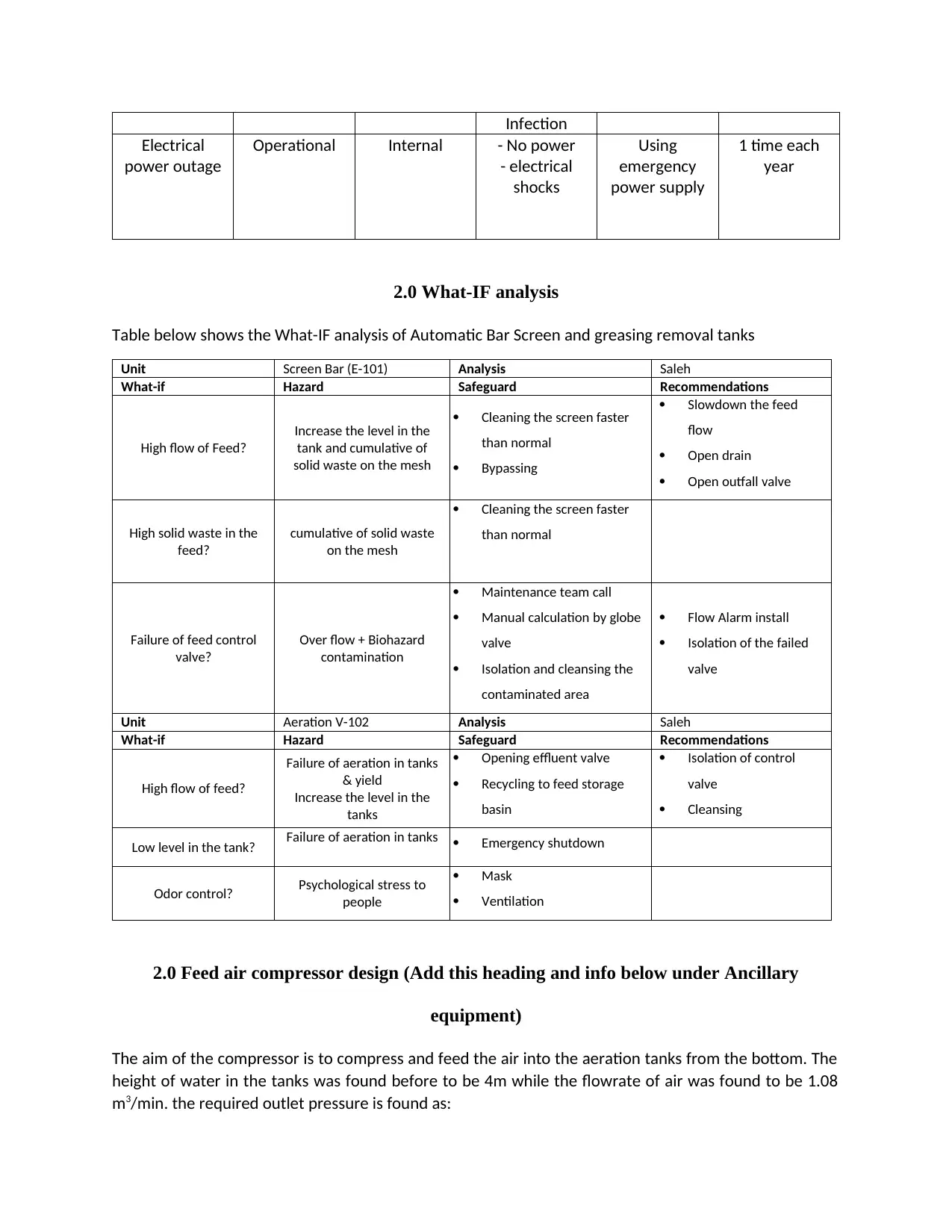
The design pressure will be taken as 25% additional where the design compressor pressure is 131.6 kPa.
The performance chart of selected compressor can be seen in Figure below:
- The pressure ratio is 131/101.3 = 1.3
- The mass flowrate= Mwt PV
RT
- The mass flowrate=29 ( 101.325 ) 1.08
8.314 (298) =1.28 kg /min (2.82lb /min) for each chamber
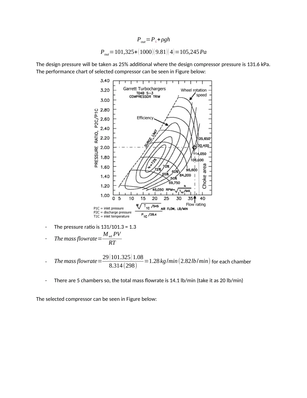
- There are 5 chambers so, the total mass flowrate is 14.1 lb/min (take it as 20 lb/min)
The selected compressor can be seen in Figure below:
Document Page
The specifications are:
1. Efficiency is 65%
2. Wheel rotation speed 55,000 rpm
3. Maximum flow 20 lb/min
4. Pressure ratio 1.3
5. Power is: Power=5 ( 1.08 ) ( 131101.3 )
0.65 =246.7 kJ
min =4.1123 kW
tabler-icon-diamond-filled.svg

Paraphrase This Document

Need a fresh take? Get an instant paraphrase of this document with our AI Paraphraser
Document Page
Document Page
Document Page
chevron_up_icon
1 out of 7
circle_padding
hide_on_mobile
zoom_out_icon
[object Object]