Water Level Indicator System Design Using NE555 Timer IC Project

Verified

Added on  2023/06/05

|7
|644
|350
Project
AI Summary
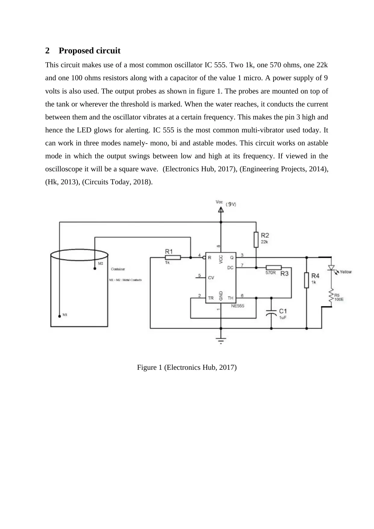
This project details the construction of a water level indicator using the NE555 timer IC, functioning as an astable multivibrator. The circuit utilizes resistors, a capacitor, and a 9V power supply to activate an LED when water reaches a designated level, completing the circuit between probes. The project addresses water wastage by providing a simple and cost-effective water alarm system. Challenges during development included ensuring proper connections, tuning the oscillator, managing LED intensity, and protecting the circuit from water damage. The project aims to expand in the next phase by incorporating multiple LEDs to indicate different water levels.
Document Page
Water Level Indicator using NE555
Timer
<Author name>
<Guide name>
<Month name yyyy>
Dissertation submitted in partial fulfillment for the degree
of
<Degree name> in <insert your degree title>
<Faculty name>
tabler-icon-diamond-filled.svg

Paraphrase This Document

Need a fresh take? Get an instant paraphrase of this document with our AI Paraphraser
Document Page
<University name>
Document Page
1 Introduction
1.1 Objectives
Water wastage is one of the main problem today and therefore it needs to be prevented using
water alarm. This circuit can be installed on the tanks and left to operate. When the water
reaches the top of the tank it glows a LED to alert that water needs to be controlled.
1.2 Significance
This circuit makes use of commonly found electronic components. This project can save
many dollars. Over watering is also a common issue that can be stopped using it. It makes use
of the basic principle of an astable multivibrator and for this IC 555 is used.
Document Page
2 Proposed circuit
This circuit makes use of a most common oscillator IC 555. Two 1k, one 570 ohms, one 22k
and one 100 ohms resistors along with a capacitor of the value 1 micro. A power supply of 9
volts is also used. The output probes as shown in figure 1. The probes are mounted on top of
the tank or wherever the threshold is marked. When the water reaches, it conducts the current
between them and the oscillator vibrates at a certain frequency. This makes the pin 3 high and
hence the LED glows for alerting. IC 555 is the most common multi-vibrator used today. It
can work in three modes namely- mono, bi and astable modes. This circuit works on astable
mode in which the output swings between low and high at its frequency. If viewed in the
oscilloscope it will be a square wave. (Electronics Hub, 2017), (Engineering Projects, 2014),
(Hk, 2013), (Circuits Today, 2018).
Figure 1 (Electronics Hub, 2017)
tabler-icon-diamond-filled.svg

Paraphrase This Document

Need a fresh take? Get an instant paraphrase of this document with our AI Paraphraser
Document Page
3 Progress to date
This project involved some challenges such as proper connections, tuning of the oscillator,
intensity of light emitted by the LED is proper, being a circuit and that to near a water source
was properly taken care of and it is protected from external damage. All the component are
working well. This circuit has to be made more portable and robust. This is a challenge of the
second phase. Better water-proofing is another aspect. If there is any loose or neglected
connection it will make the circuit useless as the current will not flow. This is another issue
that has to be taken care of.
Document Page
4 Conclusion
The simple and basic working of an astable multivibrator has been applied in this project. It is
made to vibrate at a frequency depending on the value of resistance and capacitance used.
When the water touches the probes it completes the circuit and it glows the LED. In the next
phase, different levels of water will be notified using different LEDs.
Document Page
5 References
Circuits Today. (2018, January 23). Water level alarm circuit. Retrieved from
http://www.circuitstoday.com: http://www.circuitstoday.com/water-level-alarm-
circuit
Electronics Hub. (2017, March 14). Water Level Alarm Using 555 Timer. Retrieved from
https://www.electronicshub.org: https://www.electronicshub.org/water-level-alarm-
using-555-timer/
Engineering Projects. (2014, September 19). Water Level Controller Using NE555. Retrieved
from https://bestengineeringprojects.com: https://bestengineeringprojects.com/water-
level-controller-using-ne555/
Hk, V. (2013, October 14). Water level controller using IC-555. Retrieved from
https://prezi.com: https://prezi.com/zitjaz8g60np/water-level-controller-using-ic-555/
chevron_up_icon
1 out of 7
circle_padding
hide_on_mobile
zoom_out_icon
[object Object]