Career Episode 1: Intelligent Overhead Tank Water Level Indicator

Verified

Added on  2020/03/04

|9
|1626
|474
Report
AI Summary
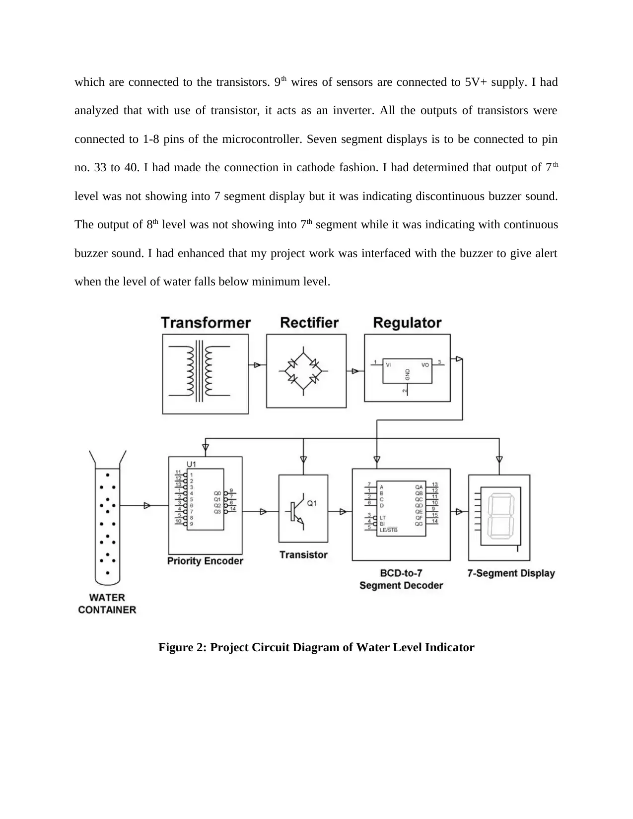
This report details a student's project on an intelligent overhead tank water level indicator, designed to display the water level with a scale of 0 to 9 using a 7-segment display. The project involved designing a low-cost water level indicator using a microcontroller, aiming to prevent water wastage. The system utilized a priority encoder, BCD-to-7 segment decoder, and 7-segment displays, with conductive sensors indicating water levels. The report covers the project's objectives, the student's role, technical details including circuit design, engineering knowledge applied, accomplishments, technical difficulties and solutions, and strategies for creative design. The student designed, developed, and tested the water level indicator, which automatically switched the pump on and off based on water levels and incorporated a buzzer alert. The report also includes collaborative work with team members and a summary of the project's outcome and the student's contributions.
Document Page
Competency Demonstration Report
Career Episode 1
tabler-icon-diamond-filled.svg

Secure Best Marks with AI Grader

Need help grading? Try our AI Grader for instant feedback on your assignments.
Document Page
a) Introduction
CE 1.1
Name of the project: Intelligent Overhead Tank Water Level Indicator
Location of the project: Khamman
Project Duration: December 2006 to May 2007
Name of the Organization: SRR Engineering College
Role and Designation during the time: Team Member
b) Project Background
CE 1.2 Nature of the overall engineering project
I had designed the project work on an intelligent overhead water level indicator to
provide a display of water level within the tank. I had provided the reading with a scale of 0 to 9.
While conducting this study, a priority encoder is being interfaced to the decoder to provide a
display of the water level on segment display of 7. I had designed the proposed system by use of
priority encoder, BCD-to-7 segment decoder and 7 segment displays. Due to higher input
impedance, a priority encoder senses water within the container from 9 input terminals. Level 9
indicates that the tank is full while level 1 indicates that tank is empty. I had taken the decision to
design water level indication as it will indicate level of water within the tank. It is used for
conducting of non corrosive as well as non-inflammable liquids.
Document Page
CE 1.3 Objectives of the project
Following are the objectives of this project work:
To design a low cost water level indicator
To use of microcontroller as a platform for designing the proposed system
To design the system in such a way that the components are able to prevent wastage of
water
CE 1.4 Nature of particular work area
I had designed a water level indicator circuit to build and install it round the home water
tank level for maintaining it automatically. I had mainly worked into the electronics field with
use of microcontroller. The microcontroller for the water level indicator had passed required tests
with other components were interfaced to it. With the proposed system, I was able to monitor the
water level into overhead tank, switch on the pump when the water tank is empty and vice versa.
I had done it to eliminate the wastage of water and cut off the water supply. In this project work,
microcontroller is required as the control signals are passed and developed by use of it. I had
interfaced LCD to the microcontroller to display status of operating system. Most of the water
level indicators were equipped to point out and perceive of single level.
Document Page
Head of the department of Electronics
Engineering
Course Tutor
Electronics engineering
student (Myself)
Electronics Engineer
Technicians
CE 1.5 Organizational structure chart
Figure 1: People involved in the project
CE 1.6 Statement of my duties
I had involved into design of water level indicator, develop and testing of components
and system that was used to design the proposed automatic system. I had involved into stage of
project such as initial brief of project concept, design and develop stage, test of prototypes and
final implementation of new system. I had worked with the cross functional project team
members for successfully working into this project.
c) Personal Workplace Activity
CE 1.7 Technical details of the work
I had given a constant of 5V power supply to microcontroller and remaining circuit from
the battery. The inputs were connected with +5V. Even the power supply consisted of step down
transformer of 230/12V. I had kept the ground terminal of sensor at bottom of the tank. For
designing the water tank, I had used of 9 conductive types of sensors and 8 wires of sensors
tabler-icon-diamond-filled.svg

Secure Best Marks with AI Grader

Need help grading? Try our AI Grader for instant feedback on your assignments.
Document Page
which are connected to the transistors. 9th wires of sensors are connected to 5V+ supply. I had
analyzed that with use of transistor, it acts as an inverter. All the outputs of transistors were
connected to 1-8 pins of the microcontroller. Seven segment displays is to be connected to pin
no. 33 to 40. I had made the connection in cathode fashion. I had determined that output of 7th
level was not showing into 7 segment display but it was indicating discontinuous buzzer sound.
The output of 8th level was not showing into 7th segment while it was indicating with continuous
buzzer sound. I had enhanced that my project work was interfaced with the buzzer to give alert
when the level of water falls below minimum level.
Figure 2: Project Circuit Diagram of Water Level Indicator
Document Page
CE 1.8 Engineering knowledge and skills applied in the project
I have associated with handing of electronics equipments and microcontroller based
devices. I have concerned with supervision and maintenance of the system, measured the
instruments and collected data from different instruments for process control and purpose of
automation. I have used of microcontroller for automating process of the water pumping into
overhead tank storage system. I have ability to detect the water level into the tank, switch
ON/OFF the pump and display the status of the system into LCD screen. Through this study, I
have provided a development into existing water level controller by using calibrated circuit to
point out the water level.
CE 1.9 Accomplishment and task performed
While working, I had considered three key significant conditions: there is no water into
source tank, intermediate level is either 3 to 7 and there is sufficient amount of water into source
tank. I had provided a brief of the three conditions as follows:
Condition 1: There is no water into source tank
I had analyzed that when the water tank is empty, there is no such conductive path among
8 indicating probes and probe that is connected to +5V power supply. It causes the sensor region
to have adequate biasing voltage. I had determined that it resulted into cut off the region and
output transversely the collector had 4.2V. I had used of microcontroller into active low region
while provided transistor output of 4.2V, that was considered as low by use of microcontroller. I
had analyzed that default value is 0 by use of microcontroller to 7 segment display as it indicated
that tank is empty.
Document Page
Condition 2: Intermediate levels
The water started to fill the tank which was established among sensing probes and also
common probe. The transistor output is now (1.2-1.8V). I had used of microcontroller to
program for detecting high priority input and displayed equivalent level of water into 7 segment
display. In this particular project work, I had analyzed that when level of water reached 7th level,
then a discontinuous buzzer was activated across one level beside with display of 7th segment. It
was warning that the tank is going to be filled soon.
Condition 3: Water full
When the tank was full, the top level of the probe got conductive path throughout water
and the transistor got into conduction. The output provided to the microcontroller was not only
showing into 7th segment while it was indicating with continuous buzzer sound. Therefore, I had
understood that the tank is full and switched off the motor and saved the water.
CE 1.10 Technical difficulties and solutions
While implementing the proposed system, I had faced problems such as lot of ICs were
damaged to solder them on Vero board and I had used of sockets to protect the legs. Open
circuits are also constituted issue as some of the soldered wires were not making correct contact
with Vero board.
I had conducted a root cause analysis of the printed circuit board to overcome with the
issues. The damaged IC is repaired by rehearing and permitting it to cool uninterrupted. The
joints of IC are repaired by reheating of the joint with use of hot iron until there is flowing of
solder.
tabler-icon-diamond-filled.svg

Paraphrase This Document

Need a fresh take? Get an instant paraphrase of this document with our AI Paraphraser
Document Page
CE 1.11 Strategies to include original and creative design work
The project work is creative and innovative as it is based on design of water level
indicator using 8 transistors that are conducted as level rises. Buzzer was added to start as the
level of water becomes full, and auto buzzer started with microcontroller. This project showed
water level with help of 7 segment display and also buzzer.
CE 1.12 Collaborative work with other team members
I had written project specifications and technical project report. I had improved the
detailed design on use of electronic equipments and microcontroller. Finally, I had carried out
the project planning stage and prepared the timeline. I had worked with the project members and
submitted the final project report on scheduled time.
d) Summary
CE 1.13 Overview of the project
Automatic water level controller will start the pump set as the level of water falls down
below predetermined level. It was switched off the pump set when the water tank was full. The
work was enhanced by interfacing with buzzer to alert when the level falls below minimum.
CE 1.14 Project work fared to meet goals
I have used of microcontroller for automating process of the water pumping into
overhead tank storage system.
Document Page
CE 1.15 Personal role contributed to the project
I had worried with administration and safeguarding of the system, calculated the
instruments and composed of project related data from dissimilar instruments for process control
and purpose of automation.
chevron_up_icon
1 out of 9
circle_padding
hide_on_mobile
zoom_out_icon
logo.png

Your All-in-One AI-Powered Toolkit for Academic Success.

Available 24*7 on WhatsApp / Email

[object Object]