La Trobe University: Weather Balloon Design and Analysis Report
VerifiedAdded on 2023/02/01
|9
|1758
|61
Report
AI Summary
This report provides a comprehensive overview of high-altitude weather balloon design, focusing on the principles and calculations involved in creating these systems for atmospheric research and climate monitoring. It delves into the various subsystems, including balloon and navigation, communication, on-board data handling and payload, and structure and thermal systems. The report examines the challenges of traditional ballooning, such as temperature and humidity measurement contamination, and presents detailed design principles, including payload calculations and the use of the ideal gas law to determine balloon volume and gas requirements. Furthermore, it explores advanced technologies, such as the double balloon technique, to reduce payload and ensure controlled descent. The report concludes with a discussion of the advantages and disadvantages of different methods, emphasizing the importance of reducing measurement contamination and ensuring the accuracy of data collected during ascents and descents. The report is enriched with figures, graphs, and tables to illustrate key concepts and data analysis.
1.0 Introduction:
High altitude weather balloons are unmanned and filled with helium or hydrogen gas
for the floating. This can go upto an altitude of 50-80 km. The weather balloons are
used for climate and meteorological research. This paper involves the study of
design calculation and process of lifting of the weather balloon. The weather balloon
system can be divided into 5 sub division namely Balloon and navigation,
Communication, on-board data handling and payload, structure and thermal system.
For the designing of weather balloon initially the aim of the mission is determined
accordingly the parameters are calculated. Before implementing the subsystem in
the main assembly all the components are individually tested and the final assembly
is also tested for high temperature, low pressure and high vibration due to rise in the
altitude.
2.0 Traditional Ballooning Problem:
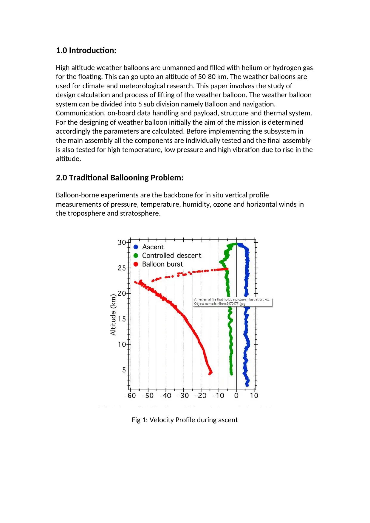
Balloon-borne experiments are the backbone for in situ vertical profile
measurements of pressure, temperature, humidity, ozone and horizontal winds in
the troposphere and stratosphere.
Fig 1: Velocity Profile during ascent
Paraphrase This Document
Need a fresh take? Get an instant paraphrase of this document with our AI Paraphraser
2.1 Temperature Measurement Contamination:
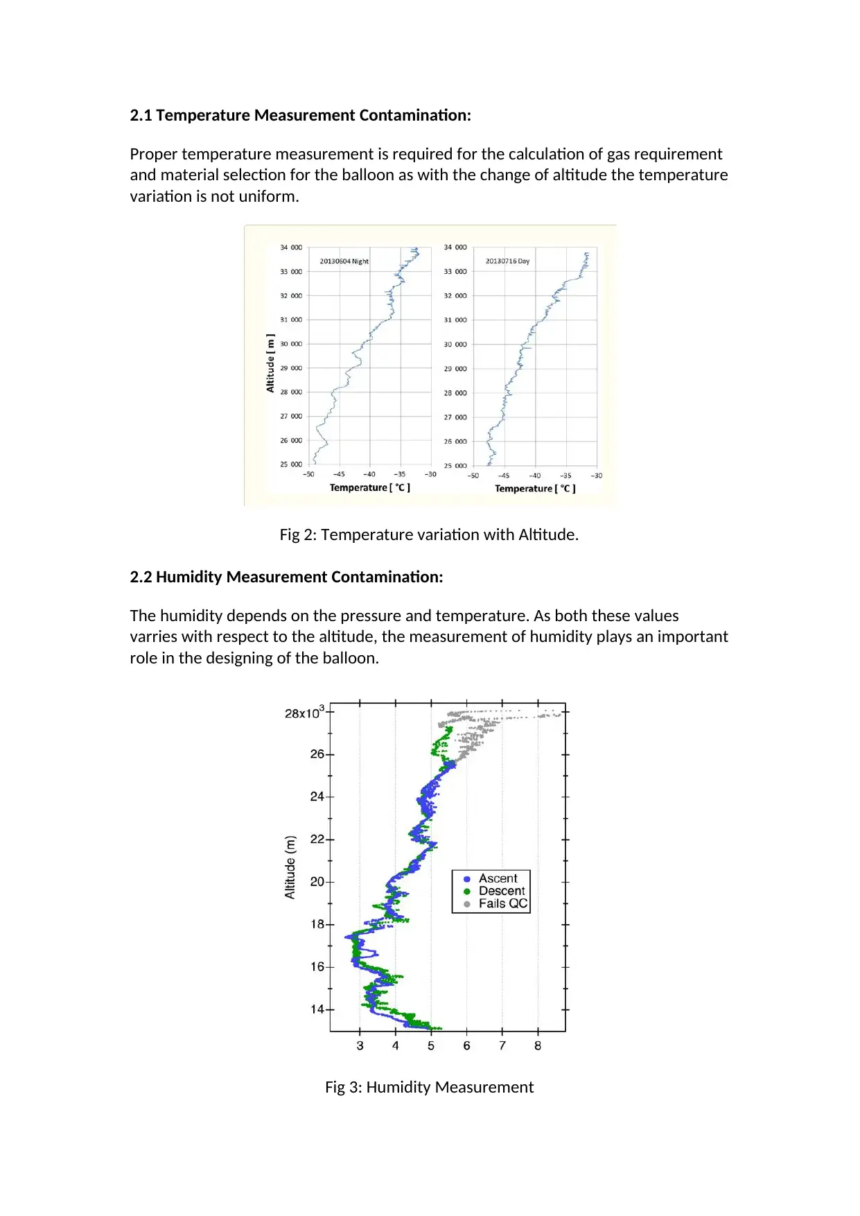
Proper temperature measurement is required for the calculation of gas requirement
and material selection for the balloon as with the change of altitude the temperature
variation is not uniform.
Fig 2: Temperature variation with Altitude.
2.2 Humidity Measurement Contamination:
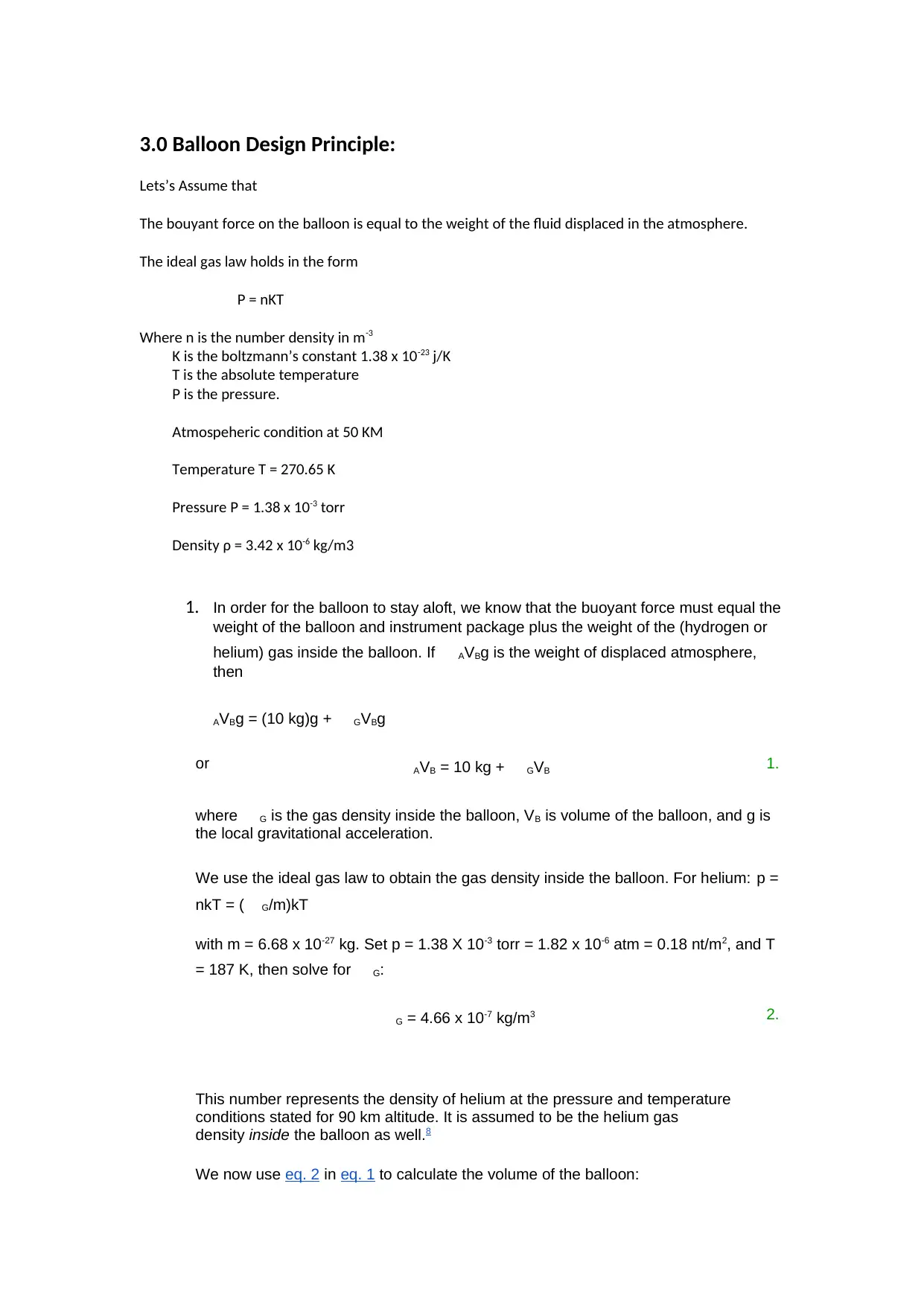
The humidity depends on the pressure and temperature. As both these values
varries with respect to the altitude, the measurement of humidity plays an important
role in the designing of the balloon.
Fig 3: Humidity Measurement
3.0 Balloon Design Principle:
Lets’s Assume that
The bouyant force on the balloon is equal to the weight of the fluid displaced in the atmosphere.
The ideal gas law holds in the form
P = nKT
Where n is the number density in m-3
K is the boltzmann’s constant 1.38 x 10⁻²³ j/K
T is the absolute temperature
P is the pressure.
Atmospeheric condition at 50 KM
Temperature T = 270.65 K
Pressure P = 1.38 x 10⁻³ torr
Density ρ = 3.42 x 10⁻⁶ kg/m3
1. In order for the balloon to stay aloft, we know that the buoyant force must equal the
weight of the balloon and instrument package plus the weight of the (hydrogen or
helium) gas inside the balloon. If AVBg is the weight of displaced atmosphere,
then
AVBg = (10 kg)g + GVBg
or AVB = 10 kg + GVB 1.
where G is the gas density inside the balloon, VB is volume of the balloon, and g is
the local gravitational acceleration.
We use the ideal gas law to obtain the gas density inside the balloon. For helium: p =
nkT = ( G/m)kT
with m = 6.68 x 10⁻²⁷ kg. Set p = 1.38 X 10⁻³ torr = 1.82 x 10⁻⁶ atm = 0.18 nt/m2, and T
= 187 K, then solve for G:
G = 4.66 x 10⁻⁷ kg/m3 2.
This number represents the density of helium at the pressure and temperature
conditions stated for 90 km altitude. It is assumed to be the helium gas
density inside the balloon as well.8
We now use eq. 2 in eq. 1 to calculate the volume of the balloon:
⊘ This is a preview!⊘
Do you want full access?
Subscribe today to unlock all pages.

Trusted by 1+ million students worldwide
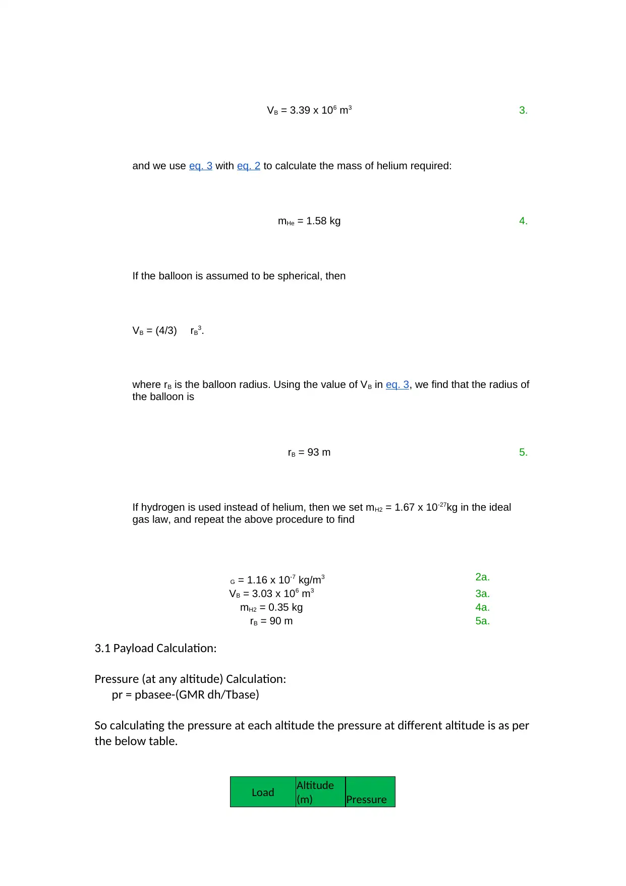
VB = 3.39 x 10⁶ m3 3.
and we use eq. 3 with eq. 2 to calculate the mass of helium required:
mHe = 1.58 kg 4.
If the balloon is assumed to be spherical, then
VB = (4/3) rB3.
where rB is the balloon radius. Using the value of VB in eq. 3, we find that the radius of
the balloon is
rB = 93 m 5.
If hydrogen is used instead of helium, then we set mH2 = 1.67 x 10⁻²⁷kg in the ideal
gas law, and repeat the above procedure to find
G = 1.16 x 10⁻⁷ kg/m3 2a.
VB = 3.03 x 10⁶ m3 3a.
mH2 = 0.35 kg 4a.
rB = 90 m 5a.
3.1 Payload Calculation:
Pressure (at any altitude) Calculation:
pr = pbasee-(GMR dh/Tbase)
So calculating the pressure at each altitude the pressure at different altitude is as per
the below table.
Load Altitude
(m) Pressure
Paraphrase This Document
Need a fresh take? Get an instant paraphrase of this document with our AI Paraphraser
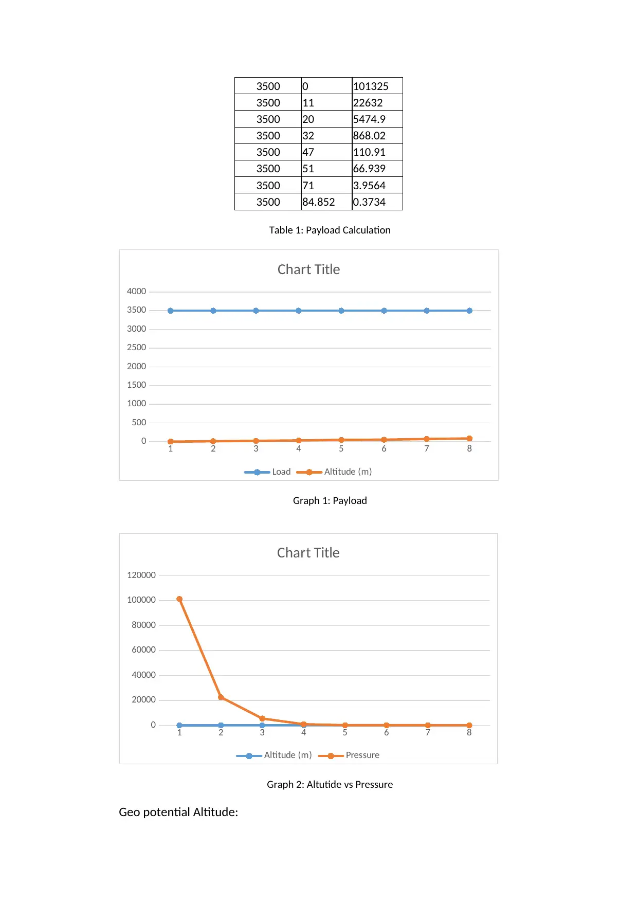
3500 0 101325
3500 11 22632
3500 20 5474.9
3500 32 868.02
3500 47 110.91
3500 51 66.939
3500 71 3.9564
3500 84.852 0.3734
Table 1: Payload Calculation
1 2 3 4 5 6 7 8
0
500
1000
1500
2000
2500
3000
3500
4000
Chart Title
Load Altitude (m)
Graph 1: Payload
1 2 3 4 5 6 7 8
0
20000
40000
60000
80000
100000
120000
Chart Title
Altitude (m) Pressure
Graph 2: Altutide vs Pressure
Geo potential Altitude:
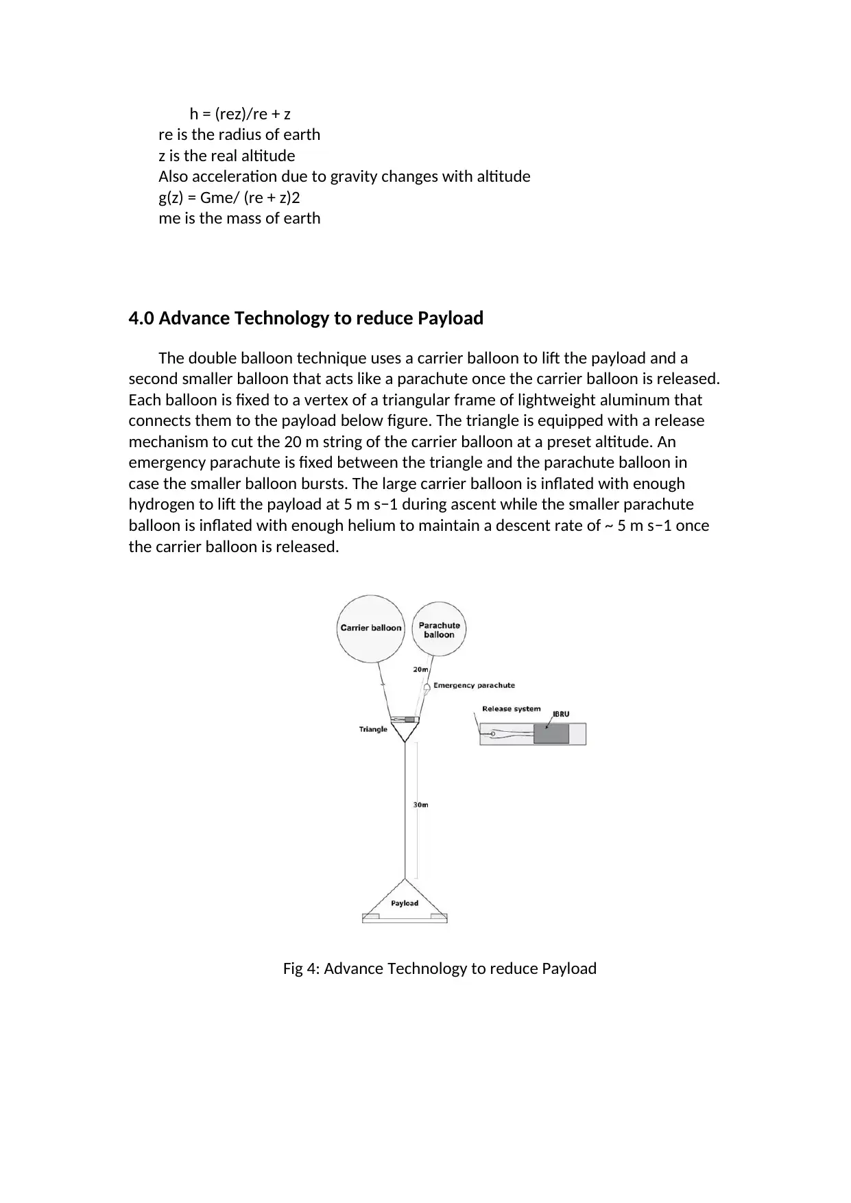
h = (rez)/re + z
re is the radius of earth
z is the real altitude
Also acceleration due to gravity changes with altitude
g(z) = Gme/ (re + z)2
me is the mass of earth
4.0 Advance Technology to reduce Payload
The double balloon technique uses a carrier balloon to lift the payload and a
second smaller balloon that acts like a parachute once the carrier balloon is released.
Each balloon is fixed to a vertex of a triangular frame of lightweight aluminum that
connects them to the payload below figure. The triangle is equipped with a release
mechanism to cut the 20 m string of the carrier balloon at a preset altitude. An
emergency parachute is fixed between the triangle and the parachute balloon in
case the smaller balloon bursts. The large carrier balloon is inflated with enough
hydrogen to lift the payload at 5 m s−1 during ascent while the smaller parachute
balloon is inflated with enough helium to maintain a descent rate of ~ 5 m s−1 once
the carrier balloon is released.
Fig 4: Advance Technology to reduce Payload
⊘ This is a preview!⊘
Do you want full access?
Subscribe today to unlock all pages.

Trusted by 1+ million students worldwide
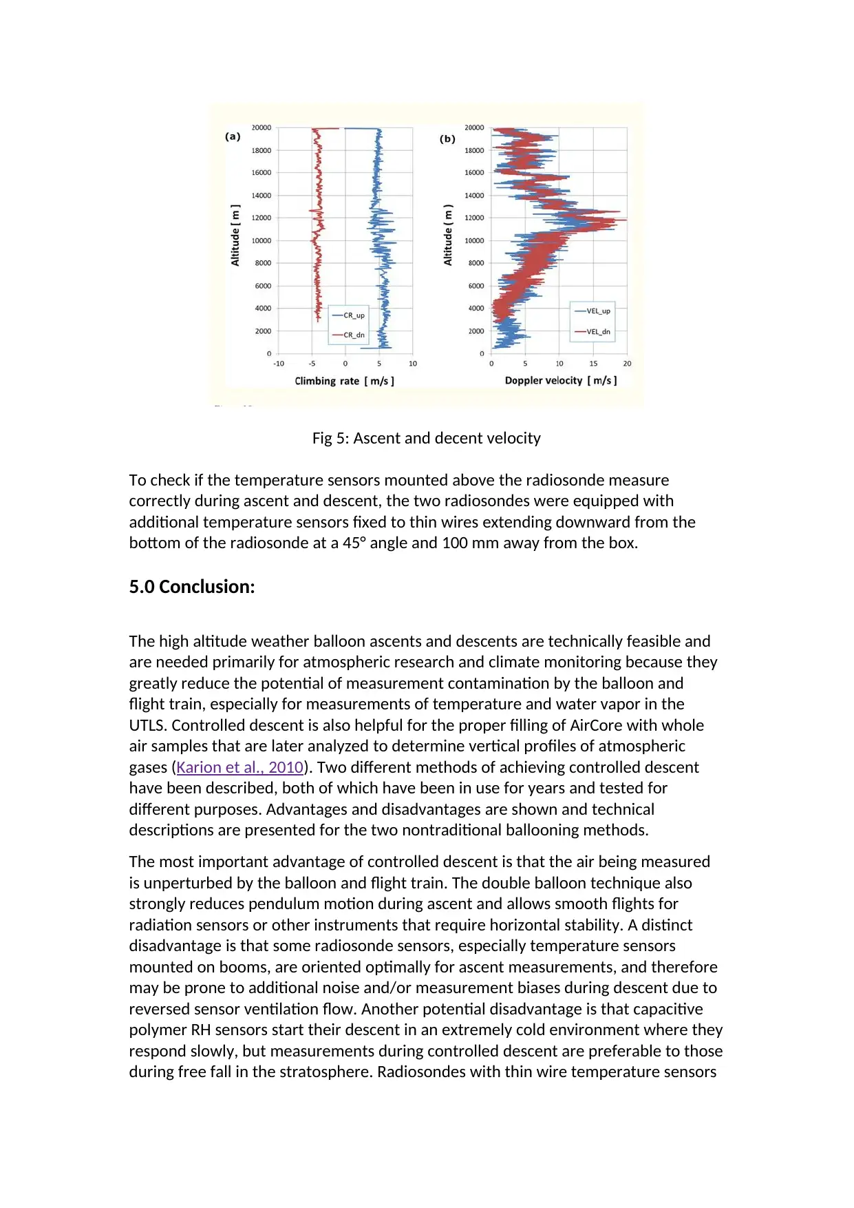
Fig 5: Ascent and decent velocity
To check if the temperature sensors mounted above the radiosonde measure
correctly during ascent and descent, the two radiosondes were equipped with
additional temperature sensors fixed to thin wires extending downward from the
bottom of the radiosonde at a 45° angle and 100 mm away from the box.
5.0 Conclusion:
The high altitude weather balloon ascents and descents are technically feasible and
are needed primarily for atmospheric research and climate monitoring because they
greatly reduce the potential of measurement contamination by the balloon and
flight train, especially for measurements of temperature and water vapor in the
UTLS. Controlled descent is also helpful for the proper filling of AirCore with whole
air samples that are later analyzed to determine vertical profiles of atmospheric
gases (Karion et al., 2010). Two different methods of achieving controlled descent
have been described, both of which have been in use for years and tested for
different purposes. Advantages and disadvantages are shown and technical
descriptions are presented for the two nontraditional ballooning methods.
The most important advantage of controlled descent is that the air being measured
is unperturbed by the balloon and flight train. The double balloon technique also
strongly reduces pendulum motion during ascent and allows smooth flights for
radiation sensors or other instruments that require horizontal stability. A distinct
disadvantage is that some radiosonde sensors, especially temperature sensors
mounted on booms, are oriented optimally for ascent measurements, and therefore
may be prone to additional noise and/or measurement biases during descent due to
reversed sensor ventilation flow. Another potential disadvantage is that capacitive
polymer RH sensors start their descent in an extremely cold environment where they
respond slowly, but measurements during controlled descent are preferable to those
during free fall in the stratosphere. Radiosondes with thin wire temperature sensors
Paraphrase This Document
Need a fresh take? Get an instant paraphrase of this document with our AI Paraphraser

not mounted on sensor booms are much less sensitive to the direction of ventilation
flow and are well-suited for measurements during balloon descent.
flow and are well-suited for measurements during balloon descent.
Reference:
Bodeker GE, Bojinski S, Cimini D, Dirksen RJ, Haeffelin M, Hannigan JW, Hurst
DF, Leblanc T, Madonna F, Maturilli M, Mikalsen AC, Philipona R, Reale T,
Seidel DJ, Tan DGH, Thorne PW, Vömel H, Wang J., “Upper-Air Observations
for Climate: From Concept to Reality.” B Am Meteorol Soc. July 2016;97, PP
123–135.
Forster PMF, Shine KP., “Assessing the climate impact of trends in
stratospheric water vapour.” Geophys Res Lett. Aug 2002; pp 29-1086
GCOS-112. GCOS , “Upper-Air Network (GRUAN): Justification, requirements,
siting and instrumentation options. (WMO TD No. 1379)”.Technical
Document
112. 2007:25.https://www.wmo.int/pages/prog/gcos/Publications/gcos-
112.pdf.
Hurst DH, Oltmans SJ, Vömel H, Rosenlof KH, Davis SM, Ray EA, Hall EG,
Jordan AF. Stratospheric water vapor trends over Boulder, Colorado: Analysis
of the 30 year Boulder record. J Geophys Res. 2011;116:D02306. doi:
10.1029/2010JD015065.
Karion A, Sweeney C, Tans P, Newberger T. AirCore: An Innovative
Atmospheric Sampling System. J Atmos Ocean Tech. 2010;27:1839–1853. doi:
10.1175/2010JTECHA1448.1.
Lykov A, Khaykin S, Yushkov V, Korshunov L, Cocquerez P. “Observations of
water vapour on board long-duration super pressure balloon using flash-B
Lyman-alpha hygrometer. Conference Paper, Proceedings of the 19th ESA
Symposium on European Rocket and Balloon Programmes and Related
Research”; June 2009; pp 159-164
Mastenbrook HJ. “A control system for ascent-descent soundings of the
atmosphere. J Appl Meteorol”. May 1966;pp-737–740.
Nash J, Oakley T, Vömel H, Li W. “World Meteorological Organization
Instruments and Observing Methods. Yangjiang, China: 2011. WMO
Intercomparison of high quality radiosonde observing systems. Aug 2010, pp
164-177
⊘ This is a preview!⊘
Do you want full access?
Subscribe today to unlock all pages.

Trusted by 1+ million students worldwide
1 out of 9
Your All-in-One AI-Powered Toolkit for Academic Success.
+13062052269
info@desklib.com
Available 24*7 on WhatsApp / Email
![[object Object]](/_next/static/media/star-bottom.7253800d.svg)
Unlock your academic potential
Copyright © 2020–2025 A2Z Services. All Rights Reserved. Developed and managed by ZUCOL.
