Analysis of Wind Turbine Power Generation with Matlab Simulation
VerifiedAdded on 2023/02/01
|31
|14391
|64
Homework Assignment
AI Summary
This assignment provides a comprehensive analysis of wind turbine power generation, covering the fundamental principles of operation, including the conversion of wind's kinetic energy into electrical power. The solution details the essential components of a wind turbine, such as rotor blades, gearbox, generator, and nacelle, and explains how they work together to generate electricity. The assignment includes a detailed mathematical model of wind turbine power, deriving equations for kinetic energy, power density, and power extraction from the wind. It also discusses the significance of the power coefficient (Cp) and tip speed ratio (TSR) in wind turbine design and performance. Furthermore, the assignment explores the power flow within a wind turbine D.C generator, providing equations to determine the overall efficiency of the system. A Matlab code is included, allowing users to input wind speed and turbine blade radius to calculate power coefficient, tip speed ratio, angular velocity, and to plot the TSR against power efficiency for different resistances. The code is designed to simulate the behavior of a wind turbine under varying conditions. This analysis is helpful for electrical engineering students.

1
Student
Instructor
Matlab assignment
Date
Student
Instructor
Matlab assignment
Date
Paraphrase This Document
Need a fresh take? Get an instant paraphrase of this document with our AI Paraphraser
2
Introduction
Wind turbines are electricity generating plants which harness kinetic energy of the wind into electric
power. Operation principle basically depends on the wind as the prime mover, rotating turbine
blades that are coupled to the generation via gear chain. Essential parts of the turbine includes rotor
blades, brakes, controller, generator, gearbox, low and high speed shaft, nacelle and the pitch.
Rotor blades.
They are used to harness wind power by converting velocity of the wind into mechanical rotation of
the rotor shaft coupled.
Breaks.
Stops the rotor from rotating in case of emergencies.
Controller.
It is used to start up wind power system when the speed of the wind is within the perquisite range. It
also stops turbine system from operating when the wind speed is way up the standard limit.
Gearbox.
The gearbox is the interface between low speed shaft and high speed shaft. The low speed shaft is
connected to the rotor blades while the high speed shaft is connected to the rotor shaft of the
generator. Ultimate function of the gearbox is to multiple low speed of the low speed shaft from
about 20 to 60 RPM to high speed of about 1000 to 1800 RPM depending on the rated RPM of the
generator.
Generator.
The output of the generator depends on the type of the generator used and kind of power required.
In case of the AC electricity, the generator is usually an induction motor type that produces 60 cycle
frequency of the electricity. For the D.C system, DC generators are employed to convert rotational
power of the shaft into its equivalent and steady DC output electricity.
Nacelle.
It is the housing that sits atop the towers. It accommodates gear box system and generator system.
Pitch.
It controls the blades by turning them out for maximum tracking of the upstream wind [1].
How wind turbines generates electricity
The rotor blades that are usually located on the front of the turbine system have been specially
curved to shapes similar to airfoil wings of the plane. Moving wind hits up the blades causing a lift
force which rotates the blades’ low speed shaft. The kinetic energy dropped by the upstream wind is
therefore said to have been converted to the mechanical energy awaiting chain of transformation to
electrical energy. The amount of energy developed by the turbine blades is directly proportional to
the total cross sectional area of the blades that is swept through by the upstream wind.
3
The speed of low shaft is multiplied by the gain of the gearbox so as to be in sync with the RPM
rating of the generator. The rotor of the generator is connected to the gearbox at the high speed
end. Efficiency of the gearbox accounts for bearing and gear train frictional losses.
In the generator, rotational mechanical energy is transduced into electrical energy which is fed into
the supply system or utility network. Frictional and windage losses of the generator is also
accounted for by the general efficiency of the generator.
Equation of wind turbine.
Speed and power relations.
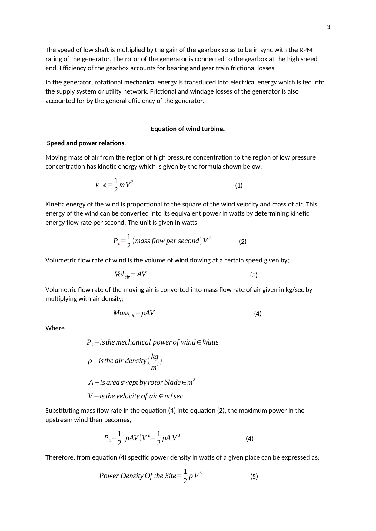
Moving mass of air from the region of high pressure concentration to the region of low pressure
concentration has kinetic energy which is given by the formula shown below;
k . e= 1
2 mV 2 (1)
Kinetic energy of the wind is proportional to the square of the wind velocity and mass of air. This
energy of the wind can be converted into its equivalent power in watts by determining kinetic
energy flow rate per second. The unit is given in watts.
P¿=1
2 (mass flow per second)V 2 (2)
Volumetric flow rate of wind is the volume of wind flowing at a certain speed given by;
Volair= AV (3)
Volumetric flow rate of the moving air is converted into mass flow rate of air given in kg/sec by
multiplying with air density;
Massair=ρAV (4)
Where
P¿−isthe mechanical power of wind ∈Watts
ρ−isthe air density ( kg
m3 )
A−is area swept by rotor blade∈m2
V −is the velocity of air∈m/ sec
Substituting mass flow rate in the equation (4) into equation (2), the maximum power in the
upstream wind then becomes,
P¿=1
2 ( ρAV ) V 2= 1
2 ρA V 3 (4)
Therefore, from equation (4) specific power density in watts of a given place can be expressed as;
Power Density Of the Site= 1
2 ρ V 3 (5)
The speed of low shaft is multiplied by the gain of the gearbox so as to be in sync with the RPM
rating of the generator. The rotor of the generator is connected to the gearbox at the high speed
end. Efficiency of the gearbox accounts for bearing and gear train frictional losses.
In the generator, rotational mechanical energy is transduced into electrical energy which is fed into
the supply system or utility network. Frictional and windage losses of the generator is also
accounted for by the general efficiency of the generator.
Equation of wind turbine.
Speed and power relations.
Moving mass of air from the region of high pressure concentration to the region of low pressure
concentration has kinetic energy which is given by the formula shown below;
k . e= 1
2 mV 2 (1)
Kinetic energy of the wind is proportional to the square of the wind velocity and mass of air. This
energy of the wind can be converted into its equivalent power in watts by determining kinetic
energy flow rate per second. The unit is given in watts.
P¿=1
2 (mass flow per second)V 2 (2)
Volumetric flow rate of wind is the volume of wind flowing at a certain speed given by;
Volair= AV (3)
Volumetric flow rate of the moving air is converted into mass flow rate of air given in kg/sec by
multiplying with air density;
Massair=ρAV (4)
Where
P¿−isthe mechanical power of wind ∈Watts
ρ−isthe air density ( kg
m3 )
A−is area swept by rotor blade∈m2
V −is the velocity of air∈m/ sec
Substituting mass flow rate in the equation (4) into equation (2), the maximum power in the
upstream wind then becomes,
P¿=1
2 ( ρAV ) V 2= 1
2 ρA V 3 (4)
Therefore, from equation (4) specific power density in watts of a given place can be expressed as;
Power Density Of the Site= 1
2 ρ V 3 (5)
⊘ This is a preview!⊘
Do you want full access?
Subscribe today to unlock all pages.
Trusted by 1+ million students worldwide
4
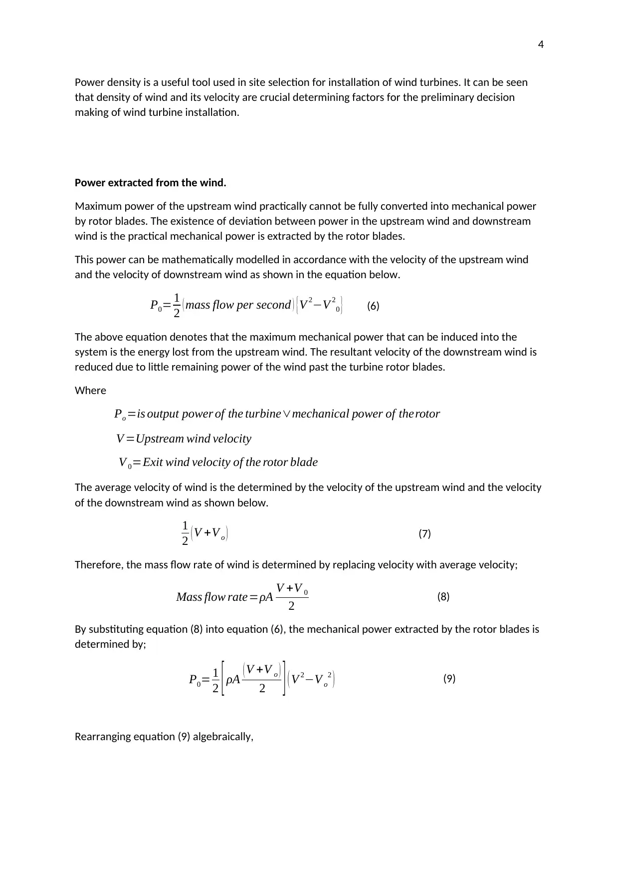
Power density is a useful tool used in site selection for installation of wind turbines. It can be seen
that density of wind and its velocity are crucial determining factors for the preliminary decision
making of wind turbine installation.
Power extracted from the wind.
Maximum power of the upstream wind practically cannot be fully converted into mechanical power
by rotor blades. The existence of deviation between power in the upstream wind and downstream
wind is the practical mechanical power is extracted by the rotor blades.
This power can be mathematically modelled in accordance with the velocity of the upstream wind
and the velocity of downstream wind as shown in the equation below.
P0= 1
2 ( mass flow per second ) {V 2−V 2
0 } (6)
The above equation denotes that the maximum mechanical power that can be induced into the
system is the energy lost from the upstream wind. The resultant velocity of the downstream wind is
reduced due to little remaining power of the wind past the turbine rotor blades.
Where
Po =is output power of the turbine∨mechanical power of therotor
V =Upstream wind velocity
V 0=Exit wind velocity of the rotor blade
The average velocity of wind is the determined by the velocity of the upstream wind and the velocity
of the downstream wind as shown below.
1
2 ( V +V o ) (7)
Therefore, the mass flow rate of wind is determined by replacing velocity with average velocity;
Mass flow rate=ρA V +V 0
2 (8)
By substituting equation (8) into equation (6), the mechanical power extracted by the rotor blades is
determined by;
P0= 1
2 [ ρA ( V +V o )
2 ] ( V 2−V o
2 ) (9)
Rearranging equation (9) algebraically,
Paraphrase This Document
Need a fresh take? Get an instant paraphrase of this document with our AI Paraphraser
5
Po =1
2 ρA V 3
(1+ V 0
V ) [1− ( V 0
V )2
]
2
(10)
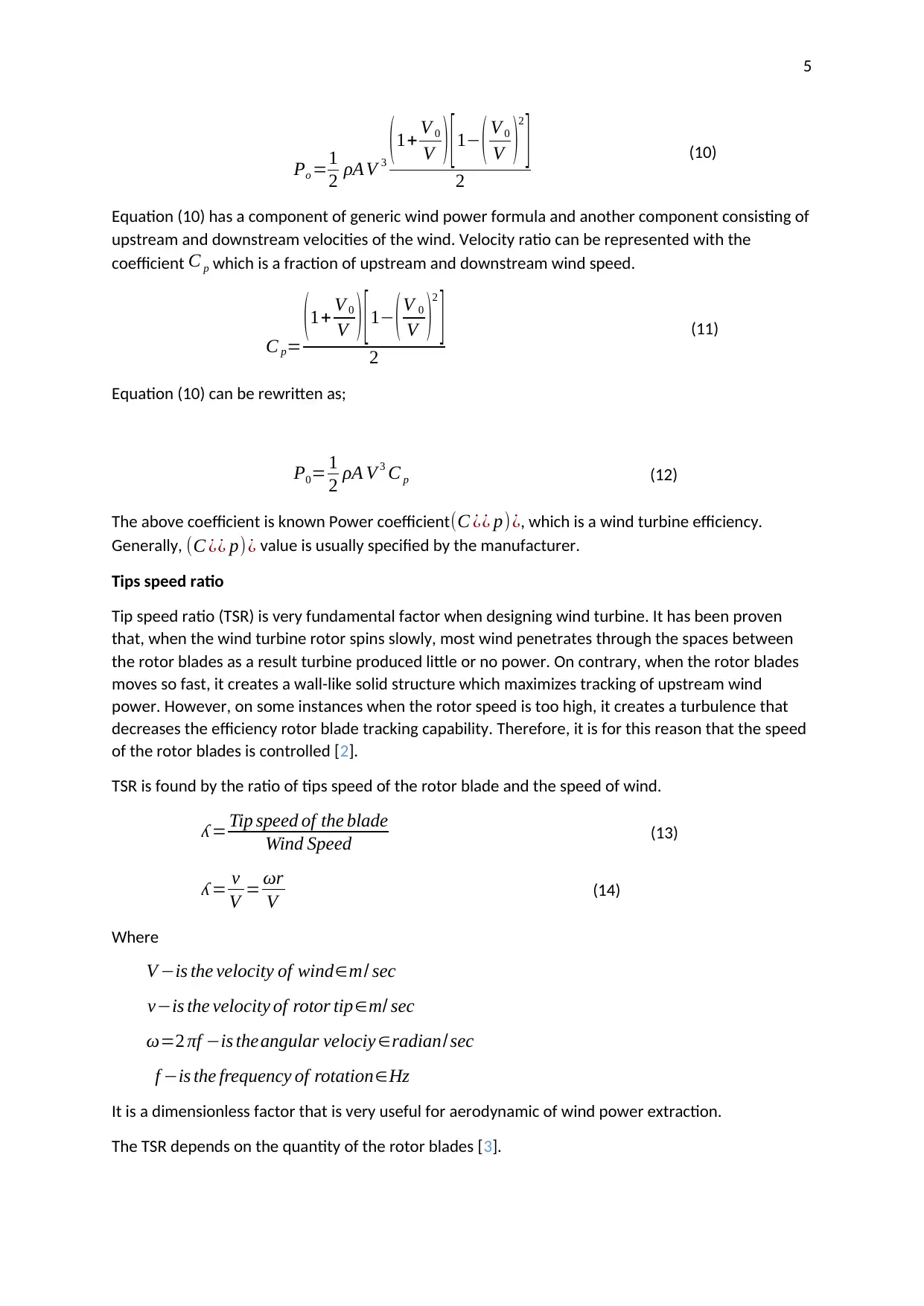
Equation (10) has a component of generic wind power formula and another component consisting of
upstream and downstream velocities of the wind. Velocity ratio can be represented with the
coefficient C p which is a fraction of upstream and downstream wind speed.
C p=
(1+ V 0
V ) [1− (V 0
V )2
]
2
(11)
Equation (10) can be rewritten as;
P0= 1
2 ρA V 3 C p (12)
The above coefficient is known Power coefficient (C ¿¿ p)¿, which is a wind turbine efficiency.
Generally, (C ¿¿ p)¿ value is usually specified by the manufacturer.
Tips speed ratio
Tip speed ratio (TSR) is very fundamental factor when designing wind turbine. It has been proven
that, when the wind turbine rotor spins slowly, most wind penetrates through the spaces between
the rotor blades as a result turbine produced little or no power. On contrary, when the rotor blades
moves so fast, it creates a wall-like solid structure which maximizes tracking of upstream wind
power. However, on some instances when the rotor speed is too high, it creates a turbulence that
decreases the efficiency rotor blade tracking capability. Therefore, it is for this reason that the speed
of the rotor blades is controlled [2].
TSR is found by the ratio of tips speed of the rotor blade and the speed of wind.
ʎ = Tip speed of the blade
Wind Speed (13)
ʎ = v
V = ωr
V (14)
Where
V −is the velocity of wind∈m/ sec
v−is the velocity of rotor tip∈m/ sec
ω=2 πf −is theangular velociy ∈radian/ sec
f −is the frequency of rotation∈Hz
It is a dimensionless factor that is very useful for aerodynamic of wind power extraction.
The TSR depends on the quantity of the rotor blades [3].
Po =1
2 ρA V 3
(1+ V 0
V ) [1− ( V 0
V )2
]
2
(10)
Equation (10) has a component of generic wind power formula and another component consisting of
upstream and downstream velocities of the wind. Velocity ratio can be represented with the
coefficient C p which is a fraction of upstream and downstream wind speed.
C p=
(1+ V 0
V ) [1− (V 0
V )2
]
2
(11)
Equation (10) can be rewritten as;
P0= 1
2 ρA V 3 C p (12)
The above coefficient is known Power coefficient (C ¿¿ p)¿, which is a wind turbine efficiency.
Generally, (C ¿¿ p)¿ value is usually specified by the manufacturer.
Tips speed ratio
Tip speed ratio (TSR) is very fundamental factor when designing wind turbine. It has been proven
that, when the wind turbine rotor spins slowly, most wind penetrates through the spaces between
the rotor blades as a result turbine produced little or no power. On contrary, when the rotor blades
moves so fast, it creates a wall-like solid structure which maximizes tracking of upstream wind
power. However, on some instances when the rotor speed is too high, it creates a turbulence that
decreases the efficiency rotor blade tracking capability. Therefore, it is for this reason that the speed
of the rotor blades is controlled [2].
TSR is found by the ratio of tips speed of the rotor blade and the speed of wind.
ʎ = Tip speed of the blade
Wind Speed (13)
ʎ = v
V = ωr
V (14)
Where
V −is the velocity of wind∈m/ sec
v−is the velocity of rotor tip∈m/ sec
ω=2 πf −is theangular velociy ∈radian/ sec
f −is the frequency of rotation∈Hz
It is a dimensionless factor that is very useful for aerodynamic of wind power extraction.
The TSR depends on the quantity of the rotor blades [3].
6
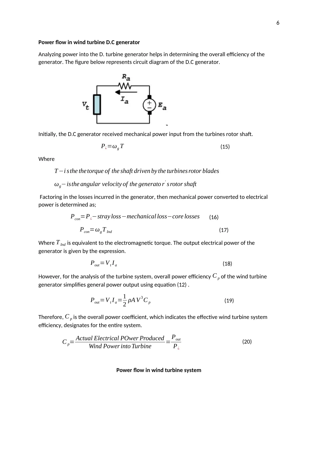
Power flow in wind turbine D.C generator
Analyzing power into the D. turbine generator helps in determining the overall efficiency of the
generator. The figure below represents circuit diagram of the D.C generator.
Initially, the D.C generator received mechanical power input from the turbines rotor shaft.
P¿=ωg T (15)
Where
T −i s the thetorque of the shaft driven by the turbines rotor blades
ωg−isthe angular velocity of the generato r' s rotor shaft
Factoring in the losses incurred in the generator, then mechanical power converted to electrical
power is determined as;
Pcon=P¿−stray loss−mechanical loss−core losses (16)
Pcon=ωg T Ind (17)
Where T Ind is equivalent to the electromagnetic torque. The output electrical power of the
generator is given by the expression.
Pout=V t I a (18)
However, for the analysis of the turbine system, overall power efficiency C p of the wind turbine
generator simplifies general power output using equation (12) .
Pout=V t I a =1
2 ρA V 3 C p (19)
Therefore, C p is the overall power coefficient, which indicates the effective wind turbine system
efficiency, designates for the entire system.
C p= Actual Electrical POwer Produced
Wind Power into Turbine = Pout
P¿
(20)
Power flow in wind turbine system
⊘ This is a preview!⊘
Do you want full access?
Subscribe today to unlock all pages.
Trusted by 1+ million students worldwide
7
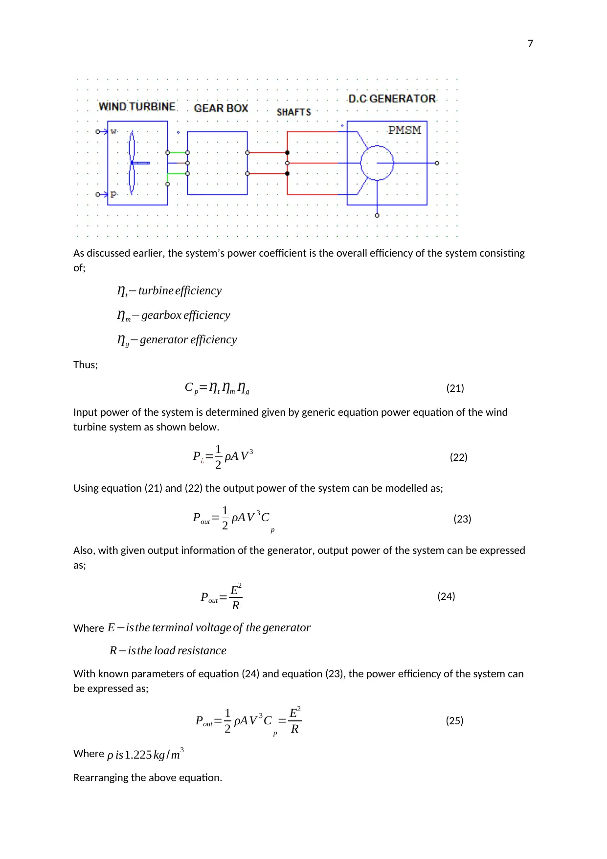
As discussed earlier, the system’s power coefficient is the overall efficiency of the system consisting
of;
Ƞt−turbine efficiency
Ƞm−gearbox efficiency
Ƞg−generator efficiency
Thus;
C p=Ƞt Ƞm Ƞg (21)
Input power of the system is determined given by generic equation power equation of the wind
turbine system as shown below.
P¿=1
2 ρA V 3 (22)
Using equation (21) and (22) the output power of the system can be modelled as;
Pout= 1
2 ρAV 3 C p
(23)
Also, with given output information of the generator, output power of the system can be expressed
as;
Pout= E2
R (24)
Where E−isthe terminal voltage of the generator
R−isthe load resistance
With known parameters of equation (24) and equation (23), the power efficiency of the system can
be expressed as;
Pout= 1
2 ρA V 3 C p
= E2
R (25)
Where ρ is1.225 kg /m3
Rearranging the above equation.
Paraphrase This Document
Need a fresh take? Get an instant paraphrase of this document with our AI Paraphraser
8
C p=2 E2
ρA V 3 R (26)
Recalling TSR of the turbines rotor blades as given by equation (14), shown below.
ʎ = v
V = ωr
V (27)
Replacing angular velocity ω with equivalent RPM of the generator’s rotor.
ω=RPM × 2 π
60 sec (28)
Substituting equation (28) into equation (27).
ʎ = r
V {RPM × 2 π
60 sec } (29)
For different values of speed, following graphs can be plotted.
i. Electrical power output against the wind speed.
ii. Power co-efficiency against the wind speed.
iii. Tips speed ratio (TSR) against power co-efficiency.
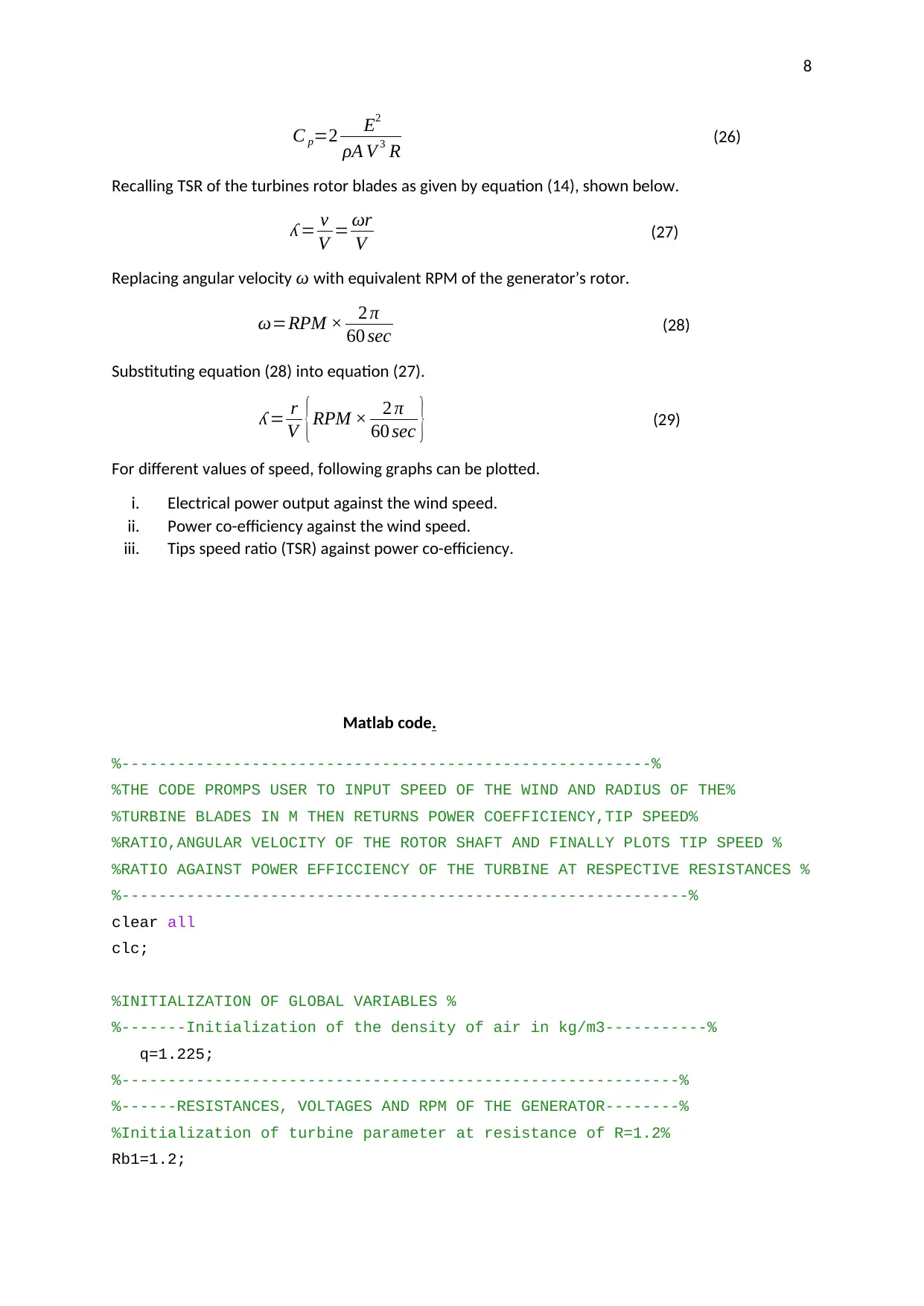
Matlab code.
%---------------------------------------------------------%
%THE CODE PROMPS USER TO INPUT SPEED OF THE WIND AND RADIUS OF THE%
%TURBINE BLADES IN M THEN RETURNS POWER COEFFICIENCY,TIP SPEED%
%RATIO,ANGULAR VELOCITY OF THE ROTOR SHAFT AND FINALLY PLOTS TIP SPEED %
%RATIO AGAINST POWER EFFICCIENCY OF THE TURBINE AT RESPECTIVE RESISTANCES %
%-------------------------------------------------------------%
clear all
clc;
%INITIALIZATION OF GLOBAL VARIABLES %
%-------Initialization of the density of air in kg/m3-----------%
q=1.225;
%------------------------------------------------------------%
%------RESISTANCES, VOLTAGES AND RPM OF THE GENERATOR--------%
%Initialization of turbine parameter at resistance of R=1.2%
Rb1=1.2;
C p=2 E2
ρA V 3 R (26)
Recalling TSR of the turbines rotor blades as given by equation (14), shown below.
ʎ = v
V = ωr
V (27)
Replacing angular velocity ω with equivalent RPM of the generator’s rotor.
ω=RPM × 2 π
60 sec (28)
Substituting equation (28) into equation (27).
ʎ = r
V {RPM × 2 π
60 sec } (29)
For different values of speed, following graphs can be plotted.
i. Electrical power output against the wind speed.
ii. Power co-efficiency against the wind speed.
iii. Tips speed ratio (TSR) against power co-efficiency.
Matlab code.
%---------------------------------------------------------%
%THE CODE PROMPS USER TO INPUT SPEED OF THE WIND AND RADIUS OF THE%
%TURBINE BLADES IN M THEN RETURNS POWER COEFFICIENCY,TIP SPEED%
%RATIO,ANGULAR VELOCITY OF THE ROTOR SHAFT AND FINALLY PLOTS TIP SPEED %
%RATIO AGAINST POWER EFFICCIENCY OF THE TURBINE AT RESPECTIVE RESISTANCES %
%-------------------------------------------------------------%
clear all
clc;
%INITIALIZATION OF GLOBAL VARIABLES %
%-------Initialization of the density of air in kg/m3-----------%
q=1.225;
%------------------------------------------------------------%
%------RESISTANCES, VOLTAGES AND RPM OF THE GENERATOR--------%
%Initialization of turbine parameter at resistance of R=1.2%
Rb1=1.2;
9
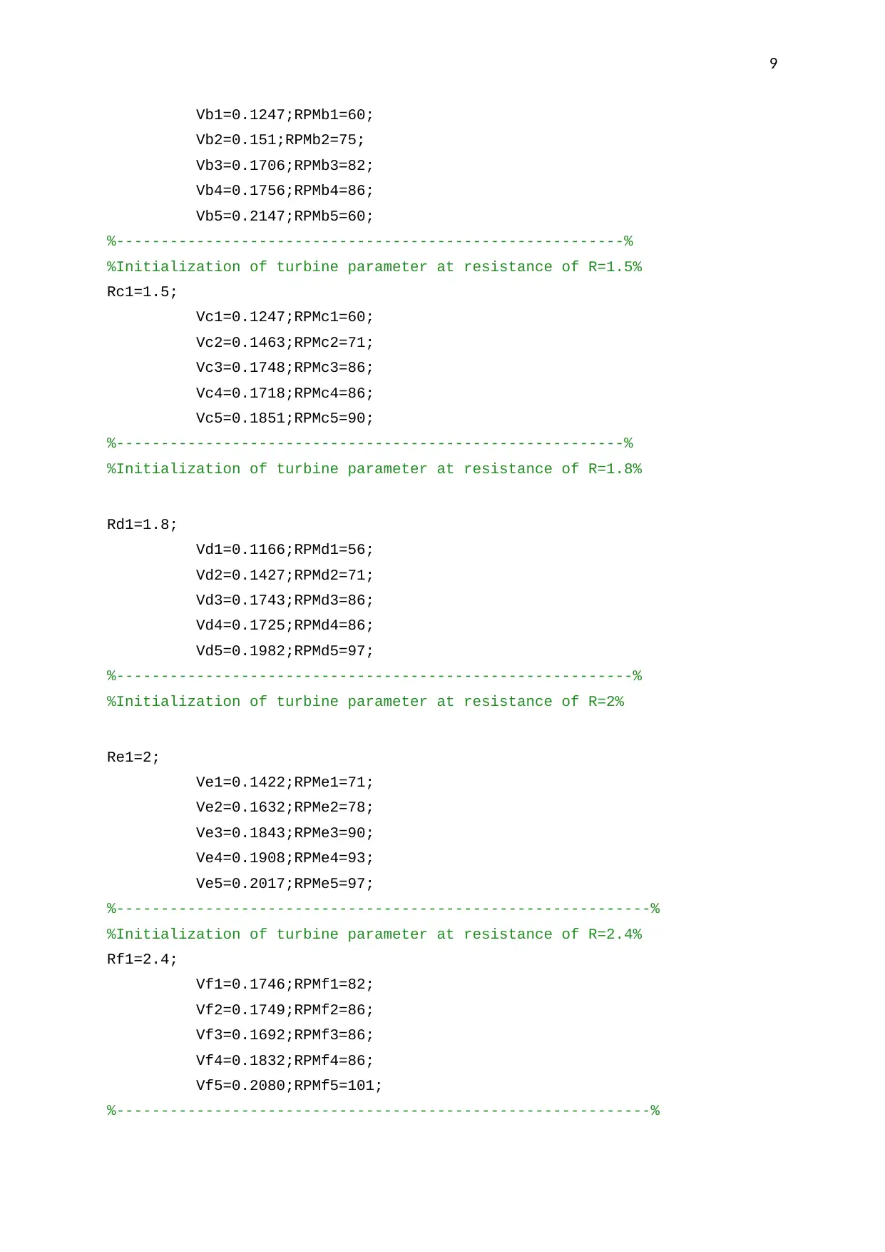
Vb1=0.1247;RPMb1=60;
Vb2=0.151;RPMb2=75;
Vb3=0.1706;RPMb3=82;
Vb4=0.1756;RPMb4=86;
Vb5=0.2147;RPMb5=60;
%---------------------------------------------------------%
%Initialization of turbine parameter at resistance of R=1.5%
Rc1=1.5;
Vc1=0.1247;RPMc1=60;
Vc2=0.1463;RPMc2=71;
Vc3=0.1748;RPMc3=86;
Vc4=0.1718;RPMc4=86;
Vc5=0.1851;RPMc5=90;
%---------------------------------------------------------%
%Initialization of turbine parameter at resistance of R=1.8%
Rd1=1.8;
Vd1=0.1166;RPMd1=56;
Vd2=0.1427;RPMd2=71;
Vd3=0.1743;RPMd3=86;
Vd4=0.1725;RPMd4=86;
Vd5=0.1982;RPMd5=97;
%----------------------------------------------------------%
%Initialization of turbine parameter at resistance of R=2%
Re1=2;
Ve1=0.1422;RPMe1=71;
Ve2=0.1632;RPMe2=78;
Ve3=0.1843;RPMe3=90;
Ve4=0.1908;RPMe4=93;
Ve5=0.2017;RPMe5=97;
%------------------------------------------------------------%
%Initialization of turbine parameter at resistance of R=2.4%
Rf1=2.4;
Vf1=0.1746;RPMf1=82;
Vf2=0.1749;RPMf2=86;
Vf3=0.1692;RPMf3=86;
Vf4=0.1832;RPMf4=86;
Vf5=0.2080;RPMf5=101;
%------------------------------------------------------------%
⊘ This is a preview!⊘
Do you want full access?
Subscribe today to unlock all pages.
Trusted by 1+ million students worldwide
10
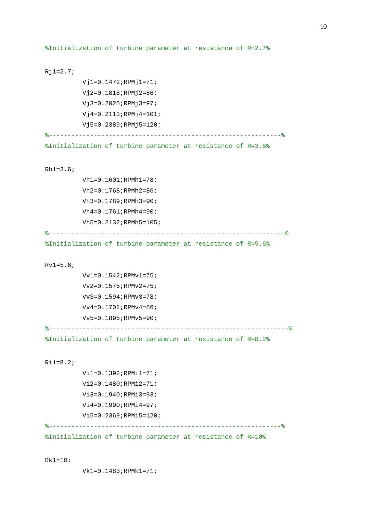
%Initialization of turbine parameter at resistance of R=2.7%
Rj1=2.7;
Vj1=0.1472;RPMj1=71;
Vj2=0.1818;RPMj2=86;
Vj3=0.2025;RPMj3=97;
Vj4=0.2113;RPMj4=101;
Vj5=0.2389;RPMj5=120;
%--------------------------------------------------------------%
%Initialization of turbine parameter at resistance of R=3.6%
Rh1=3.6;
Vh1=0.1601;RPMh1=78;
Vh2=0.1768;RPMh2=86;
Vh3=0.1789;RPMh3=90;
Vh4=0.1761;RPMh4=90;
Vh5=0.2132;RPMh5=105;
%---------------------------------------------------------------%
%Initialization of turbine parameter at resistance of R=5.6%
Rv1=5.6;
Vv1=0.1542;RPMv1=75;
Vv2=0.1575;RPMv2=75;
Vv3=0.1594;RPMv3=78;
Vv4=0.1702;RPMv4=86;
Vv5=0.1895;RPMv5=90;
%----------------------------------------------------------------%
%Initialization of turbine parameter at resistance of R=8.2%
Ri1=8.2;
Vi1=0.1392;RPMi1=71;
Vi2=0.1480;RPMi2=71;
Vi3=0.1940;RPMi3=93;
Vi4=0.1990;RPMi4=97;
Vi5=0.2369;RPMi5=120;
%--------------------------------------------------------------%
%Initialization of turbine parameter at resistance of R=10%
Rk1=10;
Vk1=0.1483;RPMk1=71;
Paraphrase This Document
Need a fresh take? Get an instant paraphrase of this document with our AI Paraphraser
11
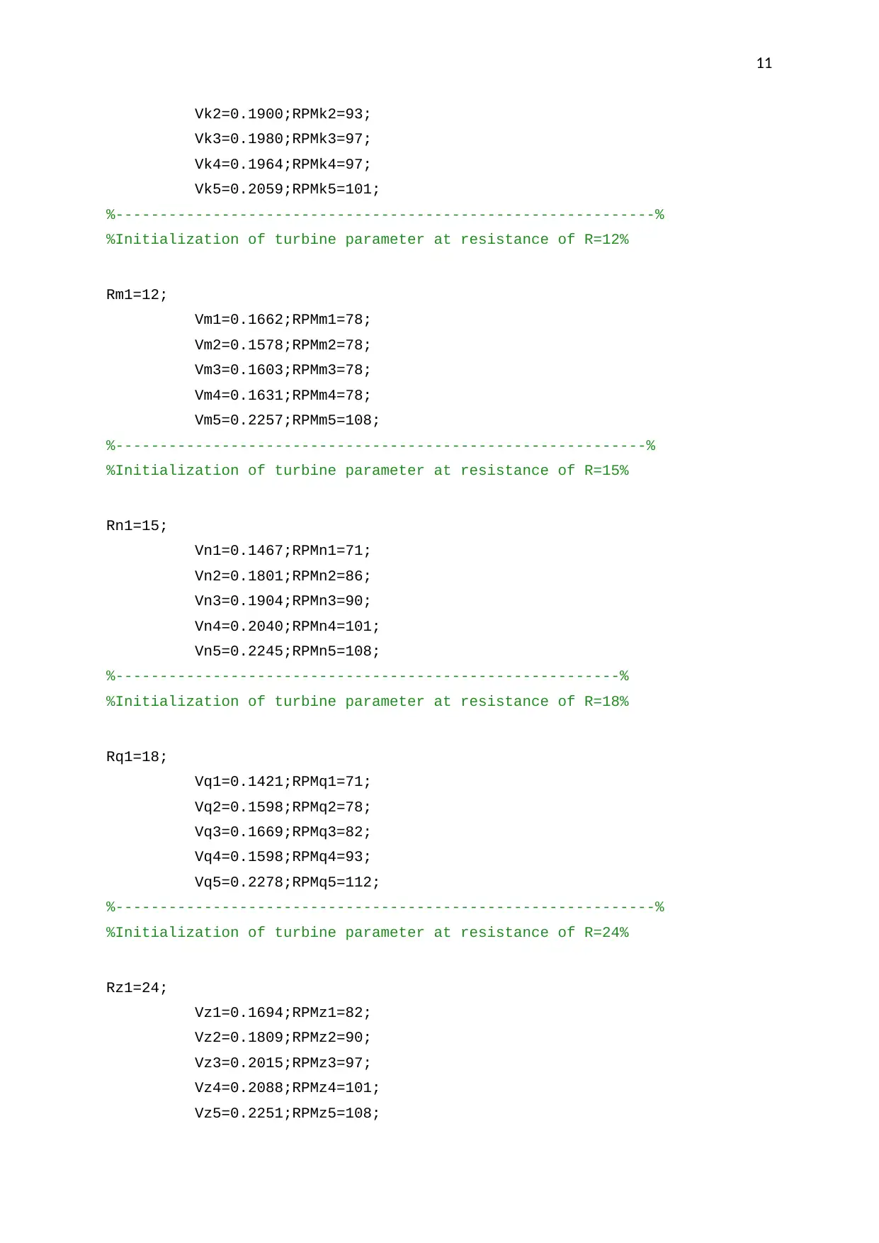
Vk2=0.1900;RPMk2=93;
Vk3=0.1980;RPMk3=97;
Vk4=0.1964;RPMk4=97;
Vk5=0.2059;RPMk5=101;
%-------------------------------------------------------------%
%Initialization of turbine parameter at resistance of R=12%
Rm1=12;
Vm1=0.1662;RPMm1=78;
Vm2=0.1578;RPMm2=78;
Vm3=0.1603;RPMm3=78;
Vm4=0.1631;RPMm4=78;
Vm5=0.2257;RPMm5=108;
%------------------------------------------------------------%
%Initialization of turbine parameter at resistance of R=15%
Rn1=15;
Vn1=0.1467;RPMn1=71;
Vn2=0.1801;RPMn2=86;
Vn3=0.1904;RPMn3=90;
Vn4=0.2040;RPMn4=101;
Vn5=0.2245;RPMn5=108;
%---------------------------------------------------------%
%Initialization of turbine parameter at resistance of R=18%
Rq1=18;
Vq1=0.1421;RPMq1=71;
Vq2=0.1598;RPMq2=78;
Vq3=0.1669;RPMq3=82;
Vq4=0.1598;RPMq4=93;
Vq5=0.2278;RPMq5=112;
%-------------------------------------------------------------%
%Initialization of turbine parameter at resistance of R=24%
Rz1=24;
Vz1=0.1694;RPMz1=82;
Vz2=0.1809;RPMz2=90;
Vz3=0.2015;RPMz3=97;
Vz4=0.2088;RPMz4=101;
Vz5=0.2251;RPMz5=108;
12
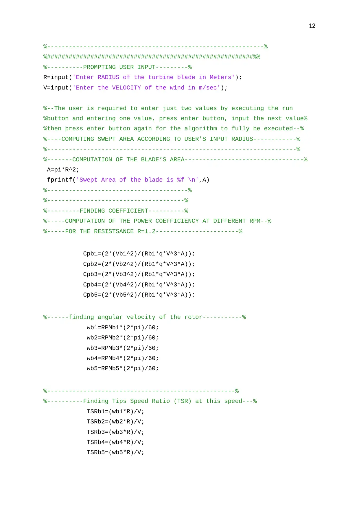
%------------------------------------------------------------%
%#########################################################%%
%----------PROMPTING USER INPUT---------%
R=input('Enter RADIUS of the turbine blade in Meters');
V=input('Enter the VELOCITY of the wind in m/sec');
%--The user is required to enter just two values by executing the run
%button and entering one value, press enter button, input the next value%
%then press enter button again for the algorithm to fully be executed--%
%----COMPUTING SWEPT AREA ACCORDING TO USER'S INPUT RADIUS------------%
%---------------------------------------------------------------------%
%-------COMPUTATION OF THE BLADE’S AREA---------------------------------%
A=pi*R^2;
fprintf('Swept Area of the blade is %f \n',A)
%---------------------------------------%
%--------------------------------------%
%---------FINDING COEFFICIENT----------%
%-----COMPUTATION OF THE POWER COEFFICIENCY AT DIFFERENT RPM--%
%-----FOR THE RESISTSANCE R=1.2-----------------------%
Cpb1=(2*(Vb1^2)/(Rb1*q*V^3*A));
Cpb2=(2*(Vb2^2)/(Rb1*q*V^3*A));
Cpb3=(2*(Vb3^2)/(Rb1*q*V^3*A));
Cpb4=(2*(Vb4^2)/(Rb1*q*V^3*A));
Cpb5=(2*(Vb5^2)/(Rb1*q*V^3*A));
%------finding angular velocity of the rotor-----------%
wb1=RPMb1*(2*pi)/60;
wb2=RPMb2*(2*pi)/60;
wb3=RPMb3*(2*pi)/60;
wb4=RPMb4*(2*pi)/60;
wb5=RPMb5*(2*pi)/60;
%----------------------------------------------------%
%----------Finding Tips Speed Ratio (TSR) at this speed---%
TSRb1=(wb1*R)/V;
TSRb2=(wb2*R)/V;
TSRb3=(wb3*R)/V;
TSRb4=(wb4*R)/V;
TSRb5=(wb5*R)/V;
⊘ This is a preview!⊘
Do you want full access?
Subscribe today to unlock all pages.
Trusted by 1+ million students worldwide
1 out of 31
Related Documents


Your All-in-One AI-Powered Toolkit for Academic Success.
+13062052269
info@desklib.com
Available 24*7 on WhatsApp / Email
![[object Object]](/_next/static/media/star-bottom.7253800d.svg)
Unlock your academic potential
Copyright © 2020–2026 A2Z Services. All Rights Reserved. Developed and managed by ZUCOL.