University Network Design Report: Wireless Call Centre Project

Verified

Added on  2021/04/21

|29
|5007
|380
Report
AI Summary
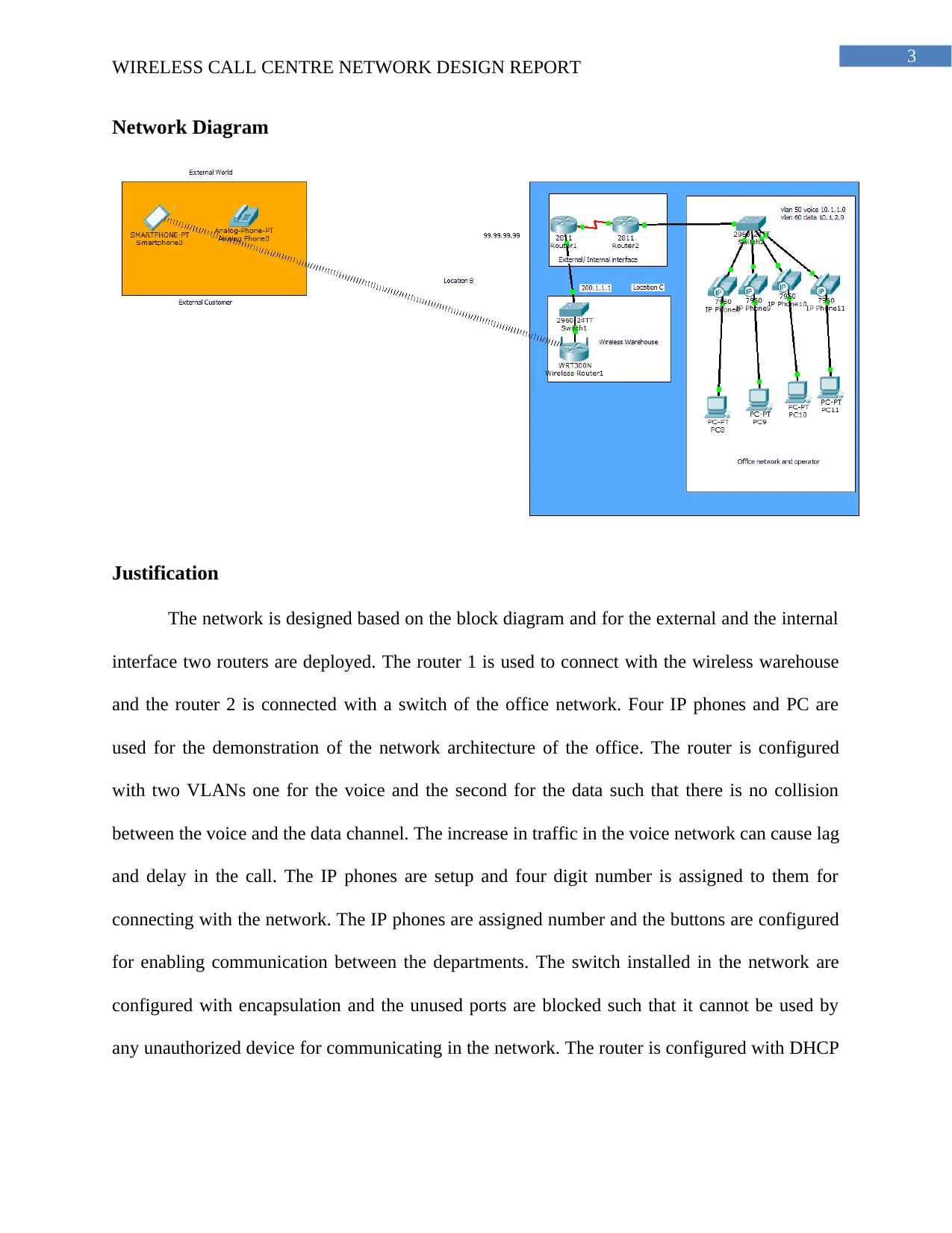
This report presents a detailed design for a wireless call center network for ABC Company, focusing on enhancing the security of voice and data communications. The network design, created using Cisco Packet Tracer, includes two routers, switches, IP phones, and PCs. The report outlines the network diagram, justifications for the design choices, and configurations for both wired and wireless components, including VLAN setup for voice and data separation and the use of the EIGRP routing protocol. It provides evidence of communication through screenshots of successful VoIP calls and detailed configuration commands for routers and switches. The report also addresses factors affecting signal quality and strength, suggesting countermeasures to mitigate interference and improve network efficiency, such as optimal placement of access points and the application of spread spectrum technology. The equipment list includes Cisco routers, IP phones, and switches, among other components required for network implementation.
Document Page
Running head: WIRELESS CALL CENTRE NETWORK DESIGN REPORT
Wireless Call Centre Network Design Report
Name of the Student
Name of the University
Author’s Note
tabler-icon-diamond-filled.svg

Paraphrase This Document

Need a fresh take? Get an instant paraphrase of this document with our AI Paraphraser
Document Page
1
WIRELESS CALL CENTRE NETWORK DESIGN REPORT
Table of Contents
Introduction..........................................................................................................................2
Task A..................................................................................................................................2
Network Diagram............................................................................................................3
Justification......................................................................................................................3
Configuration of the wired and WLAN parts..................................................................4
Evidence of communication............................................................................................5
Equipment required for communication........................................................................21
Task B................................................................................................................................22
Task C................................................................................................................................22
Conclusion.........................................................................................................................24
Bibliography......................................................................................................................26
Document Page
2
WIRELESS CALL CENTRE NETWORK DESIGN REPORT
Introduction
The report is prepared for company ABC for the development of the wireless call center
network design. The network is designed following the requirement and improvement of the
security of the voice and the data communications. The initial plan of the network is followed for
the development of the network and enabling communication between the warehouse and the
external customer. The network solution is created in cisco packet tracer and the devices are
configured for testing the functionality of the network. The commands used for configuration of
the IP phone and the router are attached in the document such that network administrator can
find it easy to configure the hardware device installed in the company’s site. The errors in the
configuration are tested multiple times and the installation location of the routers and the access
points are verified for increasing the security of the network. The network diagram is labelled
with the IP address used for configuring the interface and a justification of the design is given in
the document.
Task A
Document Page
3
WIRELESS CALL CENTRE NETWORK DESIGN REPORT
Network Diagram
Justification
The network is designed based on the block diagram and for the external and the internal
interface two routers are deployed. The router 1 is used to connect with the wireless warehouse
and the router 2 is connected with a switch of the office network. Four IP phones and PC are
used for the demonstration of the network architecture of the office. The router is configured
with two VLANs one for the voice and the second for the data such that there is no collision
between the voice and the data channel. The increase in traffic in the voice network can cause lag
and delay in the call. The IP phones are setup and four digit number is assigned to them for
connecting with the network. The IP phones are assigned number and the buttons are configured
for enabling communication between the departments. The switch installed in the network are
configured with encapsulation and the unused ports are blocked such that it cannot be used by
any unauthorized device for communicating in the network. The router is configured with DHCP
tabler-icon-diamond-filled.svg

Paraphrase This Document

Need a fresh take? Get an instant paraphrase of this document with our AI Paraphraser
Document Page
4
WIRELESS CALL CENTRE NETWORK DESIGN REPORT
with the range of IP address for the different VLANS and the device connected in the network
and automatically assigned with the IP address for enabling the communication.
Explanation of the use of routing protocol
Routing protocol is required for connecting the interfaces of the router 1 and router 2 and
enabling the devices connected at the end of the interface to communicate with the device
installed at the other interface of the second router. The routers are configured with EIGRP
because it consumes less resource and reduces the load on the network. If there is a change in the
topology of the network it can be revised using the new next hop address (Loo, Mauri and Ortiz
2016). Different vlans are created for the data and the voice network and the switch is configured
with the encapsulation and switch port mode access for allowing the device to use the VLAN for
communication (Lo Mills 2016). The default VLAN is used by the trunk port unless the VLAN
is not defined and thus it is important to allow the access of the VLAN to the range of the switch
port such that the data is communicated using the VLAN created for communication of the voice
and the data.
Configuration of the wired and WLAN parts
A wireless router is used and connected with the switch for connecting the wireless
devices in the network. A proper network cabling plan is followed for connecting the routers and
the switches in the network. The IP address used for configuring the devices are used for labeling
the devices in the network diagram. The use of the trunk protocol helps in optimizing the
performance of the access ports and it decreases the time for packet forwarding (Kizza 2017).
The packet are received on the port with the VLAN value added on the header for forwarding it
to the destination address. A point to point link is established between the devices connected in
the network for allowing the different vlans to communicate with each other. The IEEE 802.1 Q
Document Page
5
WIRELESS CALL CENTRE NETWORK DESIGN REPORT
encapsulation is also used for the insertion of the tag about the VLAN and identify the frame and
the packet (Yan and Yu 2015). The encapsulation of the trunk also helps in transmission of the
data packets in the end to end traffic through the network utilizing the same VLAN.
During the configuration of the port using the access mode the VLAN that would be used
for carrying the traffic to that interface needs to be specified. If the VLAN is not defined in the
access mode the default VLAN i.e. VLAN 1 is used for carrying the data traffic (Rautaray and
Agrawal 2015). A new VLAN can be created in the switch and allowed its access unless if the
access port receives the data packet with 802.1Q tag embedded in the header the without learning
the VLAN information the packet is dropped.
Evidence of communication
For providing the evidence of the communication between the devices used for
configuration of the network the following screenshot is attached. For testing the VOIP
connection a call is placed from the IP phone with the assigned phone number and if the call is
successfully established then the VOIP connection is also tested.
Document Page
6
WIRELESS CALL CENTRE NETWORK DESIGN REPORT
Configuration
Router 1 Configuration
Router(config-if)#
Router(config)#int s0/2/0
Router(config-if)#ip add 200.1.1.2 255.255.255.0
Router(config-if)#no shut
Router(config-if)#
%LINK-5-CHANGED: Interface Serial0/2/0, changed state to up
Router(config-if)#exit
Router(config)#
%LINEPROTO-5-UPDOWN: Line protocol on Interface Serial0/2/0, changed state to up
%DUAL-5-NBRCHANGE: IP-EIGRP 1: Neighbor 200.1.1.1 (Serial0/2/0) is up: new
adjacency
Router(config)#router eigrp 1
Router(config-router)#network 192.168.1.0
Router(config-router)#network 192.168.2.0
Router(config-router)#network 200.1.1.0
Router(config-router)#network 99.99.99.99
tabler-icon-diamond-filled.svg

Paraphrase This Document

Need a fresh take? Get an instant paraphrase of this document with our AI Paraphraser
Document Page
7
WIRELESS CALL CENTRE NETWORK DESIGN REPORT
Router(config-router)#network 10.1.1.0
Router(config-router)#network 10.1.2.0
Router(config-router)#exit
Router(config)#int s0/2/0
Router(config-if)#ip add 200.1.1.2 255.255.255.0
Router(config-if)#no shut
Router(config)#int s0/2/1
Router(config-if)#ip add 99.99.99.99 255.255.255.0
Router(config-if)#clock rate 64000
Router(config-if)#no shut
Router(config-if)#
%LINK-5-CHANGED: Interface Serial0/2/1, changed state to up
Router(config-if)#
%LINEPROTO-5-UPDOWN: Line protocol on Interface Serial0/2/1, changed state to up
Router(config-if)#
Router>
Router>en
Document Page
8
WIRELESS CALL CENTRE NETWORK DESIGN REPORT
Router#config t
Enter configuration commands, one per line. End with CNTL/Z.
Router(config)#int f0/0
Router(config-if)#no shut
Router(config-if)#
%LINK-5-CHANGED: Interface FastEthernet0/0, changed state to up
%LINEPROTO-5-UPDOWN: Line protocol on Interface FastEthernet0/0, changed state
to up
Router(config-if)#exit
Router(config)#int f0/0.30
Router(config-subif)#
%LINK-5-CHANGED: Interface FastEthernet0/0.30, changed state to up
%LINEPROTO-5-UPDOWN: Line protocol on Interface FastEthernet0/0.30, changed
state to up
Router(config-subif)#encapsulation dot1Q 30
Router(config-subif)#ip add 192.168.1.1 255.255.255.0
Router(config-subif)#exit
Router(config)#int f0/0.40
Router(config-subif)#
Document Page
9
WIRELESS CALL CENTRE NETWORK DESIGN REPORT
%LINK-5-CHANGED: Interface FastEthernet0/0.40, changed state to up
%LINEPROTO-5-UPDOWN: Line protocol on Interface FastEthernet0/0.40, changed
state to up
Router(config-subif)#encapsulation dot1Q 40
Router(config-subif)#ip add 192.168.2.1 255.255.255.0
Router(config-subif)#exit
Router(config)#
Router(config)#ip dhcp excluded-address 192.168.1.1 192.168.1.10
Router(config)#ip dhcp excluded-address 192.168.2.1 192.168.2.10
Router(config)#ip dhcp pool voice
Router(dhcp-config)#network 192.168.1.0 255.255.255.0
Router(dhcp-config)#default-router 192.168.1.1
Router(dhcp-config)#option 150 ip 192.168.1.1
Router(dhcp-config)#exit
Router(config)#ip dhcp pool data
Router(dhcp-config)#network 192.168.2.1 255.255.255.0
Router(dhcp-config)#default-router 192.168.2.1
Router(dhcp-config)#option 150 ip 192.168.2.1
Router(dhcp-config)#exit
tabler-icon-diamond-filled.svg

Paraphrase This Document

Need a fresh take? Get an instant paraphrase of this document with our AI Paraphraser
Document Page
10
WIRELESS CALL CENTRE NETWORK DESIGN REPORT
Router(config)#telephony-service
Router(config-telephony)#max-dn 10
Router(config-telephony)#max-ephone 10
Router(config-telephony)#ip source-address 192.168.1.1 port 2000
Router(config-telephony)#exit
Router(config)#ephone-dn 1
Router(config-ephone-dn)#%LINK-3-UPDOWN: Interface ephone_dsp DN 1.1, changed
state to up
Router(config-ephone-dn)#number 2001
Router(config-ephone-dn)#exit
Router(config)#ephone-dn 2
Router(config-ephone-dn)#%LINK-3-UPDOWN: Interface ephone_dsp DN 2.1, changed
state to up
Router(config-ephone-dn)#number 2002
Router(config-ephone-dn)#exit
Router(config)#ephone-dn 3
Router(config-ephone-dn)#%LINK-3-UPDOWN: Interface ephone_dsp DN 3.1, changed
state to up
Router(config-ephone-dn)#number 2003
Document Page
11
WIRELESS CALL CENTRE NETWORK DESIGN REPORT
Router(config-ephone-dn)#exit
Router(config)#ephone-dn 4
Router(config-ephone-dn)#%LINK-3-UPDOWN: Interface ephone_dsp DN 4.1, changed
state to up
Router(config-ephone-dn)#number 2004
Router(config-ephone-dn)#exit
Router(config)#
Router(config)#ephone 1
Router(config-ephone)#button 1:1
Router(config-ephone)#
%IPPHONE-6-REGISTER: ephone-1 IP:192.168.1.11 Socket:2 DeviceType:Phone has
registered.
Router(config-ephone)#ephone 2
Router(config-ephone)#button 1:2
Router(config-ephone)#e
%IPPHONE-6-REGISTER: ephone-2 IP:192.168.1.13 Socket:2 DeviceType:Phone has
registered.
Router(config-ephone)#exit
Router(config)#ephone 3
chevron_up_icon
1 out of 29
circle_padding
hide_on_mobile
zoom_out_icon
[object Object]