Wireless Communication and Modulation Techniques Assignment

Verified

Added on  2022/11/16

|15
|2725
|1
Homework Assignment
AI Summary
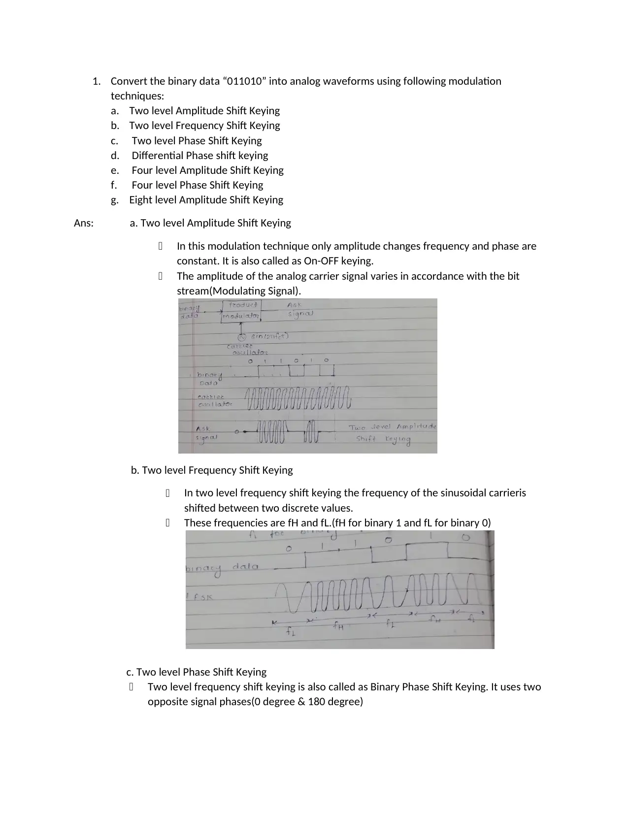
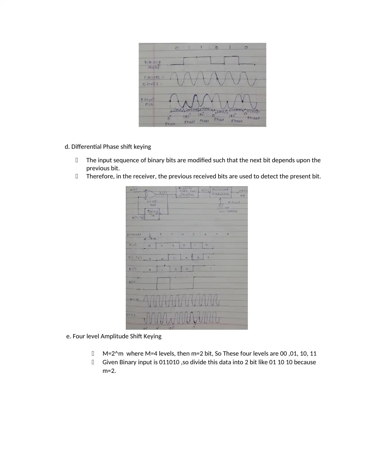
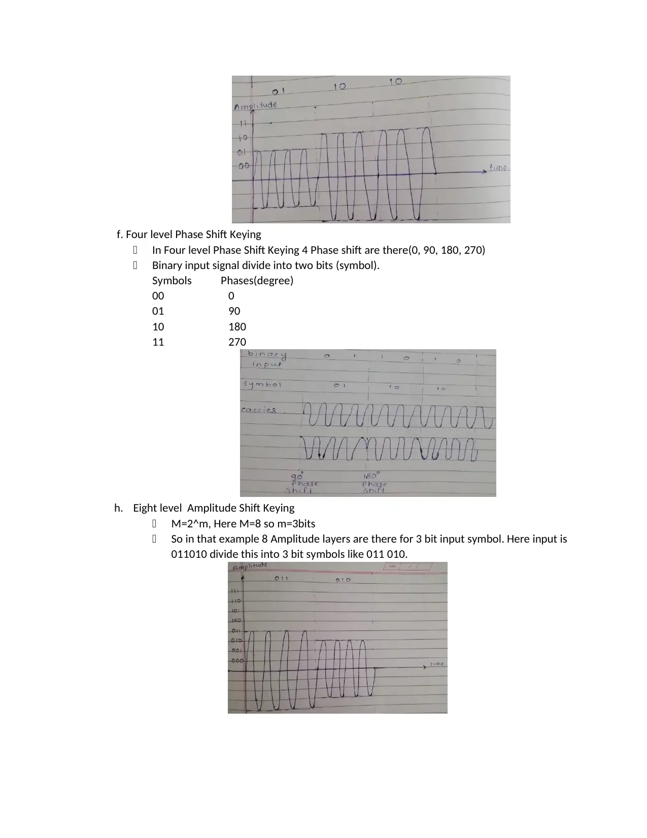
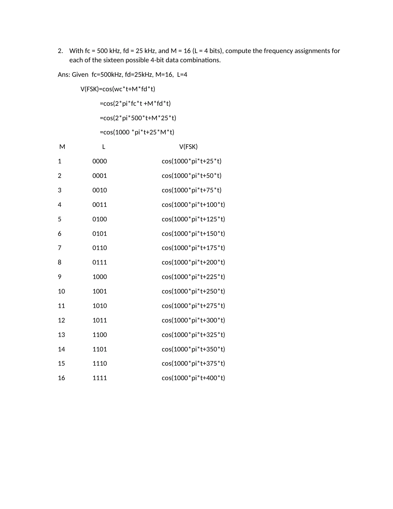
This assignment solution covers various aspects of wireless communication systems. It begins by converting binary data into analog waveforms using different modulation techniques like ASK, FSK, PSK, DPSK, and QAM. The solution then computes frequency assignments for FSK with given parameters and draws analog and frequency modulation waveforms. It includes a 16 QAM constellation diagram and explains the error detection process using Cyclic Redundancy Check (CRC), computing frame check sequences. The solution also computes the transmitted signal using Direct Sequence Spread Spectrum and differentiates between Infrastructure and ad hoc modes in WLAN, including diagrams. Finally, it compares TCP and OSI protocols for wired and wireless LANs using diagrams. The assignment demonstrates a comprehensive understanding of communication systems principles.
Document Page
1. Convert the binary data “011010” into analog waveforms using following modulation
techniques:
a. Two level Amplitude Shift Keying
b. Two level Frequency Shift Keying
c. Two level Phase Shift Keying
d. Differential Phase shift keying
e. Four level Amplitude Shift Keying
f. Four level Phase Shift Keying
g. Eight level Amplitude Shift Keying
Ans: a. Two level Amplitude Shift Keying
In this modulation technique only amplitude changes frequency and phase are
constant. It is also called as On-OFF keying.
The amplitude of the analog carrier signal varies in accordance with the bit
stream(Modulating Signal).
b. Two level Frequency Shift Keying
In two level frequency shift keying the frequency of the sinusoidal carrieris
shifted between two discrete values.
These frequencies are fH and fL.(fH for binary 1 and fL for binary 0)
c. Two level Phase Shift Keying
Two level frequency shift keying is also called as Binary Phase Shift Keying. It uses two
opposite signal phases(0 degree & 180 degree)
tabler-icon-diamond-filled.svg

Paraphrase This Document

Need a fresh take? Get an instant paraphrase of this document with our AI Paraphraser
Document Page
d. Differential Phase shift keying
The input sequence of binary bits are modified such that the next bit depends upon the
previous bit.
Therefore, in the receiver, the previous received bits are used to detect the present bit.
e. Four level Amplitude Shift Keying
M=2^m where M=4 levels, then m=2 bit, So These four levels are 00 ,01, 10, 11
Given Binary input is 011010 ,so divide this data into 2 bit like 01 10 10 because
m=2.
Document Page
f. Four level Phase Shift Keying
In Four level Phase Shift Keying 4 Phase shift are there(0, 90, 180, 270)
Binary input signal divide into two bits (symbol).
Symbols Phases(degree)
00 0
01 90
10 180
11 270
h. Eight level Amplitude Shift Keying
M=2^m, Here M=8 so m=3bits
So in that example 8 Amplitude layers are there for 3 bit input symbol. Here input is
011010 divide this into 3 bit symbols like 011 010.
Document Page
2. With fc = 500 kHz, fd = 25 kHz, and M = 16 (L = 4 bits), compute the frequency assignments for
each of the sixteen possible 4-bit data combinations.
Ans: Given fc=500kHz, fd=25kHz, M=16, L=4
V(FSK)=cos(wc*t+M*fd*t)
=cos(2*pi*fc*t +M*fd*t)
=cos(2*pi*500*t+M*25*t)
=cos(1000 *pi*t+25*M*t)
M L V(FSK)
1 0000 cos(1000*pi*t+25*t)
2 0001 cos(1000*pi*t+50*t)
3 0010 cos(1000*pi*t+75*t)
4 0011 cos(1000*pi*t+100*t)
5 0100 cos(1000*pi*t+125*t)
6 0101 cos(1000*pi*t+150*t)
7 0110 cos(1000*pi*t+175*t)
8 0111 cos(1000*pi*t+200*t)
9 1000 cos(1000*pi*t+225*t)
10 1001 cos(1000*pi*t+250*t)
11 1010 cos(1000*pi*t+275*t)
12 1011 cos(1000*pi*t+300*t)
13 1100 cos(1000*pi*t+325*t)
14 1101 cos(1000*pi*t+350*t)
15 1110 cos(1000*pi*t+375*t)
16 1111 cos(1000*pi*t+400*t)
tabler-icon-diamond-filled.svg

Paraphrase This Document

Need a fresh take? Get an instant paraphrase of this document with our AI Paraphraser
Document Page
3. Draw the approximate Analog Modulation and Frequency Modulation waveforms in complete
steps for the following signal:
Amplitude Modulation for input signal:
In Amplitude Modulation amplitude changes according to input signal & frequency and
phase constant.
Frequency Modulation for input signal
In this case, the amplitude of the modulated signal is constant, but its frequency
changes. All the power transmitted in frequency modulation is useful whereas in
amplitude modulation most of the power in carrier (which is useless).
Document Page
4. Draw the 16 QAM Constellation Diagram having two different amplitude levels and eight
different phase levels.
In Quadrature Amplitude Modulation both amplitude and phase changes according to
the input signal.
By using higher order modulation technique like 16 QAM i.e more points on the
constellation, it is possible to transmit more bits per symbol. However points are closer
together & they are therefore more susceptible to noise and data errors.
Bellow Figure shows the constellation diagram and in table shows amplitude and phase
angles.
Document Page
5. Explain and draw the Error Detection Process for Cyclic Redundancy Check (CRC).
Ans:
Cyclic redundancy check is the powerful error detection technique. It is based on binary
division.
CRC generator is an algebraic polynomial represented as a bit pattern.
Consider the CRC generator is
X^6+x^4+x^3+x+1
So binary pattern is
1*x^6 +0*x^5+1*x^4+1*x^3+0*x^2+1*x^1+1*x^0
1011011
The algebraic polynomial chosen as CRC generator should not be divisible by (x+1).
CRC is powerful because it can detect all single bit errors also it can detect most of the larger
burst errors with a high probability.
CRC can detect all burst error of length less than the degree of the polynomial.
Error detection process for CRC
For Example,
Bit stream is 1010101010
Generator polynomial is
x^4 + x^3 + 1
So binary pattern is
= 1*x^4 + 1*x^3 + 0*x^2 + 0*x^1 + 1*x^0
=11001 (Divisor)
The generator polynomial consist of 5 bits so string of a 4 zero’s is appended to the bit
stream to be transmitted.
So the resulting bit stream is 10101010100000
Now binary division performed as
tabler-icon-diamond-filled.svg

Paraphrase This Document

Need a fresh take? Get an instant paraphrase of this document with our AI Paraphraser
Document Page
From here, CRC = 0010
The code to be transmitted is obtained by replacing last 4 zero’s of 10101010100000
with CRC.
So, the code transmitted to the receiver is 10101010100010.
Document Page
6. Compute the frame check sequence for the following information: Message = 10111100, Pattern
= 11011 .
Ans:
Most common frame check sequence algorithm is Cyclic Redundancy Check algorithm.
So ,here we are using CRC algorithm
Bit stream is 10111100
Divisor= 11011
Divisor consist of 5 bits so string of a 4 zero’s is appended to the bit stream to be
transmitted.
So the resulting bit stream is 101111000000
Now binary division performed as
From here, CRC = 0010
The code to be transmitted is obtained by replacing last 4 zero’s of 101111000000 with
CRC.
So, the code transmitted to the receiver is 101111000010.
Document Page
7. Compute the transmitted signal using Direct Sequence Spread Spectrum for the following
information: Input: 1011, Locally Generated PN bit stream: 101011011010, T = 3Tc
Ans:
The most important advantage of spread spectrum modulation is that it provide
protection against externally generated interfering signals called jamming signals.
The averaging system reduce the interference by averaging it over a longer period. The
Direct Sequence Spread Spectrum is averaging system.
Spread spectrum signal m(t)= Binary NRZ sequence b(t)* PN sequence c(t)
In DSSS PN sequence of large bandwidth is multiplied with narrow band data signal.
tabler-icon-diamond-filled.svg

Paraphrase This Document

Need a fresh take? Get an instant paraphrase of this document with our AI Paraphraser
Document Page
8. What is the difference between Infrastructure and ad hoc modes in WLAN? Draw their relative
diagrams as well.
Ans:
In adhoc mode WLAN wireless network is composed of only stations.
In Infrastructure mode WLAN network is composed of stations as well as one OR more
access points.
In adhoc mode the network system that is station communicate directly with one
another .it is also related as independent basic service set OR peer to peer mode.
In Infrastructure mode the device access point is like base stations which is used in
celluar system . All the communication in this mode between stations will go through
access points.
In adhoc mode no physical infrastructure is needed.
In infrastructure mode physical infrastructure is needed.
In most adhoc based WLAN connection MAC protocols (e.g CSMA) are used.
In Infrastructure based WLAN TDMA based protocols are used.
Adhoc mode is suitable for quick wireless connection setup in office rooms, hotels or in
places where wired infrastructure is not available.
In adhoc mode communication is directly over wireless radio waves.
Above fig shows Infrastructure mode ,here access point like a router & all PCs
communicate via access points.
Here access point role is to convert LAN protocol into 802.11 protocol relay to all
stations.
9. Compare the differences of TCP and OSI protocols for wired and wireless LANs using diagrams.
Document Page
Ans:
OSI Model Layers:
OSI stands for Open Systems Interconnection. It is created by the International
Organization for standardization. It enables diverse communication systems to
communicate using standard protocols. Seven Layers in OSI model.
TCP/IP model layers:
It stands for Transmission Control Protocol/Internet Protocol. The TCP/IP model is a
concise version of the OSI model. It contains four layers, unlike seven layers in the OSI
model.
Network Access Layer:
A network layer is the lowest layer of the TCP/IP model. A network layer is the
combination of the Physical layer and Data Link layer defined in the OSI reference model.
chevron_up_icon
1 out of 15
circle_padding
hide_on_mobile
zoom_out_icon
[object Object]