University Wireless Networks and Communication Assignment Solution
VerifiedAdded on 2022/12/14
|15
|2834
|408
Homework Assignment
AI Summary
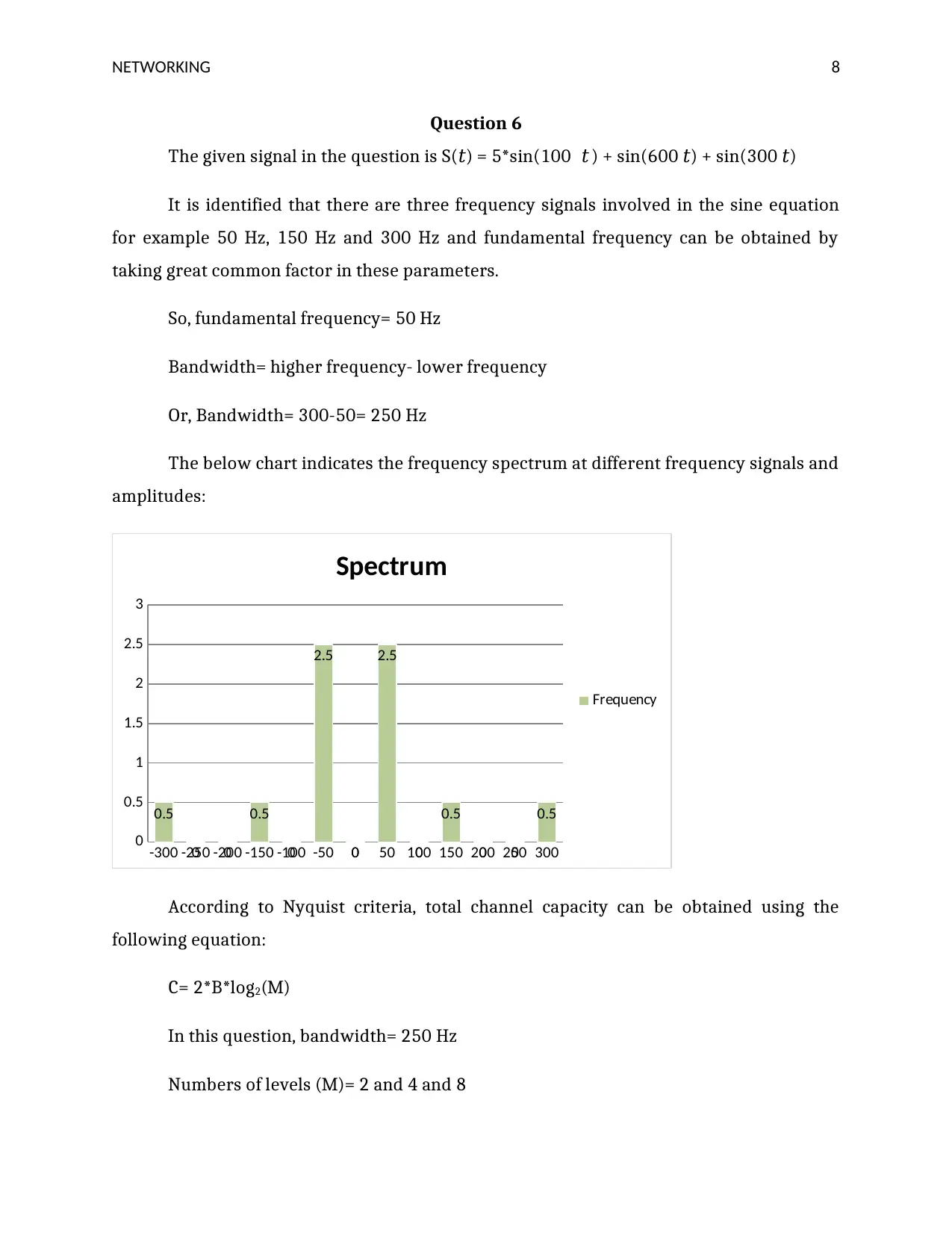
This document provides a comprehensive solution to a wireless networks and communication assignment, covering key concepts and calculations. It begins with an analysis of the TCP/IP model, exploring its layers and functionalities, particularly focusing on the IP and network access layers. The solution then addresses a communication scenario involving prime ministers and translators, illustrating data transmission processes. Following this, the assignment delves into waveform analysis, presenting calculations for amplitude, time period, frequency, and phase for various waveforms. Furthermore, it includes calculations for free space loss at a given frequency and analyzes a signal equation to determine its fundamental frequency and bandwidth, along with channel capacity calculations using the Nyquist criteria. The solution also explains the Nyquist theorem and the impact of levels on data rate. Finally, it contrasts packet switching and circuit switching techniques and addresses antenna height calculations and the factors influencing them.

NETWORKING 0
Wireless network and
communication
Wireless network and
communication
Paraphrase This Document
Need a fresh take? Get an instant paraphrase of this document with our AI Paraphraser

NETWORKING 1
Question 1
TCP/IP is defined as a suite of communication networks which is mainly used for
connecting networking devices on the internet. Such kind of suite may be utilized as a
communication protocol in the private networks. It is identified that there are major four
layers included in the TCP/IP model which are described below:
Application layer
Transport layer
Internet layer
Network access layer
The IP layer is defined as an internet protocol layer which defines the network
protocols used in the communication systems and devices (Fall, & Stevens, 2011). The
major function of the IP layer is to identify which protocol is responsible for the logical
transmission of signals over the complete network. While the network access layer is the
combination of the physical and data link layer of the OSI model. The major function of this
layer is to control the physical connection between the networks and handle the entire
communication system (Goralski, 2017). A recent study argued that IP layer has the
capability to pack signals into small data packets which are called as IP datagrams but
network access layer is able to identify the physical connection between the networks and
identify how bits are electrically signalled using computer devices. As compared to the
network access layer, the IP layer is more effective and reliable but the network access
layer helps the consumers for defining how the message is physically transferred through
the computing network.
Ensafi, Knockel, Alexander, & Crandall, (2014) examined that in the network access
layer the control information is embedded using various protocols including Ethernet,
token ring, and frame relay and so on. However, in IP layer control information is
embedded with the help of IP, ICMP, RARP and ARP. The internet layer is mainly
responsible for the routing of IP datagrams but network access is responsible for the
transmission of a message between two computing devices on the common network

NETWORKING 2
(Acharya, & Tiwari, 2016). Therefore, it is stated both IP and network access layer plays
effective roles in the communication networks by which the consumers can easily perform
data transmission over the computing networks.
Question 2
In the provided scenario, both prime ministers need to communicate with each
other using the telephone and English translator that convert signals into the English
language. The below diagram indicates the interconnection between the French and
Chinese prime ministers:
It is evaluated that when French prime minister performs communication activities
then he addresses his remarks to the Chinese prime minister that help in the transmission
of data. However, the signal is mainly transmitted through major two translators using
mobile phones. The translator adopted by French PM translates his remarks or comments
into English language and send these signals to the translator of Chinese PM using
telephone lines. It is observed that an intermediate node serves to translate the signal
before passing it on and Chinese PM uses a translator that directly remarks into the
Chinese language. Therefore, it is reported that the translator is able to convert the
transmitted signals into another form that helps the receiver for obtaining reliable and
effective information.
Question 3
In this question, there are three waveforms provided in which x-axis shows the time
in seconds and Y-axis indicates the amplitude. Therefore, the asked values are highlighted
below:
⊘ This is a preview!⊘
Do you want full access?
Subscribe today to unlock all pages.

Trusted by 1+ million students worldwide

NETWORKING 3
Points Value
Amplitude 15
Time period 3 sec
Frequency 1/3 Hz
Phase 00
Points Value
Amplitude 4
Time period 6.5 sec
Frequency 1/6.5 Hz
Phase 00
Points Value
Amplitude 15
Time period 3 sec
Frequency 1/3 Hz
Phase 00
Points Value
Amplitude 4
Time period 6.5 sec
Frequency 1/6.5 Hz
Phase 00
Paraphrase This Document
Need a fresh take? Get an instant paraphrase of this document with our AI Paraphraser

NETWORKING 4
Points Value
Amplitude 7.8
Time period 2.3 sec
Frequency 1/2.3 Hz
Phase 900
Question 4
Part A:
After analyzing the above equation, it is identified that there is no phase difference
presented in the signal that means the waveform will be started from the origin. The
remaining values are highlighted below:
Factors Value
Amplitude 3
Frequency 200 Hz
Time period 1/200 sec.
Phase 00

NETWORKING 5
1 229 457 685 913 11411369
-4.00000
-3.00000
-2.00000
-1.00000
0.00000
1.00000
2.00000
3.00000
4.00000
Chart Title
time
y
Axis Title
Part B:
Parts Value
Amplitude 14
Frequency 50 Hz
Time period 1/50 sec.
Phase 90 degree
0.00020.0025 0.0048 0.0071 0.0094 0.01170.0140 0.0163 0.0186
-20.00000
-15.00000
-10.00000
-5.00000
0.00000
5.00000
10.00000
15.00000
20.00000
Y
Y
Part three:
Points Value
Amplitude 4
Frequency 325 Hz
⊘ This is a preview!⊘
Do you want full access?
Subscribe today to unlock all pages.

Trusted by 1+ million students worldwide

NETWORKING 6
Time period 1/325 sec.
Phase 180 degree
1 24 47 70 93 116 139 162 185 208 231 254 277
-5
-4
-3
-2
-1
0
1
2
3
4
5
time
y
Part fourth:
Points Value
Amplitude 6
Frequency 350 Hz
Time period 1/350 sec.
Phase 270 degree
Time period 1/325 sec.
Phase 180 degree
1 24 47 70 93 116 139 162 185 208 231 254 277
-5
-4
-3
-2
-1
0
1
2
3
4
5
time
y
Part fourth:
Points Value
Amplitude 6
Frequency 350 Hz
Time period 1/350 sec.
Phase 270 degree
Paraphrase This Document
Need a fresh take? Get an instant paraphrase of this document with our AI Paraphraser

NETWORKING 7
1 16 31 46 61 76 91 106121136151166181196
-8
-6
-4
-2
0
2
4
6
8
time
y
Therefore, the above all graphs represents the given equations which can help the readers
for understanding the concept behind sinusoidal signals.
Question 5
In the provided information, isotropic free space loss needs to be calculated at the
given data:
Frequency= 6 GHz
Shortest path= 35,863 KM
From the previous study, it is found that total free space loss can be obtained using
the below equation:
20log10 (F) +20log10 (D) - 147.56 dB
In this question, F= 6 GHz and D= 35863 kilometre
Put these values in the above formula in order to gather free space loss
20log10 (6*109) +20log10 (35.863*106) - 147.56 dB
By solving the above problem, it is determined that total free space loss is 199.09 dB
at 6 GHz frequency.

NETWORKING 8
Question 6
The given signal in the question is S(𝑡) = 5*sin(100𝜋 𝑡 ) + sin(600𝜋𝑡) + sin(300𝜋 )𝑡
It is identified that there are three frequency signals involved in the sine equation
for example 50 Hz, 150 Hz and 300 Hz and fundamental frequency can be obtained by
taking great common factor in these parameters.
So, fundamental frequency= 50 Hz
Bandwidth= higher frequency- lower frequency
Or, Bandwidth= 300-50= 250 Hz
The below chart indicates the frequency spectrum at different frequency signals and
amplitudes:
-300 -250 -200 -150 -100 -50 0 50 100 150 200 250 300
0
0.5
1
1.5
2
2.5
3
0.5
0 0
0.5
0
2.5
0
2.5
0
0.5
0 0
0.5
Spectrum
Frequency
According to Nyquist criteria, total channel capacity can be obtained using the
following equation:
C= 2*B*log2(M)
In this question, bandwidth= 250 Hz
Numbers of levels (M)= 2 and 4 and 8
⊘ This is a preview!⊘
Do you want full access?
Subscribe today to unlock all pages.

Trusted by 1+ million students worldwide

NETWORKING 9
So, putting values of M and bandwidth total channel capacity may be calculated
which is given as:
At M= 2 and B= 250
C= 2*250*log2(2)
C=500 bits/s/Hz
At M= 4 and B= 250 Hz
C= 2*250*log2(4)
C=1000 bits/s/Hz
At M= 8 and B= 250 Hz
C= 2*250*log2(8)
C=1500 bits/s/Hz
Question 7
According to Nyquist theorem, data rate over the channel is completely depended
on the bandwidth of a signal and numbers of levels used in the system and total channel
capacity is given as:
C= 2*B*log2(M)
So, in this question, the data rate can be enhanced using bandwidth and numbers of
levels. It is suggested that the users can increase the data rate of the signal by adding
numbers of levels in the system but the key drawback of this process is that it reduces
overall reliability of the system and lead stability related issues in the system.
Paraphrase This Document
Need a fresh take? Get an instant paraphrase of this document with our AI Paraphraser

NETWORKING 10
Question 8
Packet switching and circuit switching
Packet switching and circuit switching are common switching techniques which are
mainly utilized for connecting the numbers of devices with each other. It is observed that
Circuit Switching was especially intended for voice correspondence and it was less
reasonable for information transmission. Thus, a superior arrangement developed for
information transmission called Packet exchanging. The principle distinction between
circuit exchanging and bundle exchanging is that Circuit Switching is association arranged
though; Packet Switching is connectionless (Das, et al., 2010).
Circuit Switching sets up a physical way between the sender and collector of the
message before a message is conveyed. At the point when an association is set up between
a sender and a collector, the whole message goes through the setup way from sender to the
recipient. When the message is conveyed to the collector, the source educates the system
about the finishing regarding transmission and every one of the switches discharged
(Porter, et al., 2010).
Packet Switching is connectionless as it doesn't set up any physical association
before the transmission begins. In bundle exchanging before the message is transmitted, it
is partitioned into some sensible parts called parcels. These parcels are directed
individually from source to goal. In parcel exchanging, every bundle may pursue an
alternate course to arrive at the goal (Kitayama, et al., 2015). Parcels touched base at the
goal are out of request, to be that as it may, they are gathered all together before the goal
forward it to the upper layer.
Circuit Switching is association arranged that implies a way is built up among source
and goal before the transmission happens (Liu, et al., 2014). Then again, Packet Switching
is Connectionless that implies a unique course is chosen for every parcel while
transmission. Circuit Switching was initially intended for voice correspondence while
Packet Switching was initially intended for information correspondence. Circuit Switching
is firm as once a way is built up for transmission, it doesn't change while the span of the
session (Perelló, ett al., 2010).

NETWORKING 11
Then again, Packet Switching is adaptable as every parcel may go through an
alternate course to arrive at its goal. In bundle exchanging, as every parcel ventures an
alternate way thus, the bundle are gotten out of request at the recipient side and later
masterminded all together. Then again, in-circuit exchanging the whole message is gotten
all things considered as sent from a sender to collector (Yoo, 2010). Space Division
Switching or Time-Division Switching can be utilized to execute Circuit Switching though,
Packet Switching can be actualized utilizing two methodologies Datagram Approach and
Virtual Circuit Approach (Takuno, Koyama, & Hikihara, 2010).
Circuit switching and packet exchanging are the two most famous techniques for
exchanging. In-circuit exchanging, information is moved on a devoted channel that will be
set up between the sender and the recipient utilizing a committed point-to-point
association (Kitayama, et al., 2015). In packet exchanging, information is part into little
units called parcels with every parcel being related with a header containing flagging data
about the source and goal hubs. The parcels are transmitted freely and are prepared at all
moderate hubs before arriving at their goal (Chen, et al., 2014).
Question 9
According to this question, the height of the transmitter antenna is 4 times of the
receiver antenna that means H1= 4*H2 and the total distance between these antennas is 60
kilometre.
D= 3.57*sqrt(kh1+kh2)
The above formula will help for determining the heights of each antenna where k=
1.3 and D= 60 km
60 km= 3.57*sqrt(1.3(5H2))
Or, H2= 42.369 meter and H1= 169.476 meter
⊘ This is a preview!⊘
Do you want full access?
Subscribe today to unlock all pages.

Trusted by 1+ million students worldwide
1 out of 15
Related Documents

Your All-in-One AI-Powered Toolkit for Academic Success.
+13062052269
info@desklib.com
Available 24*7 on WhatsApp / Email
Unlock your academic potential
Copyright © 2020–2025 A2Z Services. All Rights Reserved. Developed and managed by ZUCOL.