MITS5003 - Wireless Networks: Encoding, Multiplexing & Communication
VerifiedAdded on 2023/06/10
|17
|3541
|440
Homework Assignment
AI Summary
This assignment delves into the fundamental aspects of wireless networks and communication, focusing on encoding, error control, flow control, multiplexing, and multiple access techniques. It begins with a practical problem concerning a micro robot design, requiring the calculation of data rates and the application of encoding schemes like NRZ-I, Manchester Encoding, and Differential Encoding. The assignment further explores error detection using CRC, and other error control methods such as Hamming code, backward error control, and forward error control. Additionally, it discusses flow control techniques like sliding windows (GBN) and Stop and Wait. The second part of the assignment covers multiplexing techniques, including FDMA, TDMA, and CDMA, explaining their principles and illustrating them with diagrams. This comprehensive analysis provides a solid understanding of the key concepts in wireless network design and communication.
WIRELESS NETWORKS AND COMMUNICATION
[Author Name(s), First M. Last, Omit Titles and Degrees]
[Institutional Affiliation(s)]
[Author Name(s), First M. Last, Omit Titles and Degrees]
[Institutional Affiliation(s)]
Paraphrase This Document
Need a fresh take? Get an instant paraphrase of this document with our AI Paraphraser
Part I: Encoding and error control
a) The data rate required for the robot to the remote controller communication
The data rate formula is found by the number of bits that go through the network in bits
per second
Bits sent=Sum of all each of the units=4+6+4+2=16 bits
The 16 bits have been sent in 2 seconds thus the number of bits in 1 second is given by
=16/2=8 bps
b) Explain 3 types of suitable encoding techniques could be used to encode the status string
One of the most likely important requirements for the design would be an encoding scheme with
a high efficiency in terms of the bandwidth and higher effectiveness for the purposes of the wire
communication and thus the following could be treated as of higher efficiency in relation to
encoding the bit strings (Jafarzadeh, Palesi, Khademzadeh, & Afzali-Kusha, 2014).
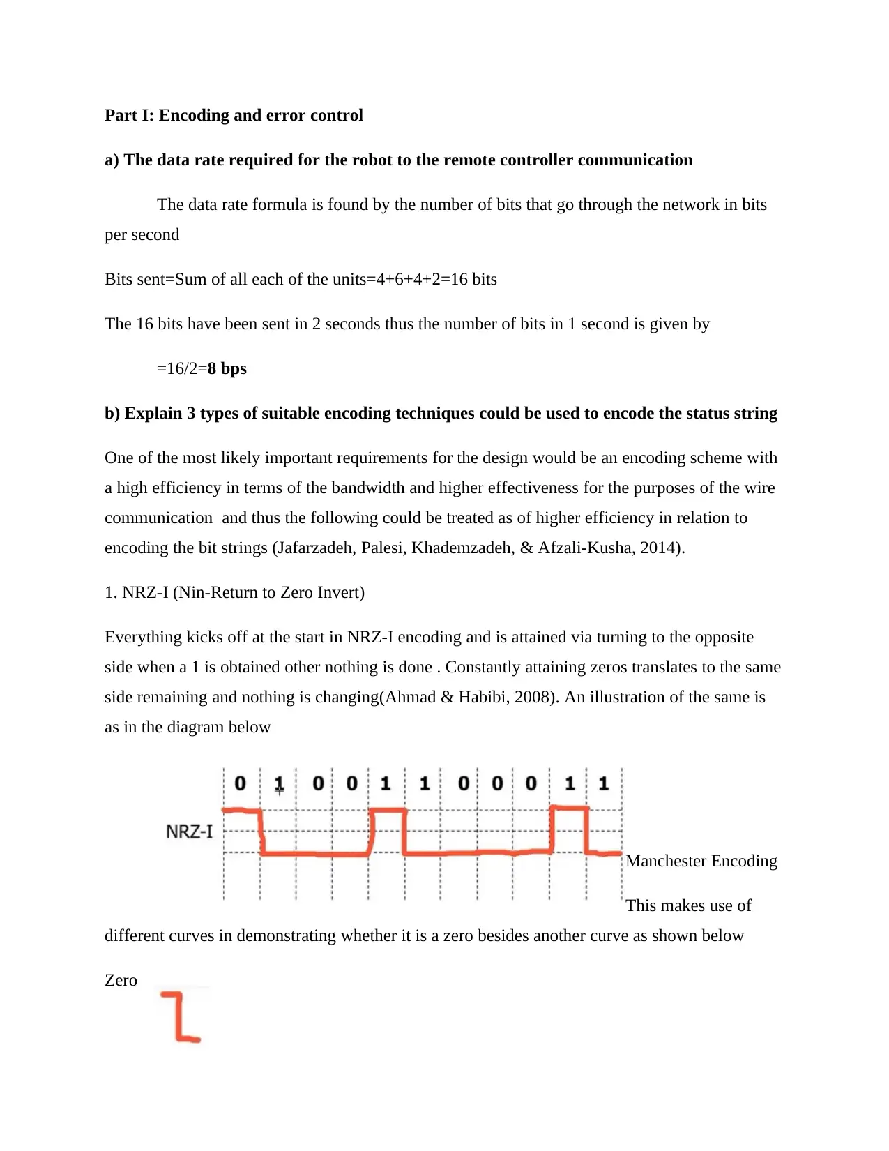
1. NRZ-I (Nin-Return to Zero Invert)
Everything kicks off at the start in NRZ-I encoding and is attained via turning to the opposite
side when a 1 is obtained other nothing is done . Constantly attaining zeros translates to the same
side remaining and nothing is changing(Ahmad & Habibi, 2008). An illustration of the same is
as in the diagram below
Manchester Encoding
This makes use of
different curves in demonstrating whether it is a zero besides another curve as shown below
Zero
a) The data rate required for the robot to the remote controller communication
The data rate formula is found by the number of bits that go through the network in bits
per second
Bits sent=Sum of all each of the units=4+6+4+2=16 bits
The 16 bits have been sent in 2 seconds thus the number of bits in 1 second is given by
=16/2=8 bps
b) Explain 3 types of suitable encoding techniques could be used to encode the status string
One of the most likely important requirements for the design would be an encoding scheme with
a high efficiency in terms of the bandwidth and higher effectiveness for the purposes of the wire
communication and thus the following could be treated as of higher efficiency in relation to
encoding the bit strings (Jafarzadeh, Palesi, Khademzadeh, & Afzali-Kusha, 2014).
1. NRZ-I (Nin-Return to Zero Invert)
Everything kicks off at the start in NRZ-I encoding and is attained via turning to the opposite
side when a 1 is obtained other nothing is done . Constantly attaining zeros translates to the same
side remaining and nothing is changing(Ahmad & Habibi, 2008). An illustration of the same is
as in the diagram below
Manchester Encoding
This makes use of
different curves in demonstrating whether it is a zero besides another curve as shown below
Zero
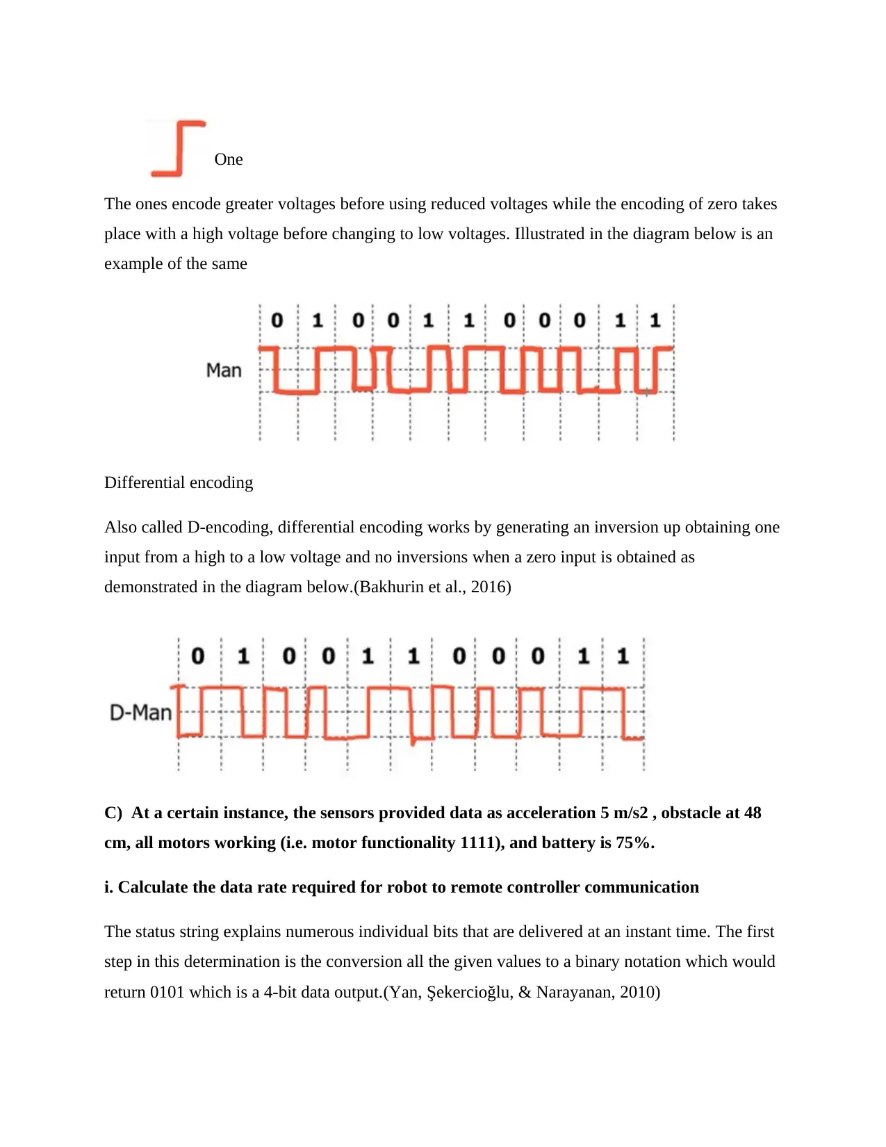
One
The ones encode greater voltages before using reduced voltages while the encoding of zero takes
place with a high voltage before changing to low voltages. Illustrated in the diagram below is an
example of the same
Differential encoding
Also called D-encoding, differential encoding works by generating an inversion up obtaining one
input from a high to a low voltage and no inversions when a zero input is obtained as
demonstrated in the diagram below.(Bakhurin et al., 2016)
C) At a certain instance, the sensors provided data as acceleration 5 m/s2 , obstacle at 48
cm, all motors working (i.e. motor functionality 1111), and battery is 75%.
i. Calculate the data rate required for robot to remote controller communication
The status string explains numerous individual bits that are delivered at an instant time. The first
step in this determination is the conversion all the given values to a binary notation which would
return 0101 which is a 4-bit data output.(Yan, Şekercioğlu, & Narayanan, 2010)
⊘ This is a preview!⊘
Do you want full access?
Subscribe today to unlock all pages.
Trusted by 1+ million students worldwide
The reading of the accelerometer is m/s2
Detection of an obstacle by an ultrasound takes place at 48 cm which upon conversion to binary
notation returns
110000 which is a 6-bit input
The report of the motor status is provided in binary notation already which is 1111
The battery level is provided as 75%, in other words, 0.75 in decimal notation which when
converted to binary notation returns 0.11 .
The array of each of the output data gives the aggregated status stream which is as illustrated
Status string=0101+110000+111+0.11 which returns
0101110000111111 and hence the status string in the binary is given by
0101110000111111
ii. Represent the status string on ASK, FSK, and PSK encoding techniques
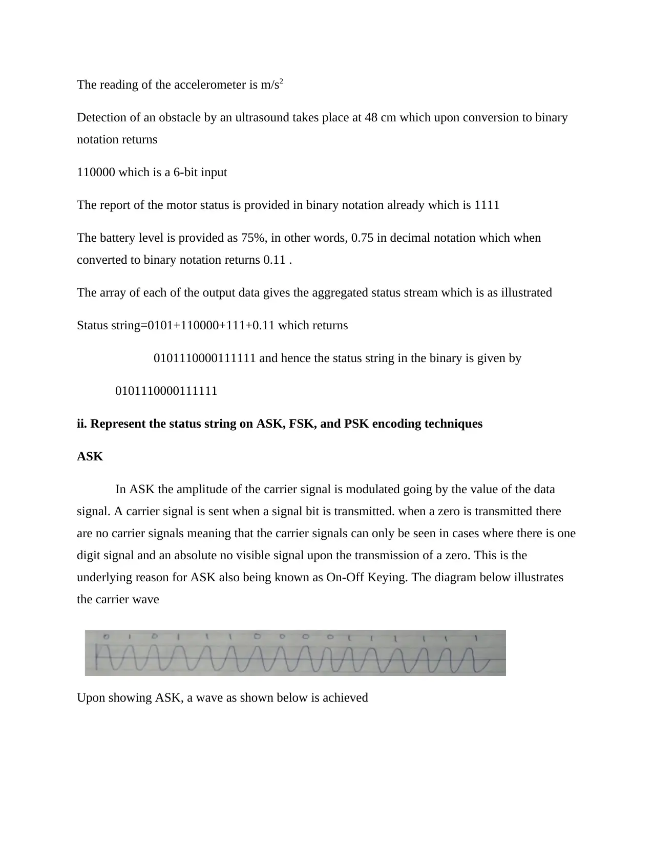
ASK
In ASK the amplitude of the carrier signal is modulated going by the value of the data
signal. A carrier signal is sent when a signal bit is transmitted. when a zero is transmitted there
are no carrier signals meaning that the carrier signals can only be seen in cases where there is one
digit signal and an absolute no visible signal upon the transmission of a zero. This is the
underlying reason for ASK also being known as On-Off Keying. The diagram below illustrates
the carrier wave
Upon showing ASK, a wave as shown below is achieved
Detection of an obstacle by an ultrasound takes place at 48 cm which upon conversion to binary
notation returns
110000 which is a 6-bit input
The report of the motor status is provided in binary notation already which is 1111
The battery level is provided as 75%, in other words, 0.75 in decimal notation which when
converted to binary notation returns 0.11 .
The array of each of the output data gives the aggregated status stream which is as illustrated
Status string=0101+110000+111+0.11 which returns
0101110000111111 and hence the status string in the binary is given by
0101110000111111
ii. Represent the status string on ASK, FSK, and PSK encoding techniques
ASK
In ASK the amplitude of the carrier signal is modulated going by the value of the data
signal. A carrier signal is sent when a signal bit is transmitted. when a zero is transmitted there
are no carrier signals meaning that the carrier signals can only be seen in cases where there is one
digit signal and an absolute no visible signal upon the transmission of a zero. This is the
underlying reason for ASK also being known as On-Off Keying. The diagram below illustrates
the carrier wave
Upon showing ASK, a wave as shown below is achieved
Paraphrase This Document
Need a fresh take? Get an instant paraphrase of this document with our AI Paraphraser
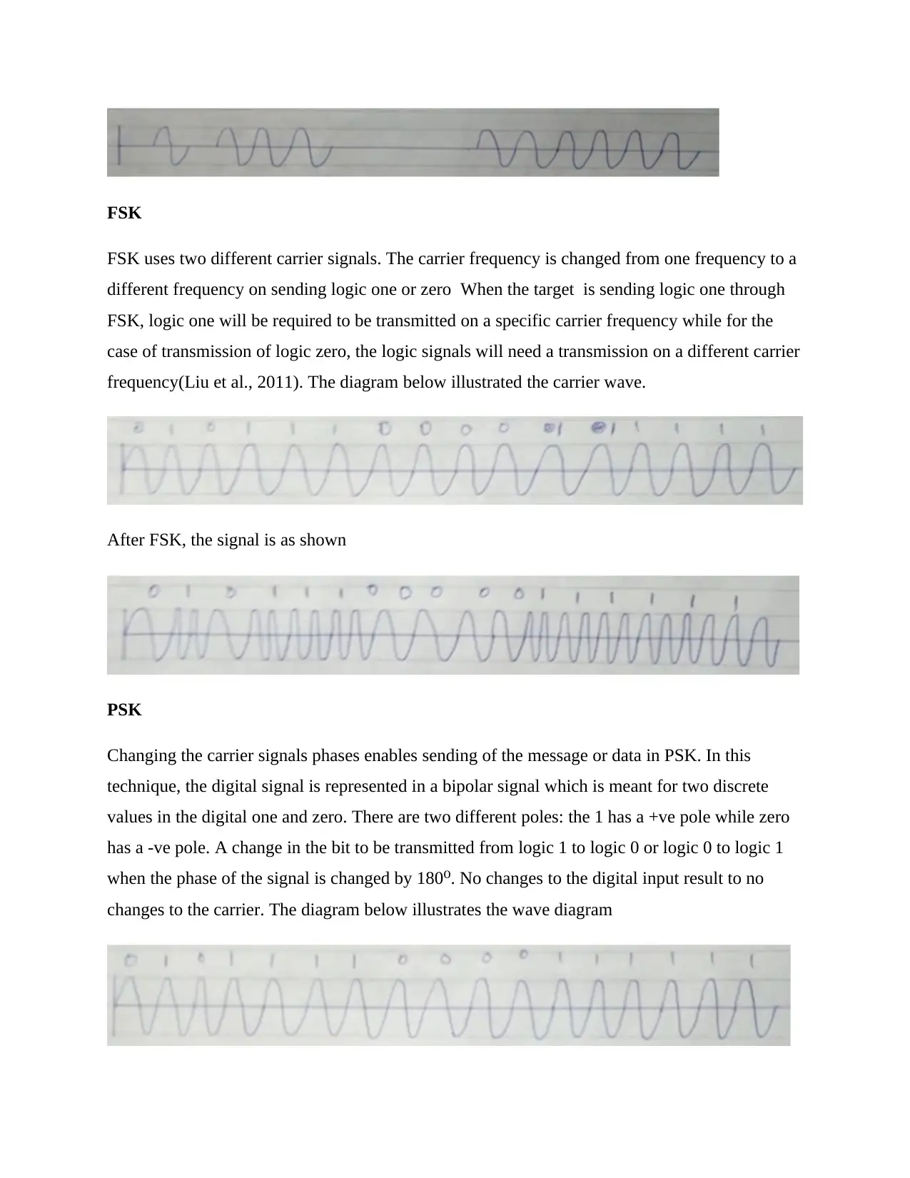
FSK
FSK uses two different carrier signals. The carrier frequency is changed from one frequency to a
different frequency on sending logic one or zero When the target is sending logic one through
FSK, logic one will be required to be transmitted on a specific carrier frequency while for the
case of transmission of logic zero, the logic signals will need a transmission on a different carrier
frequency(Liu et al., 2011). The diagram below illustrated the carrier wave.
After FSK, the signal is as shown
PSK
Changing the carrier signals phases enables sending of the message or data in PSK. In this
technique, the digital signal is represented in a bipolar signal which is meant for two discrete
values in the digital one and zero. There are two different poles: the 1 has a +ve pole while zero
has a -ve pole. A change in the bit to be transmitted from logic 1 to logic 0 or logic 0 to logic 1
when the phase of the signal is changed by 180⁰. No changes to the digital input result to no
changes to the carrier. The diagram below illustrates the wave diagram
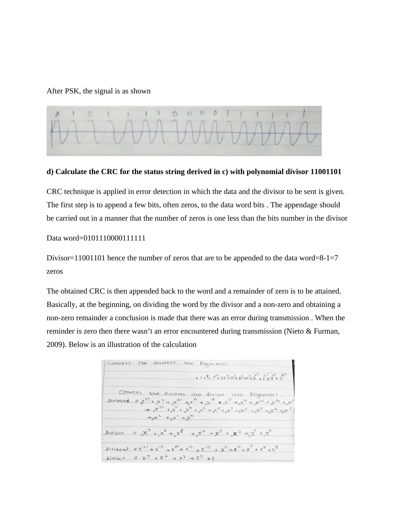
After PSK, the signal is as shown
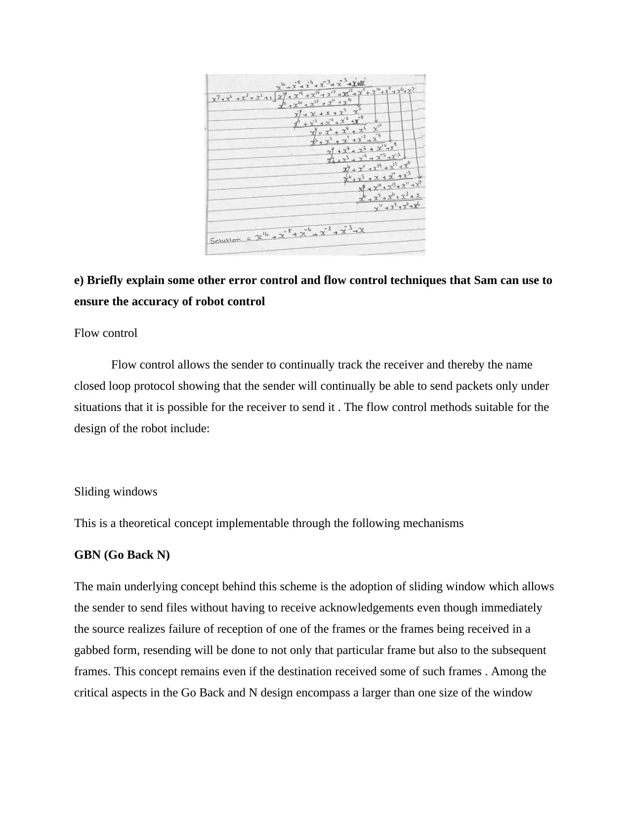
d) Calculate the CRC for the status string derived in c) with polynomial divisor 11001101
CRC technique is applied in error detection in which the data and the divisor to be sent is given.
The first step is to append a few bits, often zeros, to the data word bits . The appendage should
be carried out in a manner that the number of zeros is one less than the bits number in the divisor
Data word=0101110000111111
Divisor=11001101 hence the number of zeros that are to be appended to the data word=8-1=7
zeros
The obtained CRC is then appended back to the word and a remainder of zero is to be attained.
Basically, at the beginning, on dividing the word by the divisor and a non-zero and obtaining a
non-zero remainder a conclusion is made that there was an error during transmission . When the
reminder is zero then there wasn’t an error encountered during transmission (Nieto & Furman,
2009). Below is an illustration of the calculation
⊘ This is a preview!⊘
Do you want full access?
Subscribe today to unlock all pages.
Trusted by 1+ million students worldwide
e) Briefly explain some other error control and flow control techniques that Sam can use to
ensure the accuracy of robot control
Flow control
Flow control allows the sender to continually track the receiver and thereby the name
closed loop protocol showing that the sender will continually be able to send packets only under
situations that it is possible for the receiver to send it . The flow control methods suitable for the
design of the robot include:
Sliding windows
This is a theoretical concept implementable through the following mechanisms
GBN (Go Back N)
The main underlying concept behind this scheme is the adoption of sliding window which allows
the sender to send files without having to receive acknowledgements even though immediately
the source realizes failure of reception of one of the frames or the frames being received in a
gabbed form, resending will be done to not only that particular frame but also to the subsequent
frames. This concept remains even if the destination received some of such frames . Among the
critical aspects in the Go Back and N design encompass a larger than one size of the window
Paraphrase This Document
Need a fresh take? Get an instant paraphrase of this document with our AI Paraphraser
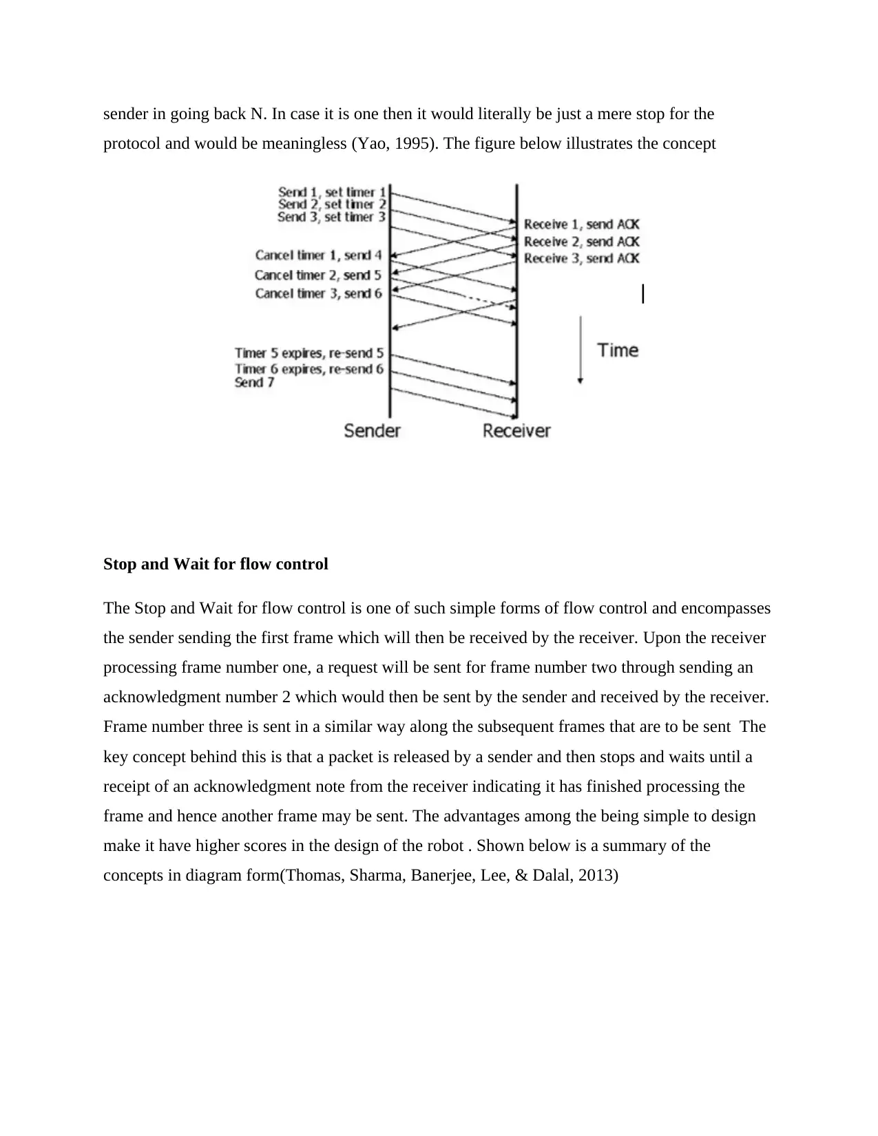
sender in going back N. In case it is one then it would literally be just a mere stop for the
protocol and would be meaningless (Yao, 1995). The figure below illustrates the concept
Stop and Wait for flow control
The Stop and Wait for flow control is one of such simple forms of flow control and encompasses
the sender sending the first frame which will then be received by the receiver. Upon the receiver
processing frame number one, a request will be sent for frame number two through sending an
acknowledgment number 2 which would then be sent by the sender and received by the receiver.
Frame number three is sent in a similar way along the subsequent frames that are to be sent The
key concept behind this is that a packet is released by a sender and then stops and waits until a
receipt of an acknowledgment note from the receiver indicating it has finished processing the
frame and hence another frame may be sent. The advantages among the being simple to design
make it have higher scores in the design of the robot . Shown below is a summary of the
concepts in diagram form(Thomas, Sharma, Banerjee, Lee, & Dalal, 2013)
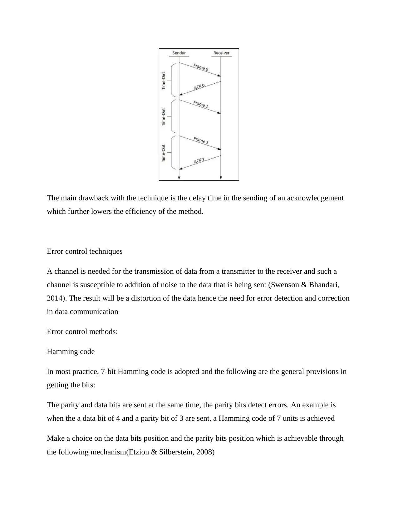
The main drawback with the technique is the delay time in the sending of an acknowledgement
which further lowers the efficiency of the method.
Error control techniques
A channel is needed for the transmission of data from a transmitter to the receiver and such a
channel is susceptible to addition of noise to the data that is being sent (Swenson & Bhandari,
2014). The result will be a distortion of the data hence the need for error detection and correction
in data communication
Error control methods:
Hamming code
In most practice, 7-bit Hamming code is adopted and the following are the general provisions in
getting the bits:
The parity and data bits are sent at the same time, the parity bits detect errors. An example is
when the a data bit of 4 and a parity bit of 3 are sent, a Hamming code of 7 units is achieved
Make a choice on the data bits position and the parity bits position which is achievable through
the following mechanism(Etzion & Silberstein, 2008)
⊘ This is a preview!⊘
Do you want full access?
Subscribe today to unlock all pages.
Trusted by 1+ million students worldwide
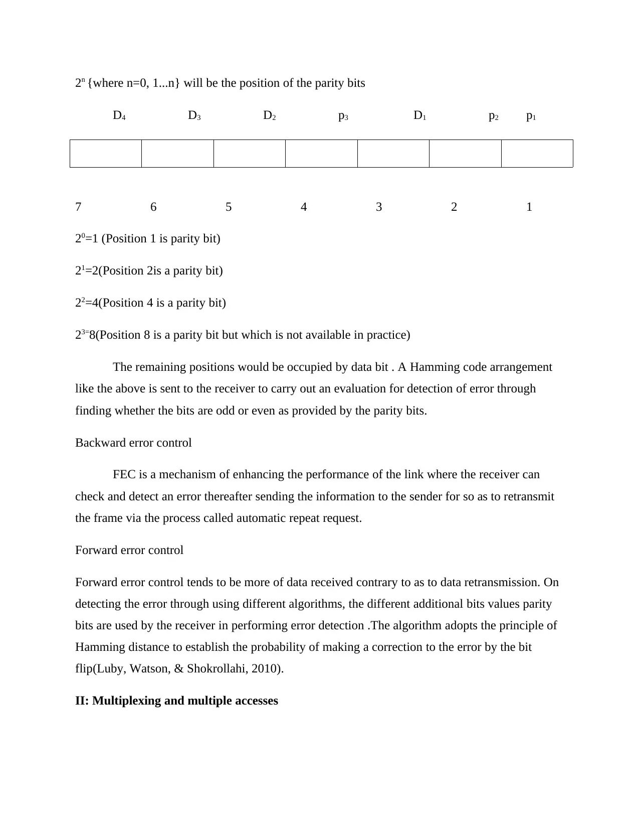
2n {where n=0, 1...n} will be the position of the parity bits
D4 D3 D2 p3 D1 p2 p1
7 6 5 4 3 2 1
20=1 (Position 1 is parity bit)
21=2(Position 2is a parity bit)
22=4(Position 4 is a parity bit)
23=8(Position 8 is a parity bit but which is not available in practice)
The remaining positions would be occupied by data bit . A Hamming code arrangement
like the above is sent to the receiver to carry out an evaluation for detection of error through
finding whether the bits are odd or even as provided by the parity bits.
Backward error control
FEC is a mechanism of enhancing the performance of the link where the receiver can
check and detect an error thereafter sending the information to the sender for so as to retransmit
the frame via the process called automatic repeat request.
Forward error control
Forward error control tends to be more of data received contrary to as to data retransmission. On
detecting the error through using different algorithms, the different additional bits values parity
bits are used by the receiver in performing error detection .The algorithm adopts the principle of
Hamming distance to establish the probability of making a correction to the error by the bit
flip(Luby, Watson, & Shokrollahi, 2010).
II: Multiplexing and multiple accesses
Paraphrase This Document
Need a fresh take? Get an instant paraphrase of this document with our AI Paraphraser
Each radio spectrum has a limited bandwidth which needs to be accessible to all the
subscribers for use. Multiplexing allows abundant mobile users to have access to the narrow
spectrum. Below are the various techniques
a) Explain TDM, FDM and CDMA multiplexing techniques with suitable diagrams
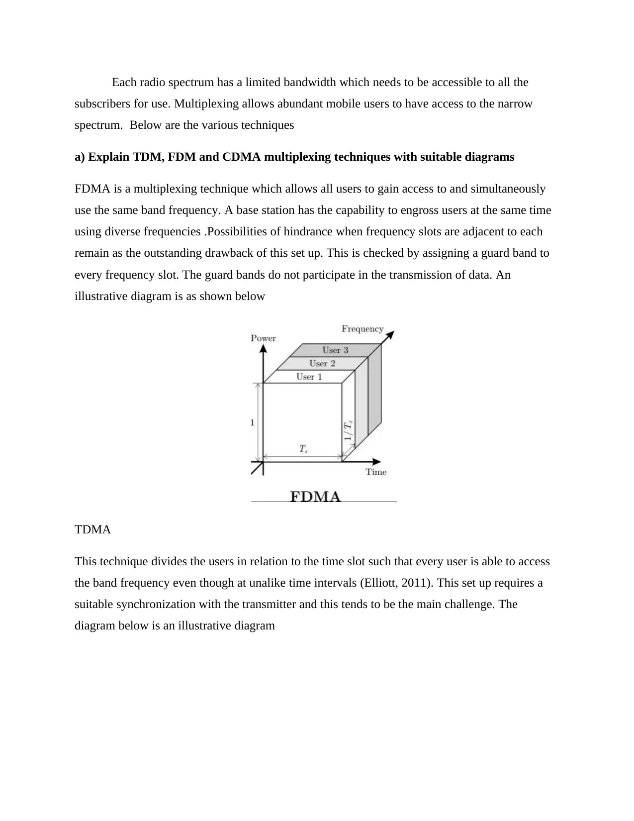
FDMA is a multiplexing technique which allows all users to gain access to and simultaneously
use the same band frequency. A base station has the capability to engross users at the same time
using diverse frequencies .Possibilities of hindrance when frequency slots are adjacent to each
remain as the outstanding drawback of this set up. This is checked by assigning a guard band to
every frequency slot. The guard bands do not participate in the transmission of data. An
illustrative diagram is as shown below
TDMA
This technique divides the users in relation to the time slot such that every user is able to access
the band frequency even though at unalike time intervals (Elliott, 2011). This set up requires a
suitable synchronization with the transmitter and this tends to be the main challenge. The
diagram below is an illustrative diagram
subscribers for use. Multiplexing allows abundant mobile users to have access to the narrow
spectrum. Below are the various techniques
a) Explain TDM, FDM and CDMA multiplexing techniques with suitable diagrams
FDMA is a multiplexing technique which allows all users to gain access to and simultaneously
use the same band frequency. A base station has the capability to engross users at the same time
using diverse frequencies .Possibilities of hindrance when frequency slots are adjacent to each
remain as the outstanding drawback of this set up. This is checked by assigning a guard band to
every frequency slot. The guard bands do not participate in the transmission of data. An
illustrative diagram is as shown below
TDMA
This technique divides the users in relation to the time slot such that every user is able to access
the band frequency even though at unalike time intervals (Elliott, 2011). This set up requires a
suitable synchronization with the transmitter and this tends to be the main challenge. The
diagram below is an illustrative diagram
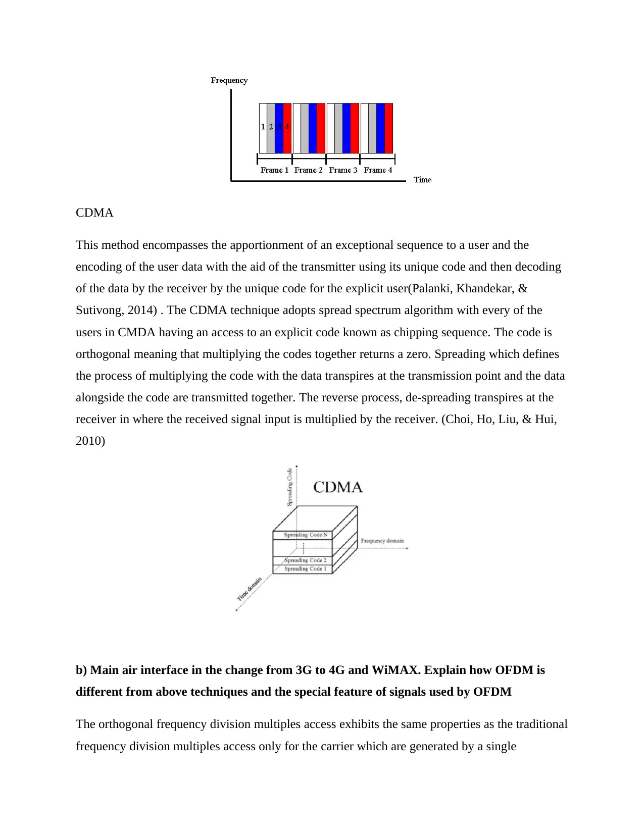
CDMA
This method encompasses the apportionment of an exceptional sequence to a user and the
encoding of the user data with the aid of the transmitter using its unique code and then decoding
of the data by the receiver by the unique code for the explicit user(Palanki, Khandekar, &
Sutivong, 2014) . The CDMA technique adopts spread spectrum algorithm with every of the
users in CMDA having an access to an explicit code known as chipping sequence. The code is
orthogonal meaning that multiplying the codes together returns a zero. Spreading which defines
the process of multiplying the code with the data transpires at the transmission point and the data
alongside the code are transmitted together. The reverse process, de-spreading transpires at the
receiver in where the received signal input is multiplied by the receiver. (Choi, Ho, Liu, & Hui,
2010)
b) Main air interface in the change from 3G to 4G and WiMAX. Explain how OFDM is
different from above techniques and the special feature of signals used by OFDM
The orthogonal frequency division multiples access exhibits the same properties as the traditional
frequency division multiples access only for the carrier which are generated by a single
⊘ This is a preview!⊘
Do you want full access?
Subscribe today to unlock all pages.
Trusted by 1+ million students worldwide
1 out of 17
Related Documents


Your All-in-One AI-Powered Toolkit for Academic Success.
+13062052269
info@desklib.com
Available 24*7 on WhatsApp / Email
![[object Object]](/_next/static/media/star-bottom.7253800d.svg)
Unlock your academic potential
Copyright © 2020–2026 A2Z Services. All Rights Reserved. Developed and managed by ZUCOL.