Designing a High-Speed Wireless Data Link Link Budget Analysis

Verified

Added on  2023/03/30

|4
|399
|218
Practical Assignment
AI Summary
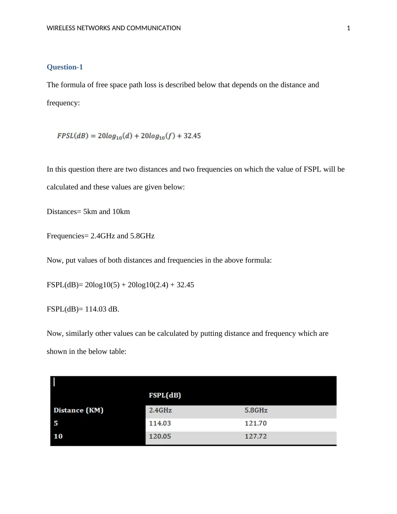
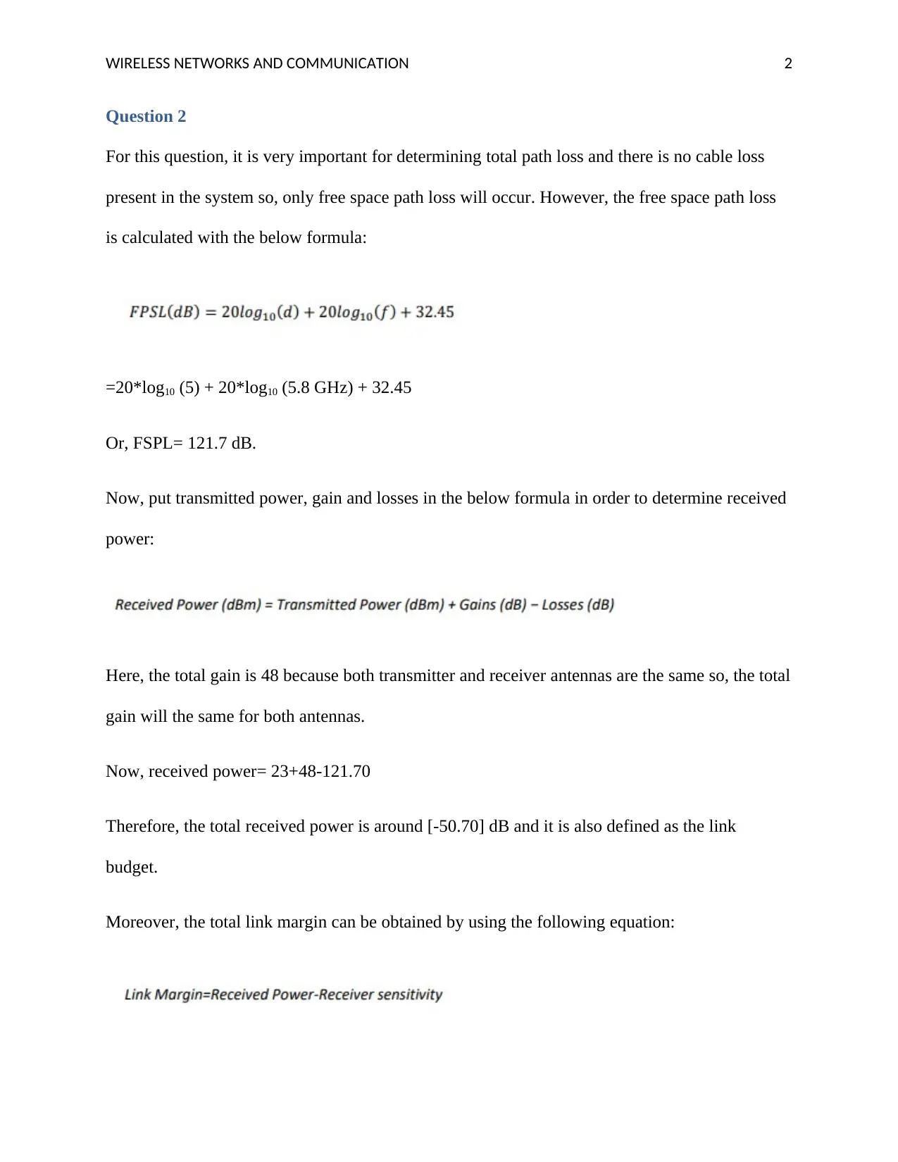
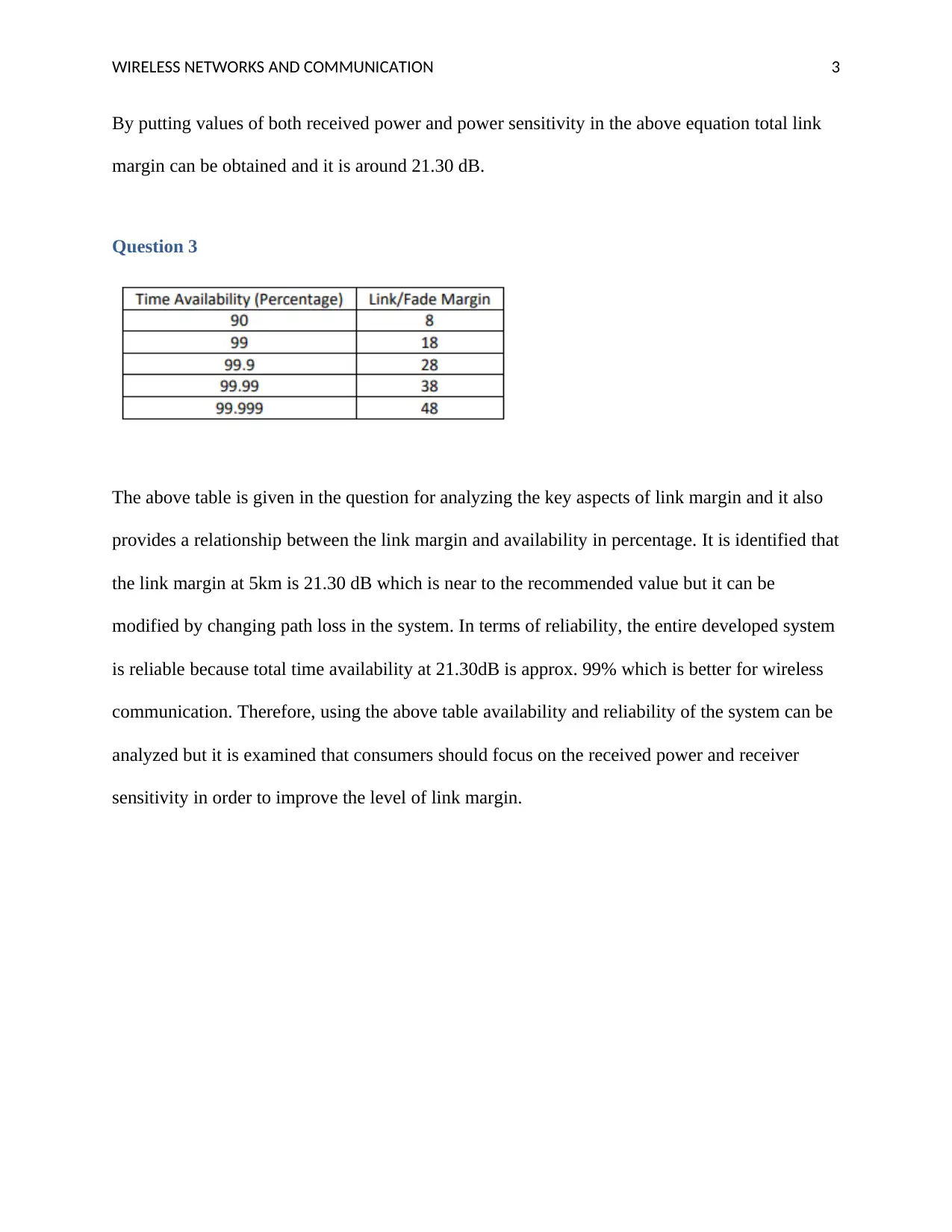
This assignment focuses on the link budget analysis of a high-speed wireless data link. It begins by calculating free space path loss at different distances and frequencies, essential for understanding signal attenuation. The analysis then moves on to determining the total path loss, considering only free space path loss in this scenario, and subsequently calculating the received power by incorporating transmitted power, antenna gains, and losses. The link margin, which indicates the difference between received power and receiver sensitivity, is then computed, providing insights into the system's reliability and performance. Finally, the assignment explores the relationship between link margin and system availability, emphasizing the importance of received power and receiver sensitivity for enhancing link margin levels. The solution provides a detailed breakdown of the calculations and analysis, offering a comprehensive understanding of wireless link budget design and optimization.
Document Page
WIRELESS NETWORKS AND COMMUNICATION 0
Link Budget analysis
tabler-icon-diamond-filled.svg

Paraphrase This Document

Need a fresh take? Get an instant paraphrase of this document with our AI Paraphraser
Document Page
WIRELESS NETWORKS AND COMMUNICATION 1
Question-1
The formula of free space path loss is described below that depends on the distance and
frequency:
In this question there are two distances and two frequencies on which the value of FSPL will be
calculated and these values are given below:
Distances= 5km and 10km
Frequencies= 2.4GHz and 5.8GHz
Now, put values of both distances and frequencies in the above formula:
FSPL(dB)= 20log10(5) + 20log10(2.4) + 32.45
FSPL(dB)= 114.03 dB.
Now, similarly other values can be calculated by putting distance and frequency which are
shown in the below table:
Document Page
WIRELESS NETWORKS AND COMMUNICATION 2
Question 2
For this question, it is very important for determining total path loss and there is no cable loss
present in the system so, only free space path loss will occur. However, the free space path loss
is calculated with the below formula:
=20*log10 (5) + 20*log10 (5.8 GHz) + 32.45
Or, FSPL= 121.7 dB.
Now, put transmitted power, gain and losses in the below formula in order to determine received
power:
Here, the total gain is 48 because both transmitter and receiver antennas are the same so, the total
gain will the same for both antennas.
Now, received power= 23+48-121.70
Therefore, the total received power is around [-50.70] dB and it is also defined as the link
budget.
Moreover, the total link margin can be obtained by using the following equation:
Document Page
WIRELESS NETWORKS AND COMMUNICATION 3
By putting values of both received power and power sensitivity in the above equation total link
margin can be obtained and it is around 21.30 dB.
Question 3
The above table is given in the question for analyzing the key aspects of link margin and it also
provides a relationship between the link margin and availability in percentage. It is identified that
the link margin at 5km is 21.30 dB which is near to the recommended value but it can be
modified by changing path loss in the system. In terms of reliability, the entire developed system
is reliable because total time availability at 21.30dB is approx. 99% which is better for wireless
communication. Therefore, using the above table availability and reliability of the system can be
analyzed but it is examined that consumers should focus on the received power and receiver
sensitivity in order to improve the level of link margin.
chevron_up_icon
1 out of 4
circle_padding
hide_on_mobile
zoom_out_icon
[object Object]