Wireless Networking Concepts: Path Loss and Cellular Design

Verified

Added on  2022/12/21

|5
|710
|41
Homework Assignment
AI Summary
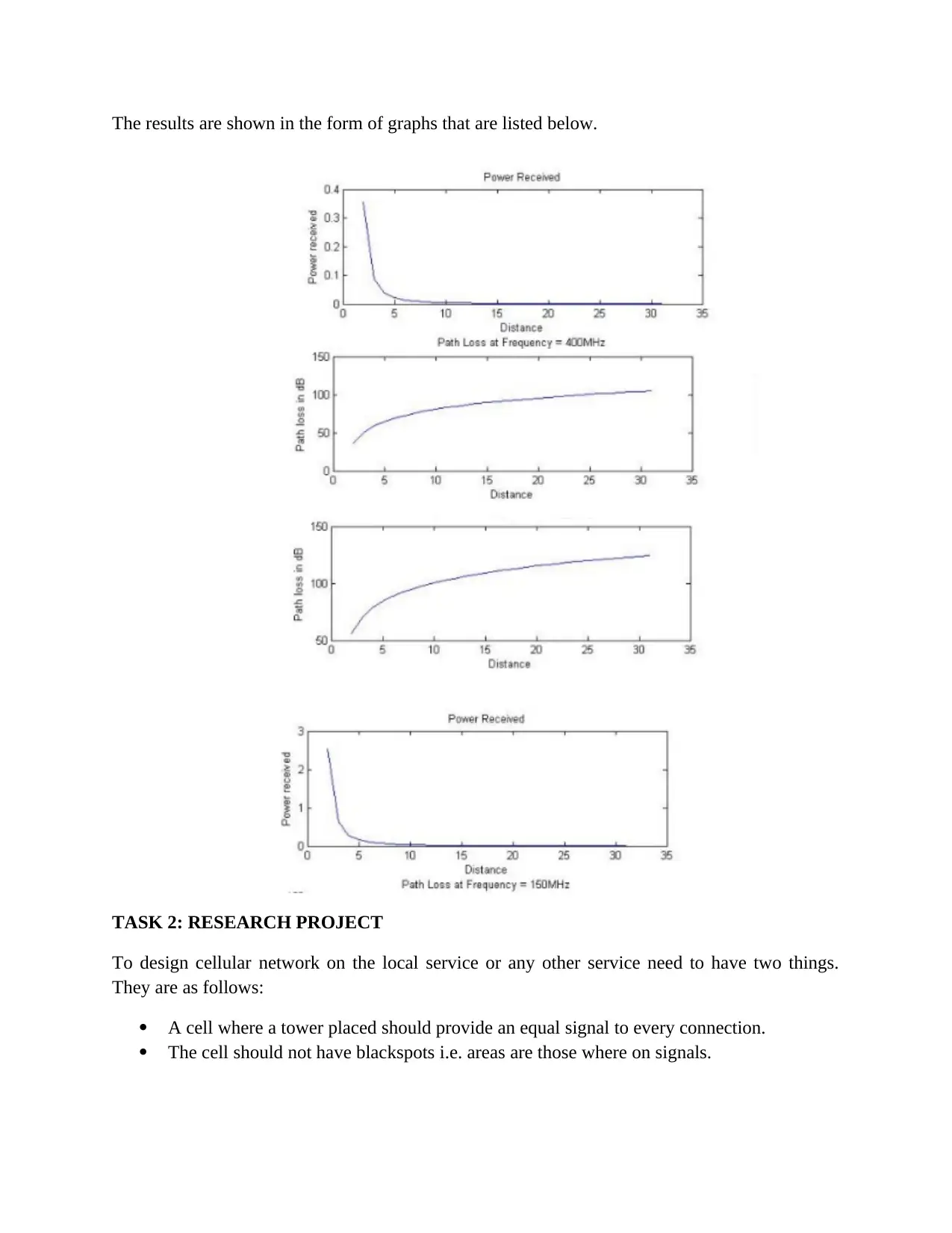
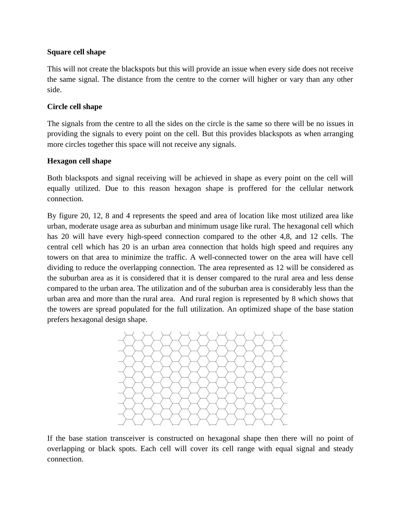
This document presents a solution to a wireless networking assignment, encompassing two primary tasks. The first task focuses on free space propagation and path loss analysis, utilizing MATLAB code to simulate and visualize the relationship between distance and received power, as well as the path loss in dB. The results are displayed graphically, illustrating the decrease in received power and the increase in path loss with distance. The second task delves into the design of cellular networks, exploring different cell shapes (square, circle, and hexagon) and their implications for signal coverage and the avoidance of blackspots. The hexagon cell shape is identified as the optimal choice due to its ability to provide equal signal strength to all connections and minimize blackspots. The document further discusses the application of hexagonal cells in various areas, such as urban, suburban, and rural, and how cell size and network design can be optimized to manage traffic and ensure efficient signal distribution. The solution references existing research on path loss analysis and cellular network design.
Document Page
WIRELESS NETWORKING CONCEPTS
tabler-icon-diamond-filled.svg

Paraphrase This Document

Need a fresh take? Get an instant paraphrase of this document with our AI Paraphraser
Document Page
TASK 1: FREE SPACE PROPOGATION AND PATH LOSS
Transmit power and speed between transmitter and receiver will usually decrease due to the path
loss (represented as the pl_subscript f space (dB)) and the distance of the function is represented
as d.
clc
clear all
close all
pt=100;
gt=1;
gr=1;
c=3*10^8;
f=1000*10^6;
lambda=c/f;
for distance=1:31
pr()distance=(pt*gt*gr)/((4*pi*(distance-1))/lambda)^2;
Pathloss(d)=((4*pi*(distance-1))/lambda)^2;
Pathloss_in_dB(d)=10*log(Pathloss(distance));
end
subplot(211)
plot(pr)
title(‘Power Received’)
xlabel(‘Distance’)
ylable(‘Power received’)
subplot(212)
plot(Pathloss_in_dB)
title(‘Path Loss at Frequency = 1000MHz’)
xlabel(‘Distance’)
ylabel(‘Path loss in dB’)
Document Page
The results are shown in the form of graphs that are listed below.
TASK 2: RESEARCH PROJECT
To design cellular network on the local service or any other service need to have two things.
They are as follows:
A cell where a tower placed should provide an equal signal to every connection.
The cell should not have blackspots i.e. areas are those where on signals.
Document Page
Square cell shape
This will not create the blackspots but this will provide an issue when every side does not receive
the same signal. The distance from the centre to the corner will higher or vary than any other
side.
Circle cell shape
The signals from the centre to all the sides on the circle is the same so there will be no issues in
providing the signals to every point on the cell. But this provides blackspots as when arranging
more circles together this space will not receive any signals.
Hexagon cell shape
Both blackspots and signal receiving will be achieved in shape as every point on the cell will
equally utilized. Due to this reason hexagon shape is proffered for the cellular network
connection.
By figure 20, 12, 8 and 4 represents the speed and area of location like most utilized area like
urban, moderate usage area as suburban and minimum usage like rural. The hexagonal cell which
has 20 will have every high-speed connection compared to the other 4,8, and 12 cells. The
central cell which has 20 is an urban area connection that holds high speed and requires any
towers on that area to minimize the traffic. A well-connected tower on the area will have cell
dividing to reduce the overlapping connection. The area represented as 12 will be considered as
the suburban area as it is considered that it is denser compared to the rural area and less dense
compared to the urban area. The utilization and of the suburban area is considerably less than the
urban area and more than the rural area. And rural region is represented by 8 which shows that
the towers are spread populated for the full utilization. An optimized shape of the base station
prefers hexagonal design shape.
If the base station transceiver is constructed on hexagonal shape then there will no point of
overlapping or black spots. Each cell will cover its cell range with equal signal and steady
connection.
tabler-icon-diamond-filled.svg

Paraphrase This Document

Need a fresh take? Get an instant paraphrase of this document with our AI Paraphraser
Document Page
REFERENCES
Rakesh, N., & Srivatsa, S. K. (2013). A study on path loss analysis for gsm Mobile networks for
urban, rural and Suburban regions of Karnataka state. International Journal of
Distributed and Parallel Systems, 4(1), 53.
Anish, N. Neelima & A. Deepti , G. (2015). An optimized cellular network design using various
technologies within a service area. International Journal of Engineering Research and
General Science. 3(2).
chevron_up_icon
1 out of 5
circle_padding
hide_on_mobile
zoom_out_icon
[object Object]