Wireless Networks and Communication - Fall Semester Assignment
VerifiedAdded on 2023/01/23
|14
|2720
|49
Homework Assignment
AI Summary
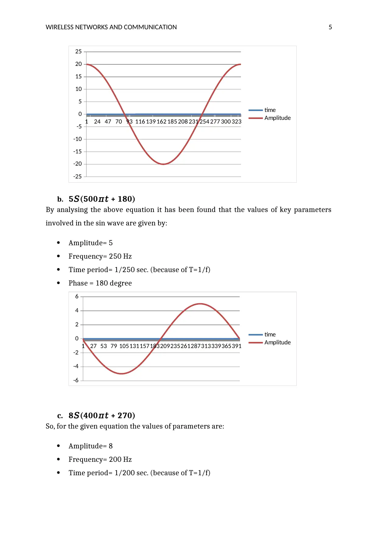
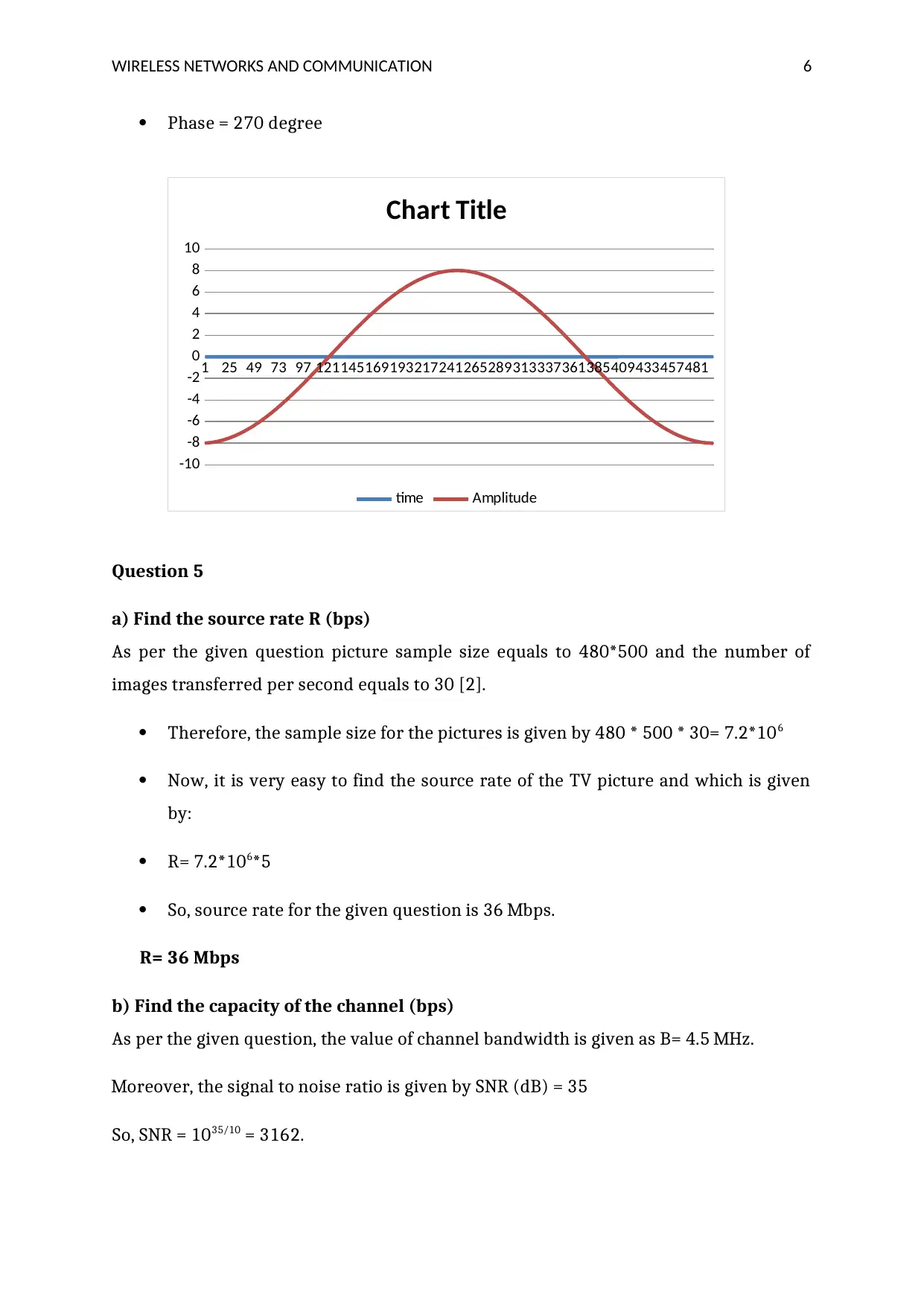
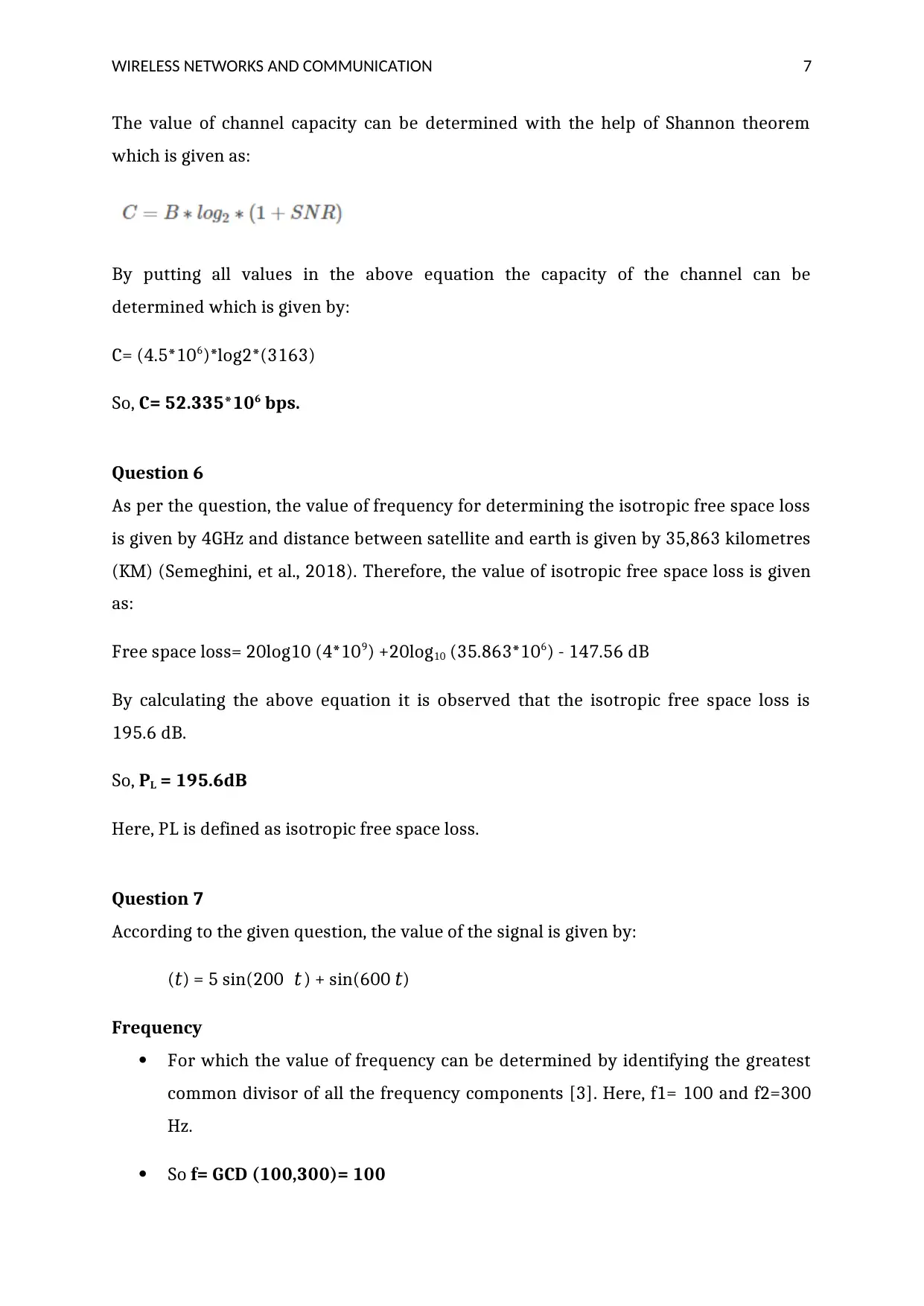
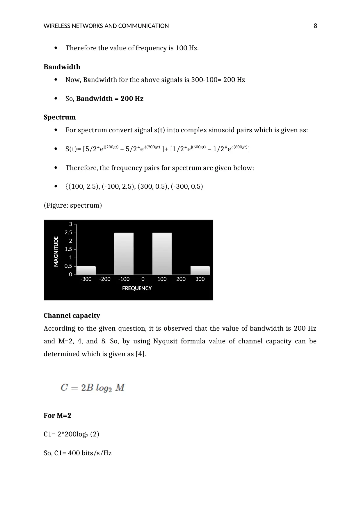
This document provides a detailed solution to a wireless networks and communication assignment. The solution addresses several key concepts, including analyzing signal characteristics like amplitude, frequency, time period, and phase for various waveforms. It also covers the application of layer models to describe real-world scenarios such as pizza ordering and diplomatic communication. The assignment further explores the calculation of channel capacity using the Shannon theorem and investigates the differences between circuit switching and packet switching. Additionally, it includes problems related to isotropic free space loss and antenna height calculations for effective line-of-sight communication. The document also covers the Nyquist theorem and its application in increasing data rates. The student has provided detailed answers to all the questions in the assignment brief.

Wireless networks and Communication
Paraphrase This Document
Need a fresh take? Get an instant paraphrase of this document with our AI Paraphraser

WIRELESS NETWORKS AND COMMUNICATION 1
Question 1
In this question the guest recommends the pizza menu, the host provides the pizza
blackboard to the customer and guest selects the specific pizza in order to place an
order. After analysing the given figure it is observed that the order of ordering process
will be given by Gusts-> (customer request the crowd to have pizza) Host -> (the host
utilizes mobile phone ordering purpose) Telephone -> (mobile phone used to transfer
information from customer to the shop kipper) Telephone -> Order clerk -> (The order
clerk transfer the consumer instruction to the pizza chef) Pizza cook. The guest places
an order with the cock and the host transfer the information of the customer to clerk
regarding their order. Moreover, the cock provides the pizza to the worker with the
instruction form and the clerk pack the pizza and pass to the delivery address. It is
analysed that the road provides the physical path for the delivery and delivery boy to
deliver the order to the customer effectively.
Question 2
In the first case PM have English interpreters on their employees or staffs. Below figure
indicates hypothetical telephone communication between French PM and Chinese PM.

WIRELESS NETWORKS AND COMMUNICATION 2
As per the above figure both French and Chinese PMs express as if they are talking to
one another directly. For instance, when the Prime Minister of French speaks anything
then he addresses his remarks directly to the Prime Minister of China. It is observed
that the message or information is transferred to other Prime Minister by using the
telephonic system and the Prime Minister of French use translator system in order to
translate his remarks into English and telephone this message to the Prime Minister of
China which also used a translator system that translates this information into the
Chinese language. Therefore, translators play a major role in decoding the transferred
signals or information from one Primer Minister to another. Both Prime Ministers use
translators to convert messages into English, French and Chinese language.
Question 3
For the above waveform, the value of amplitude, frequency, time period and phase are
given by:
Amplitude = 15
Frequency = 1/3 Hz
Time period = 3 sec.
⊘ This is a preview!⊘
Do you want full access?
Subscribe today to unlock all pages.

Trusted by 1+ million students worldwide

WIRELESS NETWORKS AND COMMUNICATION 3
Phase = 0 degree
For the above waveform values are given below:
Amplitude= 4
Time period= 6.5 sec.
Frequency= 1/6.5 Hz
Phase = 0 degree
For the above waveform the values of parameters are given by:
Amplitude=7.8 (approx.)
Time period= 2.3 sec
Frequency= 1/2.3 Hz
Phase= 90 degree
Phase = 0 degree
For the above waveform values are given below:
Amplitude= 4
Time period= 6.5 sec.
Frequency= 1/6.5 Hz
Phase = 0 degree
For the above waveform the values of parameters are given by:
Amplitude=7.8 (approx.)
Time period= 2.3 sec
Frequency= 1/2.3 Hz
Phase= 90 degree
Paraphrase This Document
Need a fresh take? Get an instant paraphrase of this document with our AI Paraphraser

WIRELESS NETWORKS AND COMMUNICATION 4
Question 4
a. 10𝑆(2𝜋(100)𝑡)
Amplitude= 10
Frequency= 100 Hz
Time period= 1/100 sec. (1/f)
Phase = 0 degree
1 7 13 19 25 31 37 43 49 55 61 67 73 79 85 91 97
-15
-10
-5
0
5
10
15
time
Amplitude
a. 20𝑆(2𝜋(30)𝑡 + 90)
After analysing the above equation it has found that the values of waveform’s
parameters are determined by comparing with the standard sin wave which is given as:
X= a sin (2pift+phase) [1].
So,
Amplitude= 20
Frequency= 30 Hz
Time period= 1/30 sec. (because T=1/f)
Phase = 90 degree

WIRELESS NETWORKS AND COMMUNICATION 5
1 24 47 70 93 116 139 162 185 208 231 254 277 300 323
-25
-20
-15
-10
-5
0
5
10
15
20
25
time
Amplitude
b. 5𝑆(500𝜋𝑡 + 180)
By analysing the above equation it has been found that the values of key parameters
involved in the sin wave are given by:
Amplitude= 5
Frequency= 250 Hz
Time period= 1/250 sec. (because of T=1/f)
Phase = 180 degree
1 27 53 79 105131157183209235261287313339365391
-6
-4
-2
0
2
4
6
time
Amplitude
c. 8𝑆(400𝜋𝑡 + 270)
So, for the given equation the values of parameters are:
Amplitude= 8
Frequency= 200 Hz
Time period= 1/200 sec. (because of T=1/f)
⊘ This is a preview!⊘
Do you want full access?
Subscribe today to unlock all pages.

Trusted by 1+ million students worldwide

WIRELESS NETWORKS AND COMMUNICATION 6
Phase = 270 degree
1 25 49 73 97 121145169193217241265289313337361385409433457481
-10
-8
-6
-4
-2
0
2
4
6
8
10
Chart Title
time Amplitude
Question 5
a) Find the source rate R (bps)
As per the given question picture sample size equals to 480*500 and the number of
images transferred per second equals to 30 [2].
Therefore, the sample size for the pictures is given by 480 * 500 * 30= 7.2*106
Now, it is very easy to find the source rate of the TV picture and which is given
by:
R= 7.2*106*5
So, source rate for the given question is 36 Mbps.
R= 36 Mbps
b) Find the capacity of the channel (bps)
As per the given question, the value of channel bandwidth is given as B= 4.5 MHz.
Moreover, the signal to noise ratio is given by SNR (dB) = 35
So, SNR = 1035/10 = 3162.
Paraphrase This Document
Need a fresh take? Get an instant paraphrase of this document with our AI Paraphraser

WIRELESS NETWORKS AND COMMUNICATION 7
The value of channel capacity can be determined with the help of Shannon theorem
which is given as:
By putting all values in the above equation the capacity of the channel can be
determined which is given by:
C= (4.5*106)*log2*(3163)
So, C= 52.335*106 bps.
Question 6
As per the question, the value of frequency for determining the isotropic free space loss
is given by 4GHz and distance between satellite and earth is given by 35,863 kilometres
(KM) (Semeghini, et al., 2018). Therefore, the value of isotropic free space loss is given
as:
Free space loss= 20log10 (4*109) +20log10 (35.863*106) - 147.56 dB
By calculating the above equation it is observed that the isotropic free space loss is
195.6 dB.
So, PL = 195.6dB
Here, PL is defined as isotropic free space loss.
Question 7
According to the given question, the value of the signal is given by:
(𝑡) = 5 sin(200𝜋 𝑡 ) + sin(600𝜋𝑡)
Frequency
For which the value of frequency can be determined by identifying the greatest
common divisor of all the frequency components [3]. Here, f1= 100 and f2=300
Hz.
So f= GCD (100,300)= 100

WIRELESS NETWORKS AND COMMUNICATION 8
Therefore the value of frequency is 100 Hz.
Bandwidth
Now, Bandwidth for the above signals is 300-100= 200 Hz
So, Bandwidth = 200 Hz
Spectrum
For spectrum convert signal s(t) into complex sinusoid pairs which is given as:
S(t)= [5/2*ej(200t) – 5/2*e-j(200t) ]+ [1/2*ej(600t) – 1/2*e-j(600t)]
Therefore, the frequency pairs for spectrum are given below:
{(100, 2.5), (-100, 2.5), (300, 0.5), (-300, 0.5)
(Figure: spectrum)
-300 -200 -100 0 100 200 300
0
0.5
1
1.5
2
2.5
3
FREQUENCY
MAGNITUDE
Channel capacity
According to the given question, it is observed that the value of bandwidth is 200 Hz
and M=2, 4, and 8. So, by using Nyqusit formula value of channel capacity can be
determined which is given as [4].
For M=2
C1= 2*200log2 (2)
So, C1= 400 bits/s/Hz
⊘ This is a preview!⊘
Do you want full access?
Subscribe today to unlock all pages.

Trusted by 1+ million students worldwide

WIRELESS NETWORKS AND COMMUNICATION 9
For M=4
C2= 2*200log2 (4)
C2= 800 bits/s/Hz
For M=8
C3= 2*200log2 (8)
C3= 1200 bits/s/Hz
Question 8
According to the Nyquist theorem, the value of data is dependent on major three factors,
for example, the bandwidth, numbers of levels used in the digital information and the
overall quality of the channel of the level of noise [5]. It is observed that there are major
two formulas used for finding the value of data rates such as Nyquist formula and
Shannon formula. For this question, the Nyquist theorem can be applied in order to
identify another way for increasing the data rate over a channel [6]. There are two
processes by which the value of data rate can be increased for example by increasing
the value of bandwidth and increasing the numbers of signal levels [7].
According to Nyquist theorem the value of bit rate can be determined by the
following formula:
Bit Rate = 2*Bandwidth * log2 (L)
Here, L is defined as the level of applied signals.
So, for the given question, the data rate can be enhanced by growing the value of signal
levels because the data rate is directly co-related to the number of signal levels. The
main disadvantage of improving signals levels is that consumers may decrease the
overall reliability and flexibility of the system. Moreover, it can impact on the overall
performance of the system due to which consumer can receive errors and distortion in
the signals or information.
Paraphrase This Document
Need a fresh take? Get an instant paraphrase of this document with our AI Paraphraser

WIRELESS NETWORKS AND COMMUNICATION 10
Question 9
Circuit switching and packet switching
Packet switching is very different from circuit switching because it does not require
developing a channel for the system. In the case of packet switching long information
are divided into numbers of packets but in circuit switching consumer can transfer long
message easily [8]. The major difference between circuit switching and packet
switching is that the circuit switching needs a physical path between source and
destination in order to exchange information but packet switching does not need any
bodily path.
In circuit switching all data packets utilize the same path for communication but in the
case of packet switching every packet travel independently and need different packets.
Moreover, packet switching does not reserve any bandwidth for future communication
but circuit switching reserve the complete bandwidth in advance in order to send and
receive data [9]. It is analysed that the circuit switching a waste large amount of
bandwidth during communication process but packet switching does not waste
bandwidth. The packet switching systems also support the forward and store
transmission but circuit switching do not store and forward transmission.
Circuit switching Packet Switching
The physical path between source and
destination
No physical path
Reserve the entire bandwidth in advance Does not reserve
Bandwidth wastage No bandwidth wastage
No store and forward transmission Supports store and forward transmission
Data or information is processed at the
source only
Information is processed at all nodes
involving source system
More reliable Less reliable
The main benefit of packet switching process over circuit switching is it does not waste
bandwidth rather than circuit system. In the case of packet switching data is transferred
directly from source to destination without using any physical path. The other benefit of

WIRELESS NETWORKS AND COMMUNICATION 11
pack switching over circuit switching is that it is more efficient for sharing data packets
form one location to another.
Question 10
As per the given question, the value of the distance between two antennae is d= 40km
and the height of one antenna is twice of the other antenna that means h1=2h2. For
finding the appropriate heights of each antenna in order to produce an effective LOS
communication below formula can be used:
D= 3.57*sqrt (kH1+kH2)
Here, d= 40 km, and Assume k= 1.3
H1= 2H2
By putting all these values in the above formula heights of the antenna can be
determined and which is given by:
40= 3.57*1.1547(sqrt(3H2))
After solving the above equation it has been found that the value of H2 is 31.69 meters
and H1 is 63.38 meters.
So, the height of one antenna is 31.69 meters and height of another antenna is 63.38
meters.
⊘ This is a preview!⊘
Do you want full access?
Subscribe today to unlock all pages.

Trusted by 1+ million students worldwide
1 out of 14
Related Documents
Your All-in-One AI-Powered Toolkit for Academic Success.
+13062052269
info@desklib.com
Available 24*7 on WhatsApp / Email
Unlock your academic potential
Copyright © 2020–2025 A2Z Services. All Rights Reserved. Developed and managed by ZUCOL.


