MITS4004 Research: ICMP Protocol Analysis Using Wireshark

Verified

Added on  2023/04/21

|17
|2228
|389
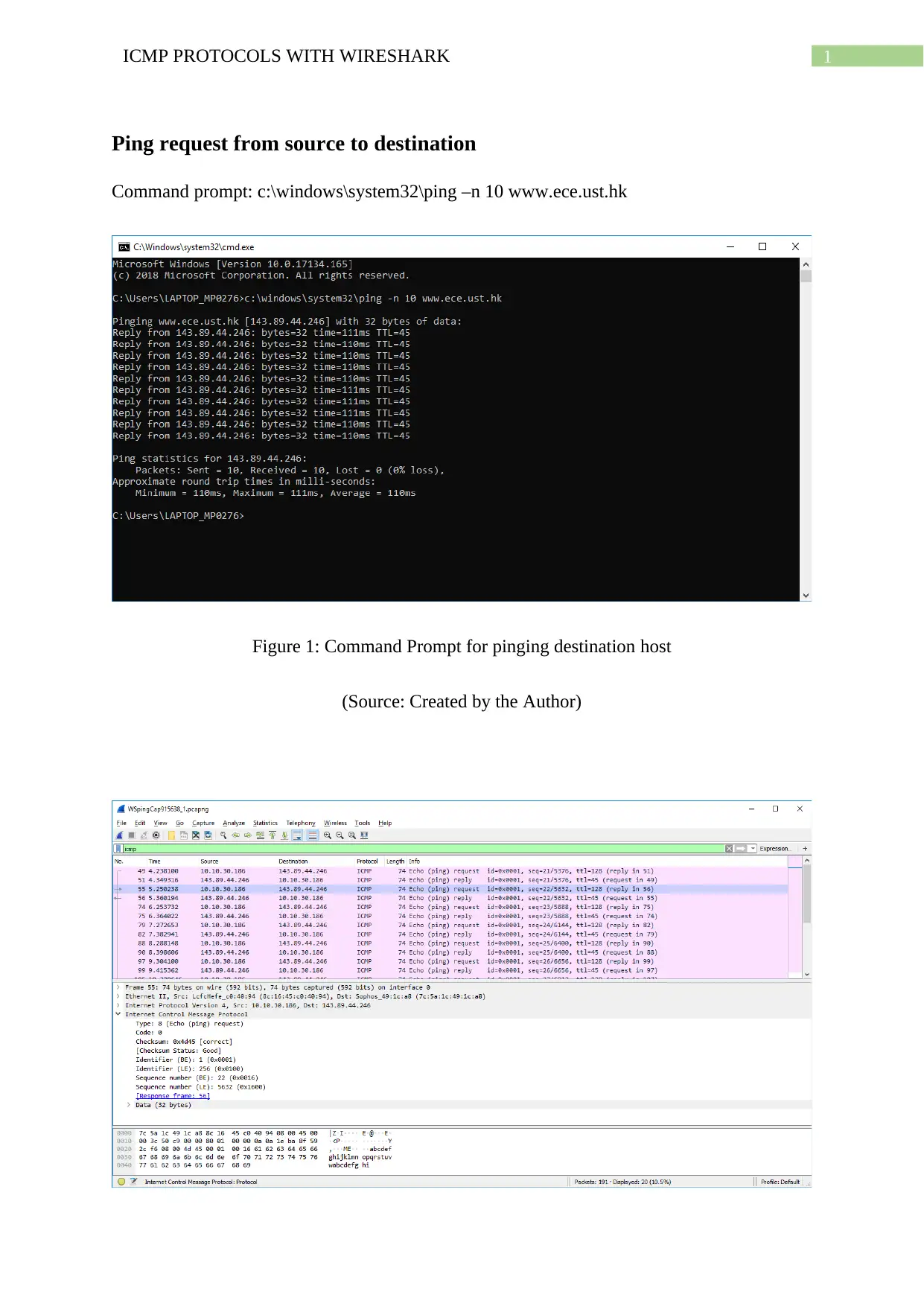
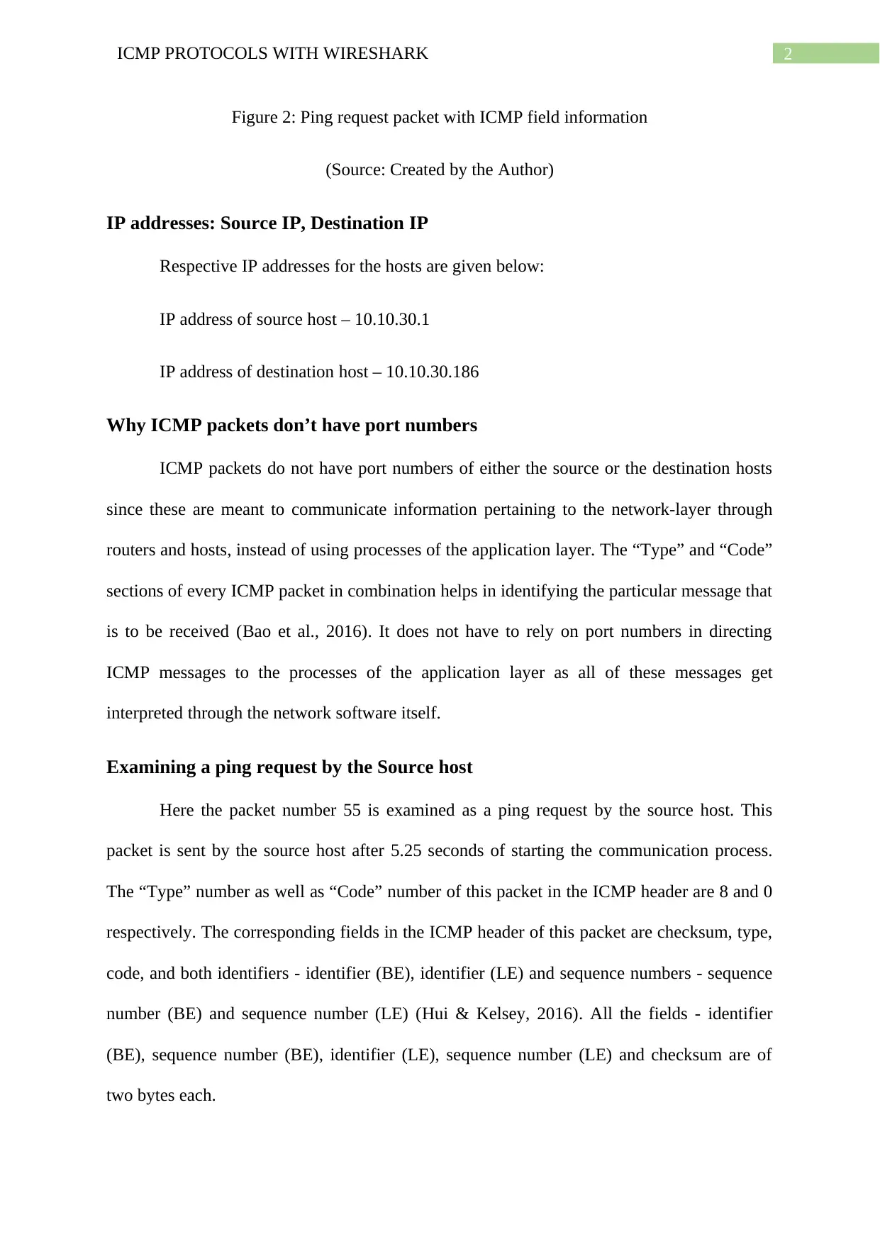
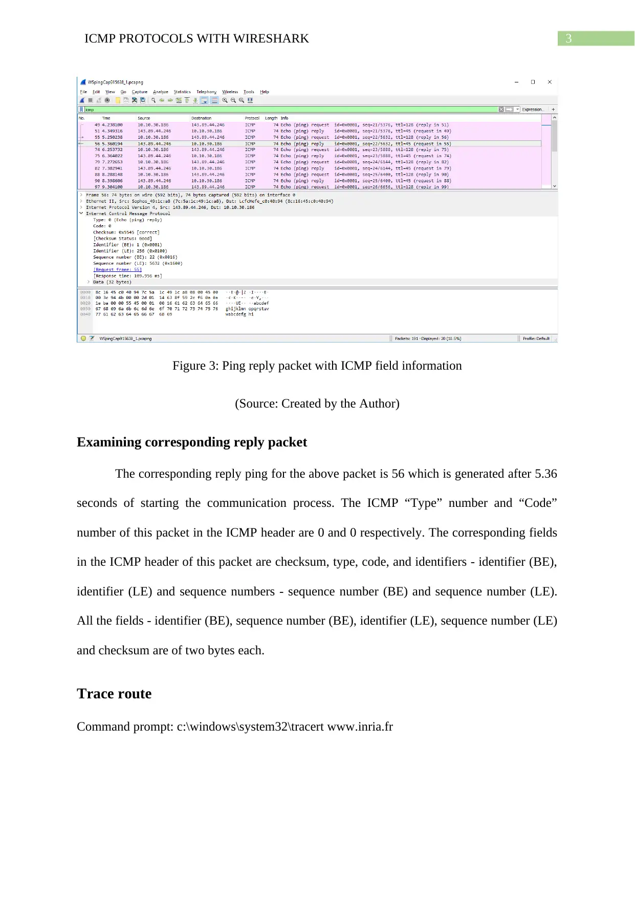
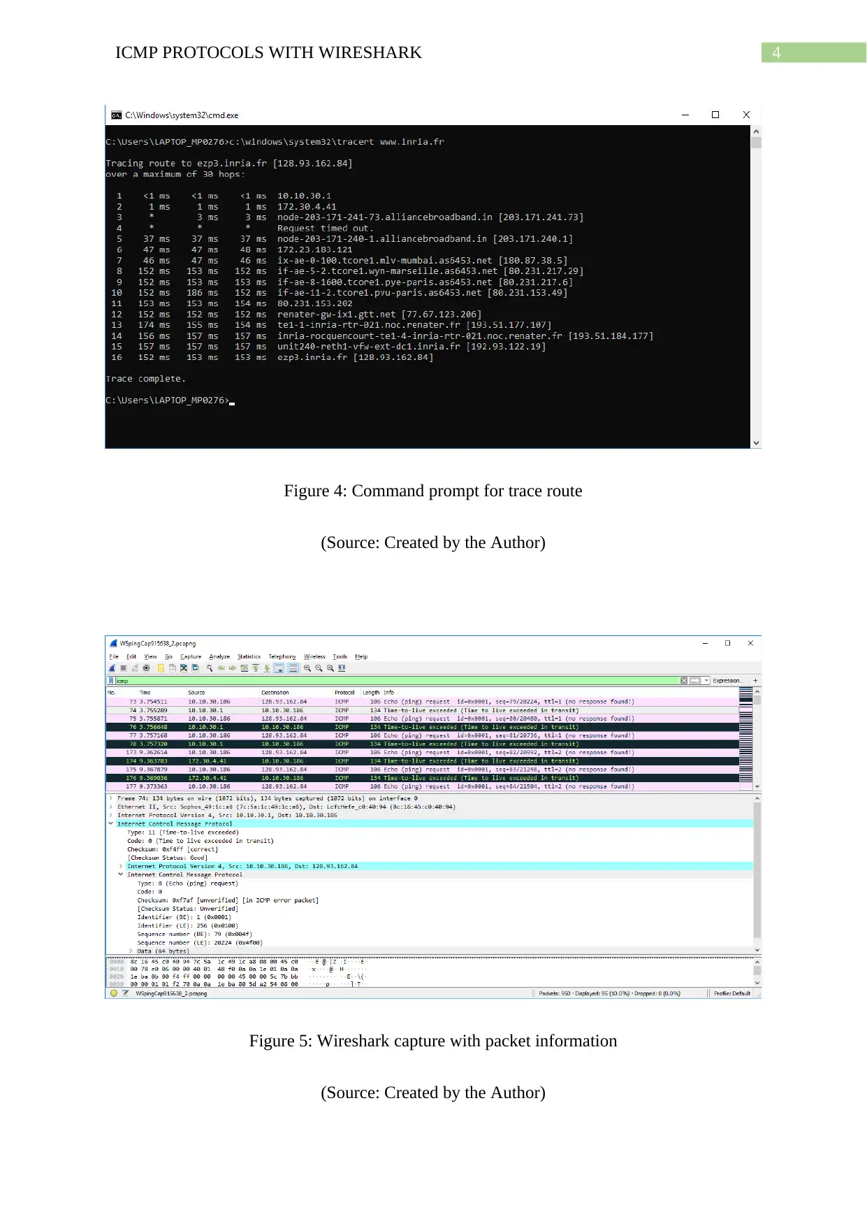
Practical Assignment
AI Summary
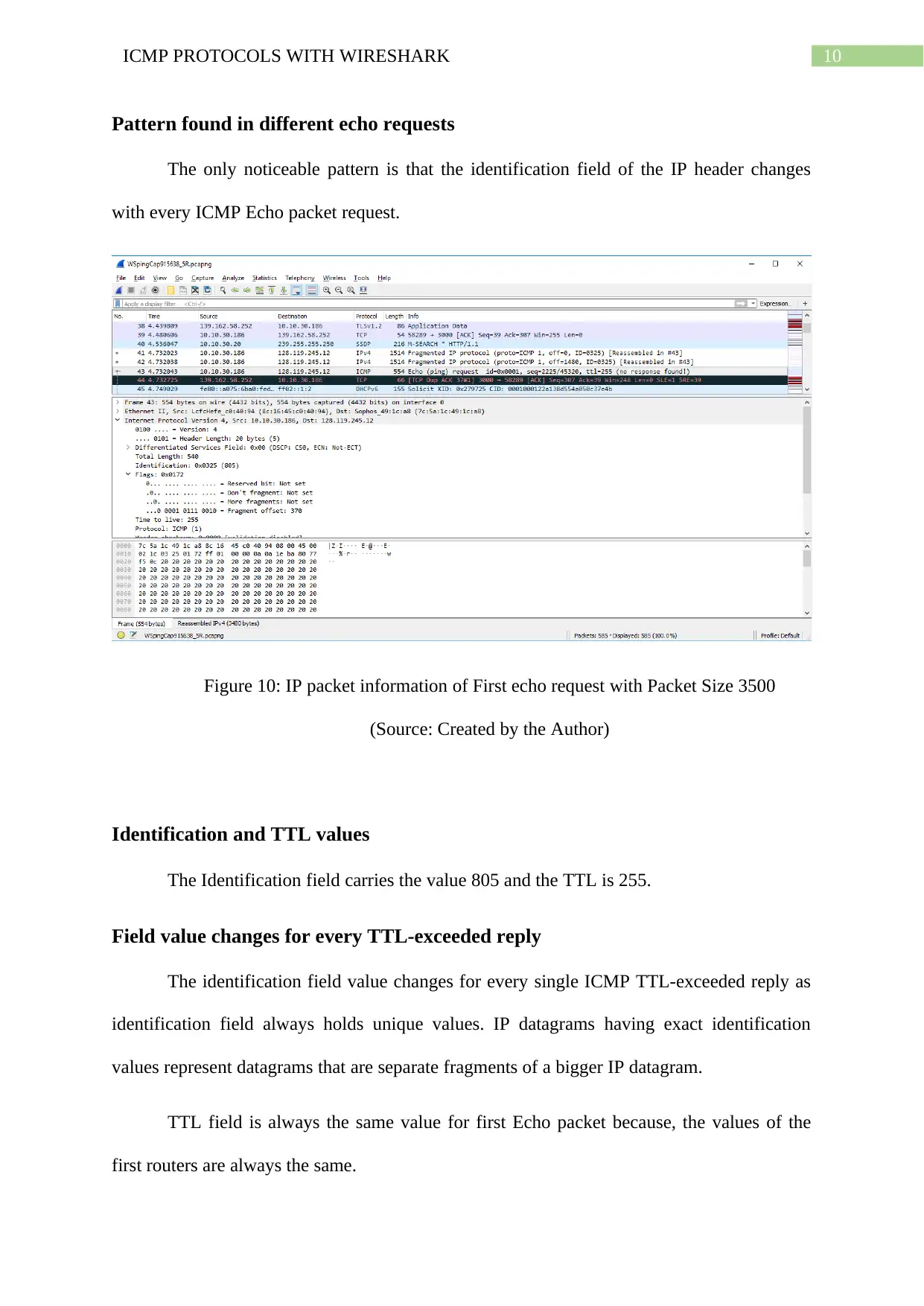
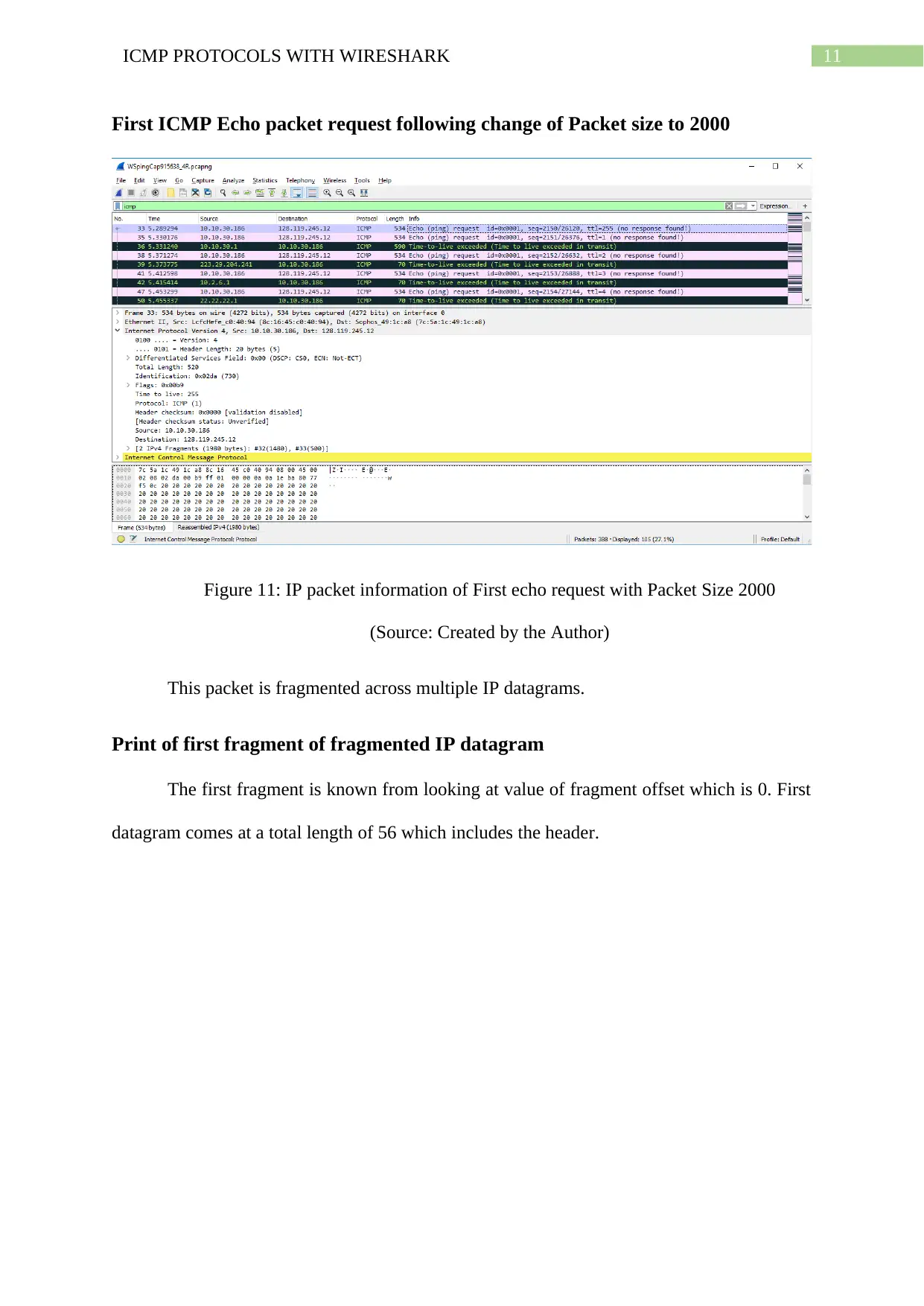
This assignment provides a comprehensive analysis of ICMP (Internet Control Message Protocol) using Wireshark, focusing on practical aspects such as ping requests and trace routes. It examines the structure and function of ICMP packets, including type and code fields, and contrasts ICMP echo packets with ICMP error packets. The analysis includes capturing and interpreting Wireshark data related to ping requests, ping replies, and trace route commands, identifying IP addresses, and analyzing packet contents. Key observations include identifying links with the longest delays in trace routes, examining IP datagrams, and detailing fields that change or remain constant during ICMP communications. The assignment further explores IP datagram fragmentation, analyzing how packet size affects fragmentation and identifying fields that change between fragments. The document includes screenshots of Wireshark captures to support the analysis and provide visual evidence of the findings. This practical approach offers a detailed understanding of ICMP operations and network behavior.
Document Page
RUNNING HEAD: ICMP PROTOCOLS WITH WIRESHARK
ICMP Protocols with Wireshark
Name of the Student
Name of the University
Author Note
tabler-icon-diamond-filled.svg

Paraphrase This Document

Need a fresh take? Get an instant paraphrase of this document with our AI Paraphraser
Document Page
1ICMP PROTOCOLS WITH WIRESHARK
Ping request from source to destination
Command prompt: c:\windows\system32\ping –n 10 www.ece.ust.hk
Figure 1: Command Prompt for pinging destination host
(Source: Created by the Author)
Document Page
2ICMP PROTOCOLS WITH WIRESHARK
Figure 2: Ping request packet with ICMP field information
(Source: Created by the Author)
IP addresses: Source IP, Destination IP
Respective IP addresses for the hosts are given below:
IP address of source host – 10.10.30.1
IP address of destination host – 10.10.30.186
Why ICMP packets don’t have port numbers
ICMP packets do not have port numbers of either the source or the destination hosts
since these are meant to communicate information pertaining to the network-layer through
routers and hosts, instead of using processes of the application layer. The “Type” and “Code”
sections of every ICMP packet in combination helps in identifying the particular message that
is to be received (Bao et al., 2016). It does not have to rely on port numbers in directing
ICMP messages to the processes of the application layer as all of these messages get
interpreted through the network software itself.
Examining a ping request by the Source host
Here the packet number 55 is examined as a ping request by the source host. This
packet is sent by the source host after 5.25 seconds of starting the communication process.
The “Type” number as well as “Code” number of this packet in the ICMP header are 8 and 0
respectively. The corresponding fields in the ICMP header of this packet are checksum, type,
code, and both identifiers - identifier (BE), identifier (LE) and sequence numbers - sequence
number (BE) and sequence number (LE) (Hui & Kelsey, 2016). All the fields - identifier
(BE), sequence number (BE), identifier (LE), sequence number (LE) and checksum are of
two bytes each.
Document Page
3ICMP PROTOCOLS WITH WIRESHARK
Figure 3: Ping reply packet with ICMP field information
(Source: Created by the Author)
Examining corresponding reply packet
The corresponding reply ping for the above packet is 56 which is generated after 5.36
seconds of starting the communication process. The ICMP “Type” number and “Code”
number of this packet in the ICMP header are 0 and 0 respectively. The corresponding fields
in the ICMP header of this packet are checksum, type, code, and identifiers - identifier (BE),
identifier (LE) and sequence numbers - sequence number (BE) and sequence number (LE).
All the fields - identifier (BE), sequence number (BE), identifier (LE), sequence number (LE)
and checksum are of two bytes each.
Trace route
Command prompt: c:\windows\system32\tracert www.inria.fr
tabler-icon-diamond-filled.svg

Paraphrase This Document

Need a fresh take? Get an instant paraphrase of this document with our AI Paraphraser
Document Page
4ICMP PROTOCOLS WITH WIRESHARK
Figure 4: Command prompt for trace route
(Source: Created by the Author)
Figure 5: Wireshark capture with packet information
(Source: Created by the Author)
Document Page
5ICMP PROTOCOLS WITH WIRESHARK
IP addresses: Source IP, Destination IP
Respective IP addresses for the hosts are given below:
IP address of source host – 10.10.30.186
IP address of destination host – 128.93.162.84
IP protocol number UDP packets are sent by ICMP
If instead UDP packets are sent by ICMP, the IP protocol number for probe packets is
0x11.
Figure 6: ICMP echo packet contents
(Source: Created by the Author)
Examining of ICMP echo packet and the difference from ICMP ping packets
An ICMP echo packet comprise of the exact fields that can be found in a ping query
packet.
Document Page
6ICMP PROTOCOLS WITH WIRESHARK
Figure 7: ICMP error packet contents
(Source: Created by the Author)
Examining of the ICMP error packet and its contents
ICMP error packets are different from any of the query packets while pinging. They
comprise of both the IP headers as also the beginning 8 of the total bytes of the ICMP packet
for which this error occurred.
Examining of the last three digits of ICMP and their difference from error
packets
Last three packets of ICMP are of message type 0 which are echo reply instead of 11
that are TTL expired. These are separate messages as their datagrams show to have reached
the host of the destination prior to the expiry of TTL.
tabler-icon-diamond-filled.svg

Paraphrase This Document

Need a fresh take? Get an instant paraphrase of this document with our AI Paraphraser
Document Page
7ICMP PROTOCOLS WITH WIRESHARK
Trace route link with longest delay and location of the two routers
A link exists between steps 7 and 8 having substantially long delay. This two routers
are located between Asia and Europe among cities Mumbai, (India) and Marseille, (France).
Here, the ping jumps from sub-50 milliseconds to over 150 milliseconds.
IP protocol and tracing IP datagrams
Figure 8: IP datagram
(Source: Created by the Author)
Document Page
8ICMP PROTOCOLS WITH WIRESHARK
Figure 9: IP packet information for trace 1
(Source: Created by the Author)
IP Address – source computer
The source computer’s IP address is 10.10.30.186
Upper layer protocol (IP header) Value
Value of upper layer protocol in IP header is ICMP (1)
Bytes of IP header and IP Datagram Payload
The IP header part consists of 20 bytes while, total length of the packet is 56. Hence
payload of the IP datagram is of (56 - 20) = 36 bytes
Fragmentation in IP Datagram
Value of more fragments – Not Set
Fragment offset – 0
This means data is not fragmented yet.
Document Page
9ICMP PROTOCOLS WITH WIRESHARK
Fields in IP Datagram that always change
IP datagram fields which are always changing – time to live (TTL), identification and
header checksum.
Fields staying constant, Fields which must be constant, Fields which must change
The fields which are staying constant in the IP datagram are:
Version – IPV4
Length of the header
Upper layer Protocol number
Source IP
Destination IP
Differentiated Services.
Fields which should be staying constant are:
Version – IPV4
Header length
Upper layer Protocol number
Source IP
Destination IP
Differentiated Services
Fields which are changing always are:
Identification
Time to live
Header checksum
tabler-icon-diamond-filled.svg

Paraphrase This Document

Need a fresh take? Get an instant paraphrase of this document with our AI Paraphraser
Document Page
10ICMP PROTOCOLS WITH WIRESHARK
Pattern found in different echo requests
The only noticeable pattern is that the identification field of the IP header changes
with every ICMP Echo packet request.
Figure 10: IP packet information of First echo request with Packet Size 3500
(Source: Created by the Author)
Identification and TTL values
The Identification field carries the value 805 and the TTL is 255.
Field value changes for every TTL-exceeded reply
The identification field value changes for every single ICMP TTL-exceeded reply as
identification field always holds unique values. IP datagrams having exact identification
values represent datagrams that are separate fragments of a bigger IP datagram.
TTL field is always the same value for first Echo packet because, the values of the
first routers are always the same.
Document Page
11ICMP PROTOCOLS WITH WIRESHARK
First ICMP Echo packet request following change of Packet size to 2000
Figure 11: IP packet information of First echo request with Packet Size 2000
(Source: Created by the Author)
This packet is fragmented across multiple IP datagrams.
Print of first fragment of fragmented IP datagram
The first fragment is known from looking at value of fragment offset which is 0. First
datagram comes at a total length of 56 which includes the header.
chevron_up_icon
1 out of 17
circle_padding
hide_on_mobile
zoom_out_icon
[object Object]