Multi-Storey Car Park Design Project: Wolverhampton Stadium
VerifiedAdded on 2022/09/28
|12
|1047
|43
Project
AI Summary
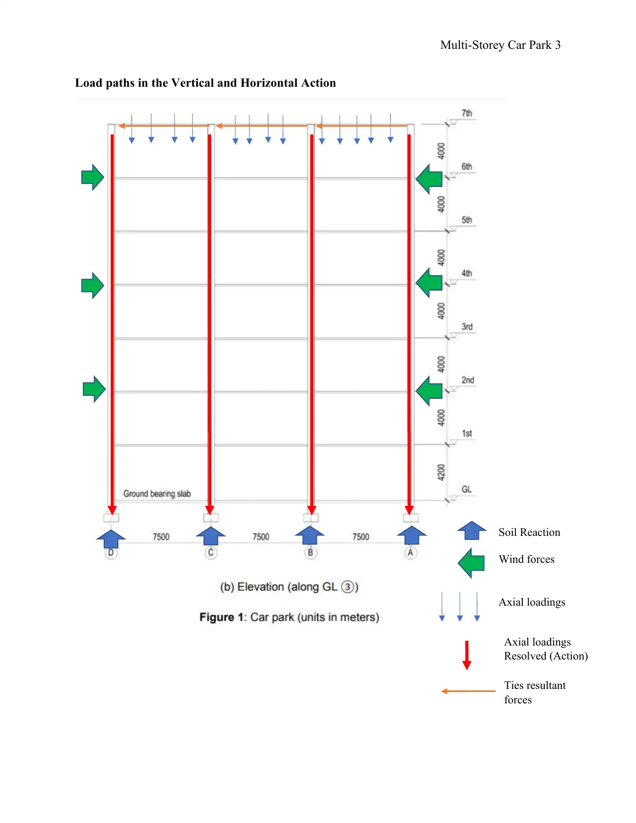
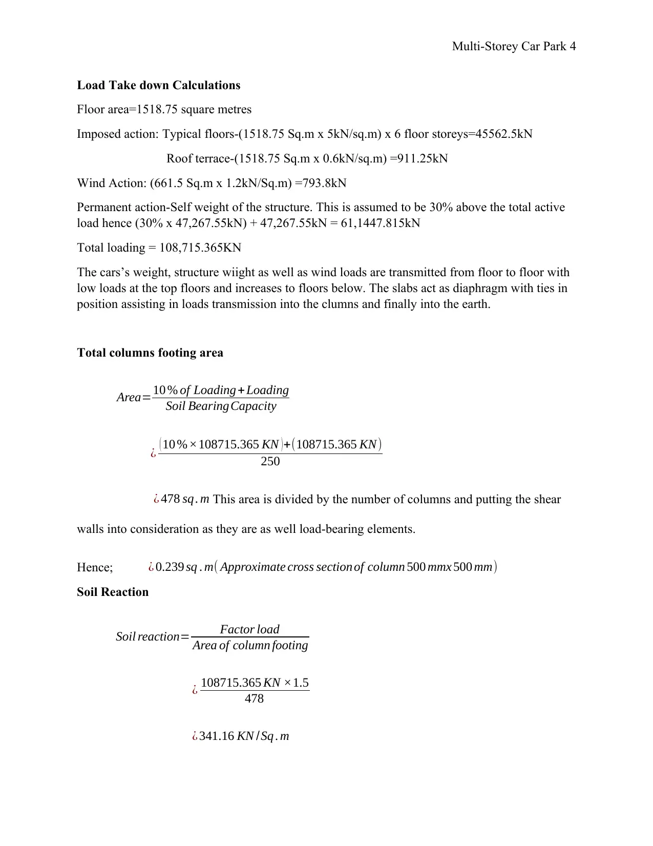
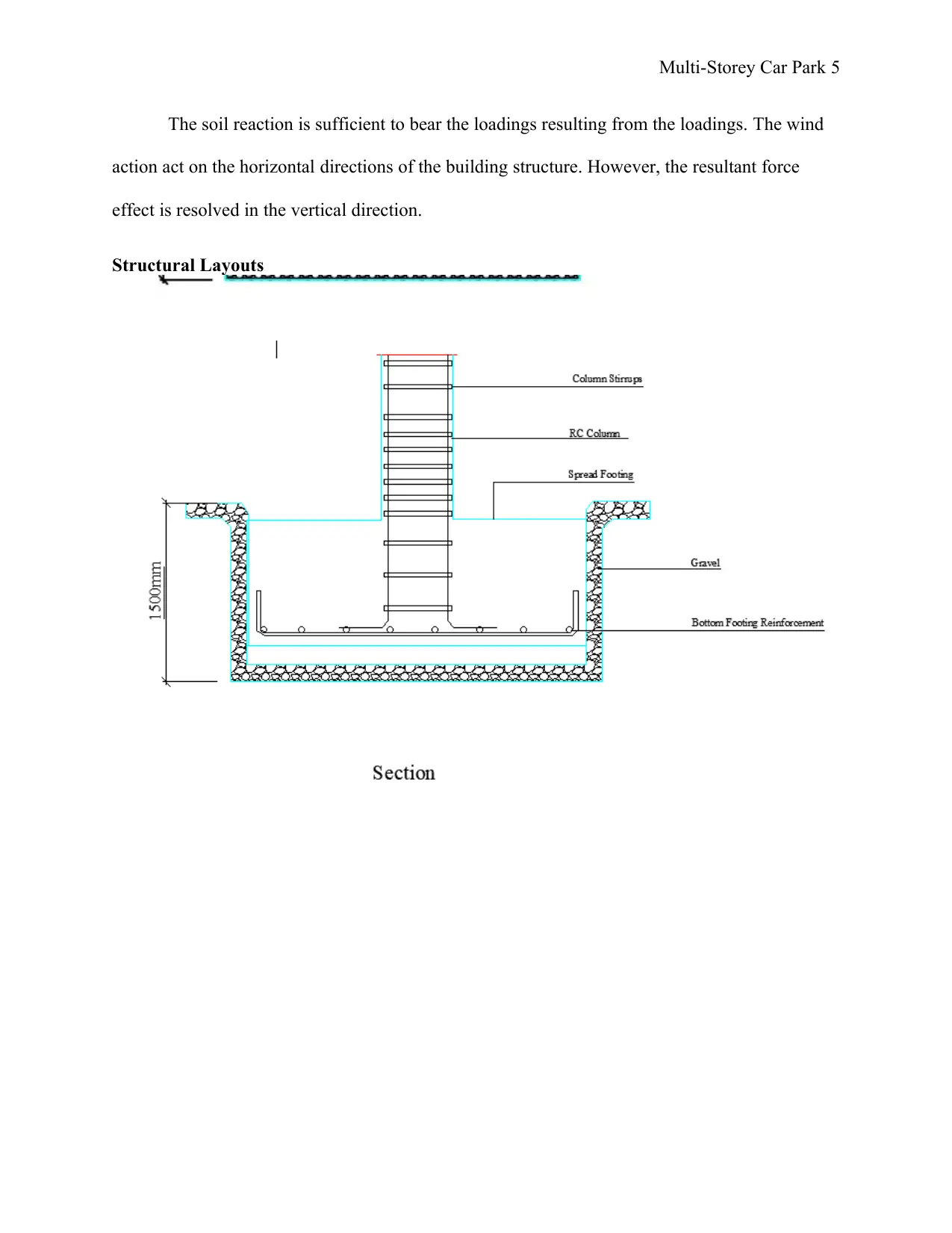
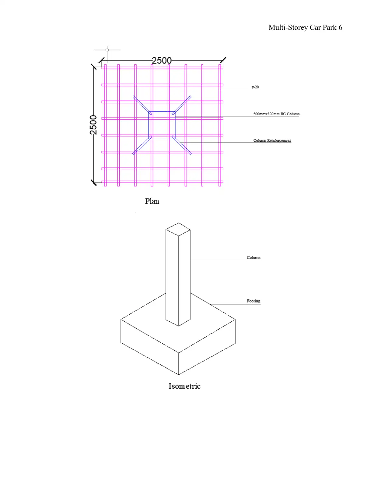
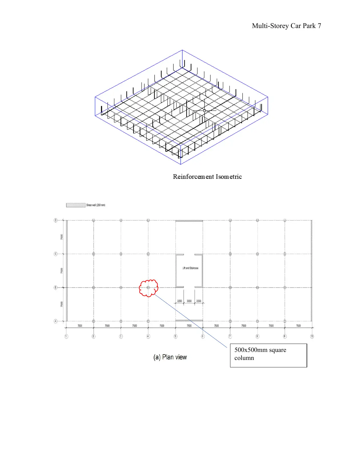
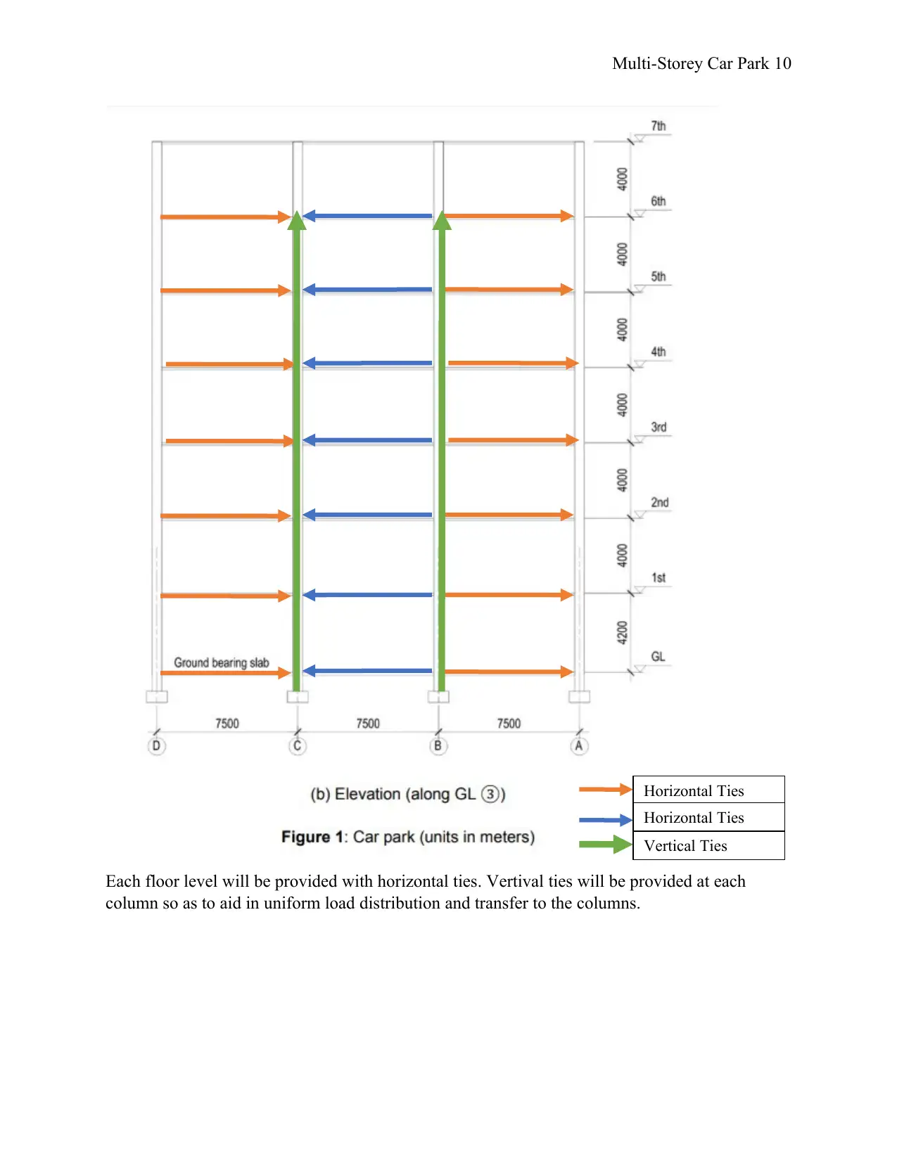
This assignment presents a detailed design project for a six-storey multi-storey car park proposed for the Wolverhampton Molineux Stadium. The project focuses on ensuring the structural stability of the car park, considering both vertical and horizontal loads, including wind effects. The solution includes a site analysis, geological considerations, and adherence to British and European standards, as well as the Building Regulations 2000. The load path calculations, structural layouts, and overall stability checks are presented, along with a discussion of structural robustness and the use of vertical and horizontal ties to enhance the building's integrity. The project emphasizes the importance of shear walls and column design in load distribution and ensuring the car park meets safety standards and robustness requirements, offering a practical application of civil engineering principles.

Multi-Storey Car Park 1
MULTI-STOREY CAR PARK DESIGN PROJECT
Student’s Name
Course
Professor’s Name
Institutional Affiliation
City
Date
MULTI-STOREY CAR PARK DESIGN PROJECT
Student’s Name
Course
Professor’s Name
Institutional Affiliation
City
Date
Paraphrase This Document
Need a fresh take? Get an instant paraphrase of this document with our AI Paraphraser

Multi-Storey Car Park 2
Project Information
The objective of this assignment is to establish whether the stability of a multi-storey
carpark has been put in to account to cater for loadings as well as wind effects exposed on the
structure. The car park is proposed to be erected at the Wolverhampton Molineux Stadium. This
will maximize the available parking area as less ground area is utilized. The car park is to be six
storey with each floor having an area of 1518.75 square metres.
The design has been done as per the British and European Standards as well as the
Building Regulations 2000.
The site-wide information available at the design stage is that the area has an underlying
clay and sandstone. From the hydrology and geological survey of the site, the underlying clay is
stiff and it is consistent. The water table is way below 5 metres from the ground level. The
column footings are expected to be up to 2 metres below the ground level. At this level, the soil
has a bearing capacity of approximately 250KN/ Sq. metres (Buckland 2018)

Multi-Storey Car Park 3
Load paths in the Vertical and Horizontal Action
Soil Reaction
Wind forces
Axial loadings
Axial loadings
Resolved (Action)
Ties resultant
forces
Load paths in the Vertical and Horizontal Action
Soil Reaction
Wind forces
Axial loadings
Axial loadings
Resolved (Action)
Ties resultant
forces
⊘ This is a preview!⊘
Do you want full access?
Subscribe today to unlock all pages.

Trusted by 1+ million students worldwide

Multi-Storey Car Park 4
Load Take down Calculations
Floor area=1518.75 square metres
Imposed action: Typical floors-(1518.75 Sq.m x 5kN/sq.m) x 6 floor storeys=45562.5kN
Roof terrace-(1518.75 Sq.m x 0.6kN/sq.m) =911.25kN
Wind Action: (661.5 Sq.m x 1.2kN/Sq.m) =793.8kN
Permanent action-Self weight of the structure. This is assumed to be 30% above the total active
load hence (30% x 47,267.55kN) + 47,267.55kN = 61,1447.815kN
Total loading = 108,715.365KN
The cars’s weight, structure wiight as well as wind loads are transmitted from floor to floor with
low loads at the top floors and increases to floors below. The slabs act as diaphragm with ties in
position assisting in loads transmission into the clumns and finally into the earth.
Total columns footing area
Area=10 % of Loading + Loading
Soil BearingCapacity
¿ ( 10 %×108715.365 KN ) +(108715.365 KN)
250
¿ 478 sq . m This area is divided by the number of columns and putting the shear
walls into consideration as they are as well load-bearing elements.
Hence; ¿ 0.239 sq . m( Approximate cross section of column 500 mmx 500 mm)
Soil Reaction
Soil reaction= Factor load
Area of column footing
¿ 108715.365 KN ×1.5
478
¿ 341.16 KN /Sq . m
Paraphrase This Document
Need a fresh take? Get an instant paraphrase of this document with our AI Paraphraser

Multi-Storey Car Park 5
The soil reaction is sufficient to bear the loadings resulting from the loadings. The wind
action act on the horizontal directions of the building structure. However, the resultant force
effect is resolved in the vertical direction.
Structural Layouts
The soil reaction is sufficient to bear the loadings resulting from the loadings. The wind
action act on the horizontal directions of the building structure. However, the resultant force
effect is resolved in the vertical direction.
Structural Layouts

Multi-Storey Car Park 6
⊘ This is a preview!⊘
Do you want full access?
Subscribe today to unlock all pages.

Trusted by 1+ million students worldwide

Multi-Storey Car Park 7
500x500mm square
column
500x500mm square
column
Paraphrase This Document
Need a fresh take? Get an instant paraphrase of this document with our AI Paraphraser

Multi-Storey Car Park 8
Beams details
Overall Stability Check
From the loadings from each column, the columns footings and area have been sized to
ensure that the soil bearing capacity is not compromised and hence the structure is stable. The
combined vertical and horizontal loads is 108,715.365KN. This load is shared amongst the
columns and shear walls. Since the soil reaction as calculated above is way above this load, the
shear walls and cores as well as column bases are stable.
Structural Robustness
This structure can be categorized as class 2A building according to BS EN 1991-1-
1:2002. This is from the fact that the spans between the columns are way large and hence a need
for horizontal and vertical ties provided at the selected columns. When one of the supporting
beams of columns is emoved, the structure is expected to remain steady. The floor area within

Multi-Storey Car Park 9
the failure margin does not exceed 15 percent o the floor area. For car park not exceeding six
storeys, the risk is defined as an Upper-risk group. This group has moderate consequences of
failures. This is as per the BS EN 1990:2002, and Building regulations 2000. (Zhang, Sien, and
Allsop 2017)
Ties will be designed so as to ease load distribution in the vertical and horizontal
directions. Provided in the BS EN 1993-1-1:2015, vertical ties are to be provided in such a way
that the column is continuously tied from the foundation to the roof level (Nwoji and Ugwu
2017) Horizontal ties aid in the formation of catenaries over the damaged areas on a structure.
The proposed ties will ensure the robustness of the structure is attained and are as well shown in
the sketch below.
⊘ This is a preview!⊘
Do you want full access?
Subscribe today to unlock all pages.

Trusted by 1+ million students worldwide

Multi-Storey Car Park 10
Each floor level will be provided with horizontal ties. Vertival ties will be provided at each
column so as to aid in uniform load distribution and transfer to the columns.
Horizontal Ties
Horizontal Ties
Vertical Ties
Each floor level will be provided with horizontal ties. Vertival ties will be provided at each
column so as to aid in uniform load distribution and transfer to the columns.
Horizontal Ties
Horizontal Ties
Vertical Ties
Paraphrase This Document
Need a fresh take? Get an instant paraphrase of this document with our AI Paraphraser

Multi-Storey Car Park 11
Conclusion
For carpark storeys that fall under consequence category 2b, vertical as well as horizontal
ties have to be put in place to ensure the robustness of the structure. From this assignment,
several learnings have been brought forward including calculation of active as well as dead
loads, and application of ties. The use of shear walls ensures continuous load transfer as more
surface area is provided. Therefore, combing columns and shear walls help in attaining the
robustness. Some of the parameters that the structural engineers have to consider are the sleeves,
and ducts made on the floor slabs, beams, and columns for plumbing, drainage, as well as
electrical building services. All these provisions must be put in place so as not to compromise the
structural stability.

Multi-Storey Car Park 12
Reference List
Buckland, W., 2018. Geology & Mineralogy, Considered with Reference to Natural Theology,
Volume II, 1836. Routledge.
Nwoji, C.U., and Ugwu, A.I., 2017. Comparative Study of BS 8110 and Eurocode 2 in Structural
Design and Analysis. Nigerian Journal of Technology, 36(3), pp.758-766.
Zhang, Z.W., Sien, M., To, A. and Allsop, A., 2017. Across-wind load on rectangular tall
buildings. Struct. Eng, 95, pp.36-41.
⊘ This is a preview!⊘
Do you want full access?
Subscribe today to unlock all pages.

Trusted by 1+ million students worldwide
1 out of 12
Related Documents

Your All-in-One AI-Powered Toolkit for Academic Success.
+13062052269
info@desklib.com
Available 24*7 on WhatsApp / Email
Unlock your academic potential
Copyright © 2020–2025 A2Z Services. All Rights Reserved. Developed and managed by ZUCOL.