Design, Modeling & FEA Analysis of Yoke Assembly using Solidworks
VerifiedAdded on 2023/06/03
|27
|3120
|353
Project
AI Summary
This project focuses on the design and analysis of a universal yoke joint assembly, a mechanical joint used to transmit power between non-parallel rotating shafts. The project includes a literature review, detailed design calculations, 3D modeling using Solidworks, and finite element analysis (FEA) using Solidworks Simulate software. The analysis covers stress distribution, reaction forces, and moments. The design process involves selecting appropriate dimensions based on torque and speed requirements. The 3D model is created in Solidworks, and FEA is performed to assess the structural integrity of the yoke assembly. The project concludes with a discussion of the results and findings, highlighting the suitability of the design for its intended application. The bill of materials is listed for the assembly components.
DESIGN AND ANALYSIS
OF
YOKE ASSEMBLY
Submitted
by
student Name
OF
YOKE ASSEMBLY
Submitted
by
student Name
Paraphrase This Document
Need a fresh take? Get an instant paraphrase of this document with our AI Paraphraser
Abstract:
The universal yoke joint assembly finds its application in a wide area such as
automobile transmission, rolling mills, control mechanisms, metal forming
machinery, Appliances, etc. A universal yoke joint assembly is a mechanical joint
between two non-parallel and non- collinear rotating shafts. The universal yoke
joint assembly is capable of transmitting both mechanical power and motion
between two shafts whose axes are at an angle to each other. The joint can handle
the misalignment of 140 or greater. In this study we will design a universal Yoke
joint assembly, model it using solid works software package and analyze it with
the help of Solidworks simulate software package.
Contents
Introduction.................................................................................................................................................3
Literature survey:........................................................................................................................................4
Design and calculation:................................................................................................................................5
3D model using Solidworks:.......................................................................................................................13
Analysis using Solidworks Simulate software:...........................................................................................16
Reaction forces......................................................................................................................................20
Reaction Moments................................................................................................................................20
Results and Discussions.............................................................................................................................21
Conclusion.................................................................................................................................................25
References.................................................................................................................................................26
⊘ This is a preview!⊘
Do you want full access?
Subscribe today to unlock all pages.
Trusted by 1+ million students worldwide
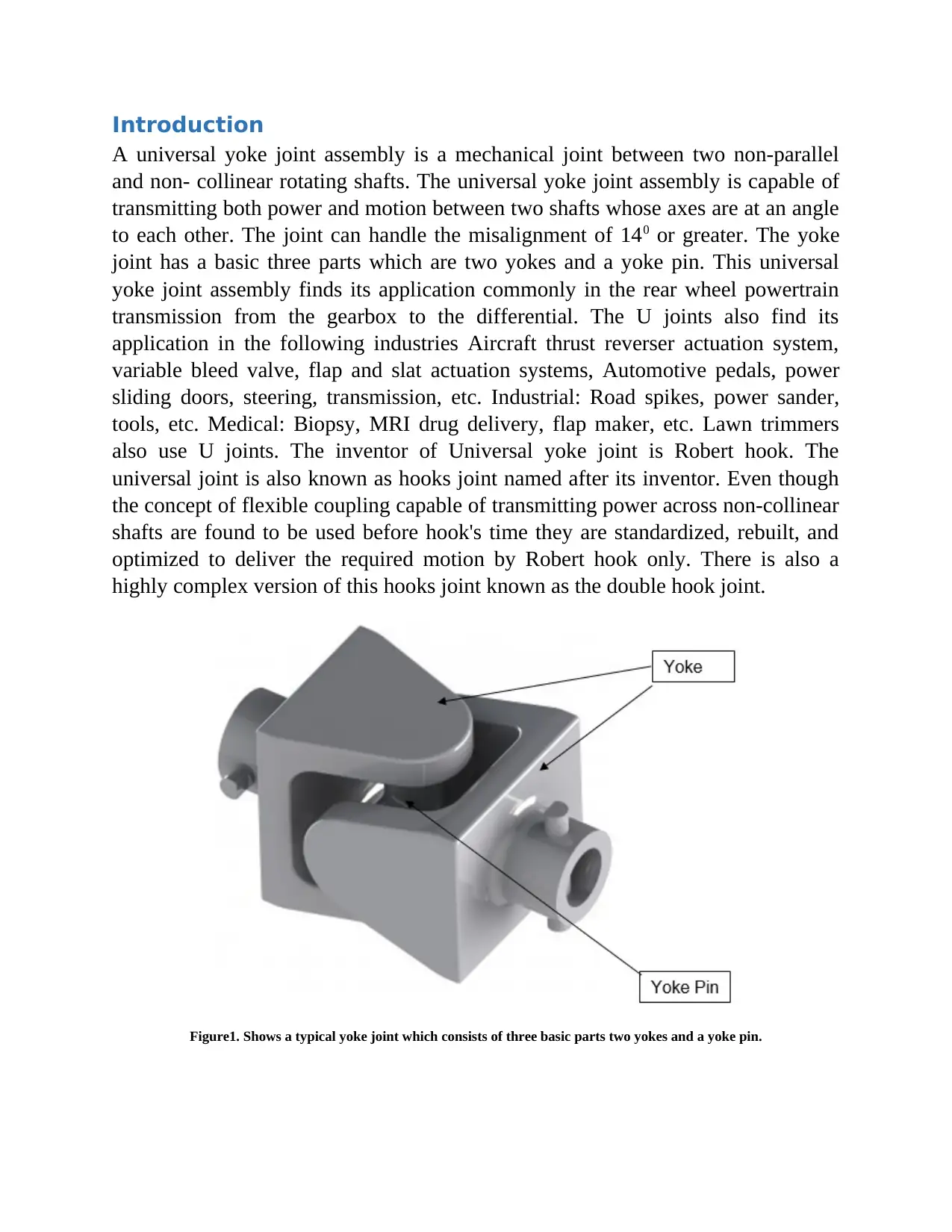
Introduction
A universal yoke joint assembly is a mechanical joint between two non-parallel
and non- collinear rotating shafts. The universal yoke joint assembly is capable of
transmitting both power and motion between two shafts whose axes are at an angle
to each other. The joint can handle the misalignment of 140 or greater. The yoke
joint has a basic three parts which are two yokes and a yoke pin. This universal
yoke joint assembly finds its application commonly in the rear wheel powertrain
transmission from the gearbox to the differential. The U joints also find its
application in the following industries Aircraft thrust reverser actuation system,
variable bleed valve, flap and slat actuation systems, Automotive pedals, power
sliding doors, steering, transmission, etc. Industrial: Road spikes, power sander,
tools, etc. Medical: Biopsy, MRI drug delivery, flap maker, etc. Lawn trimmers
also use U joints. The inventor of Universal yoke joint is Robert hook. The
universal joint is also known as hooks joint named after its inventor. Even though
the concept of flexible coupling capable of transmitting power across non-collinear
shafts are found to be used before hook's time they are standardized, rebuilt, and
optimized to deliver the required motion by Robert hook only. There is also a
highly complex version of this hooks joint known as the double hook joint.
Figure1. Shows a typical yoke joint which consists of three basic parts two yokes and a yoke pin.
Paraphrase This Document
Need a fresh take? Get an instant paraphrase of this document with our AI Paraphraser
Literature survey:
The literature survey on the Universal hooks joint is done on this chapter.
The need for the transmission of power within the shafts which are non-parallel
and non- linear raised many years before the time of hooks itself and they were
solved by many scientists. In the year 1664 Schott explained a work that a bevel
gear can be used to achieve an angled drive. The hooks designed and developed the
Universal joint to deliver its exact purpose until then there are many types of
research that are done on the hook’s joint in order to optimize the performance and
reduce the weight.
A.S.Bahrule & S.G. Solace(2014) investigated the stress distribution across the
joint for optimization under various loading conditions and across variable torques.
The torque that is applied on a steering rod is analyzed by observing the location of
the highest stress concentration areas and potential high load carrying areas then
the optimization is done on those areas and optimal performance is achieved.
Bijiagare & Mujabalie (2012), studied the behaviour of composite drive shaft made
up of carbon and epoxy to replace it with the conventional metal shafts for the
application of power transmission in automobiles. An algorithm known as the
generic algorithm has been used for the optimization of the drive shaft to achieve
high strength composites with the reduction in weight. The analysis was carried out
with the help of Ansys software.
Vesali & Kashfi (2012), in their research work, proposed the study of universal
joint dynamics in which the optimization of the performance characteristics of
joints are proposed. The process begins with the selection of equation of motion
which is associated with the behaviour of the motion of the universal hooks joint.
Which is supported by observing and analyzing the characteristics of the joint
during the transmission of torque and rotating speeds? An analytical method is
used in order to calculate the forces that are exerted on the joints. A numerical
model is also generated. The results were positive and the optimization was done
successfully.
Singh G & Singh R (2016) investigated the distribution of stress across the yoke of
the universal joint during the real world application conditions. The analysis was
also done on the same, the performance characteristics were improved by the
optimization of weigt. The reduction in weight is achieved by a reduction in
dimensions by function driven design.
Design and calculation:
The selection of the universal joint for a particular application is based on the
torque and the speed requirements.
The steps included in the design of universal joint are:
Step1:
Torque:
The maximum torque that is needed to be transmitted is the first selection criteria.
The calculation of the torque is on the basis of the engine horsepower/ motor
horsepower and the speed.
Applied Torque, Tapplied = HP x 63025/ N in (lb. x in.)
Tapplied = KW x 9550 / N in (Nm)
Where,
N is speed in RPM
KW is engine horsepower
Ts=¿Ta x Service factor
The service factor can be picked from the service factor table provided below.
Now let us say that we need to design a Universal joint for the transmission shaft
of an engine.
The engine specs are:
Max speed: 2800 Rpm
Max torque: 47 Nm @ 1900 Rpm
Max Hp : 17 Hp @ 2800 Rpm
⊘ This is a preview!⊘
Do you want full access?
Subscribe today to unlock all pages.
Trusted by 1+ million students worldwide
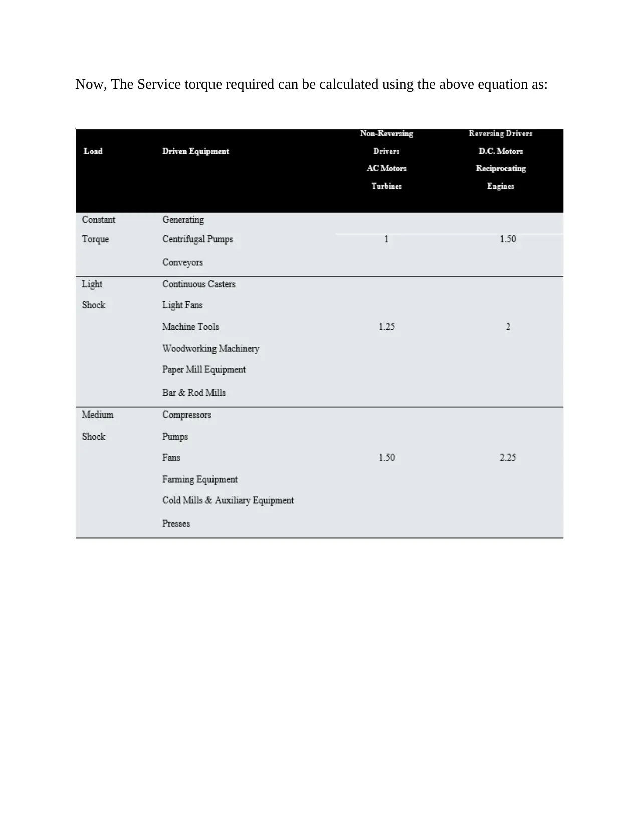
Now, The Service torque required can be calculated using the above equation as:
Paraphrase This Document
Need a fresh take? Get an instant paraphrase of this document with our AI Paraphraser
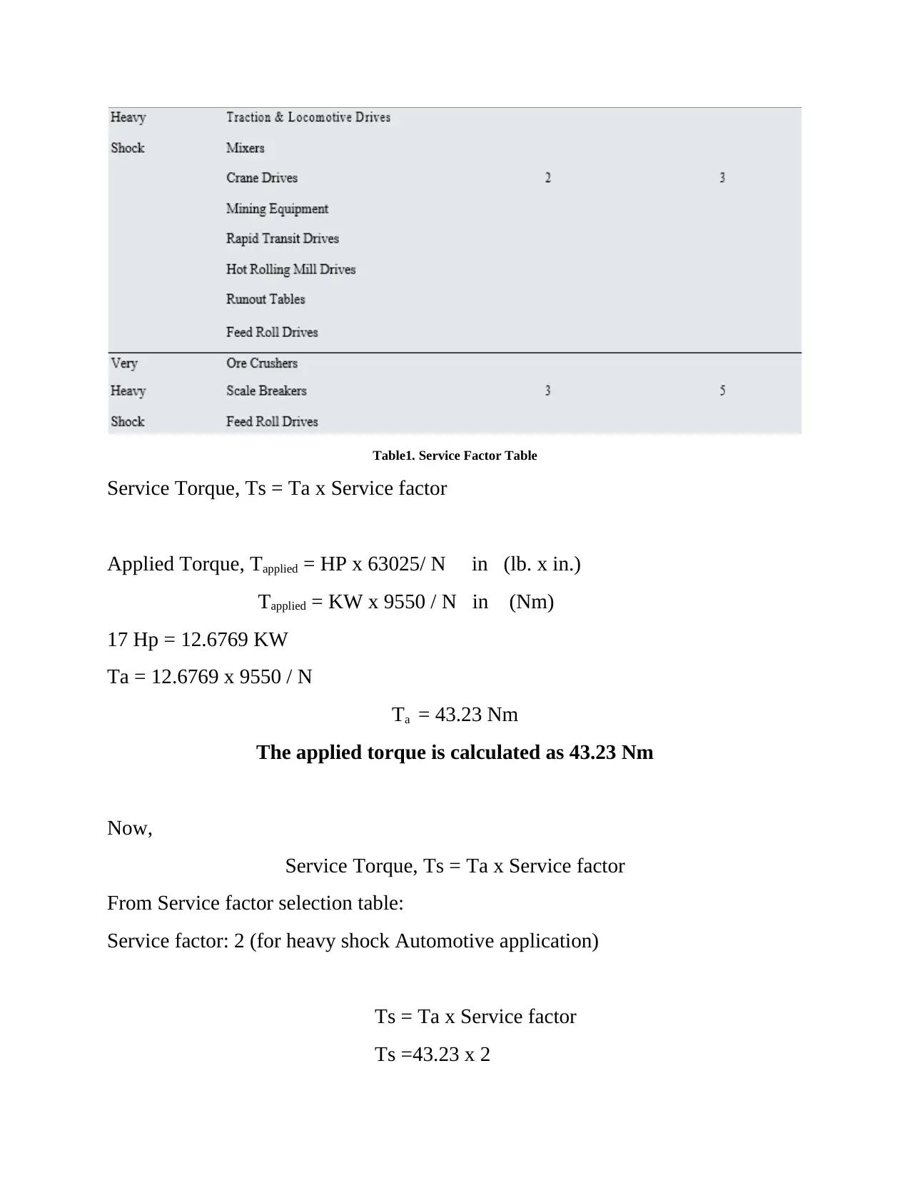
Table1. Service Factor Table
Service Torque, Ts = Ta x Service factor
Applied Torque, Tapplied = HP x 63025/ N in (lb. x in.)
Tapplied = KW x 9550 / N in (Nm)
17 Hp = 12.6769 KW
Ta = 12.6769 x 9550 / N
Ta = 43.23 Nm
The applied torque is calculated as 43.23 Nm
Now,
Service Torque, Ts = Ta x Service factor
From Service factor selection table:
Service factor: 2 (for heavy shock Automotive application)
Ts = Ta x Service factor
Ts =43.23 x 2
Service Torque, Ts = Ta x Service factor
Applied Torque, Tapplied = HP x 63025/ N in (lb. x in.)
Tapplied = KW x 9550 / N in (Nm)
17 Hp = 12.6769 KW
Ta = 12.6769 x 9550 / N
Ta = 43.23 Nm
The applied torque is calculated as 43.23 Nm
Now,
Service Torque, Ts = Ta x Service factor
From Service factor selection table:
Service factor: 2 (for heavy shock Automotive application)
Ts = Ta x Service factor
Ts =43.23 x 2
Ts = 86.47 Nm
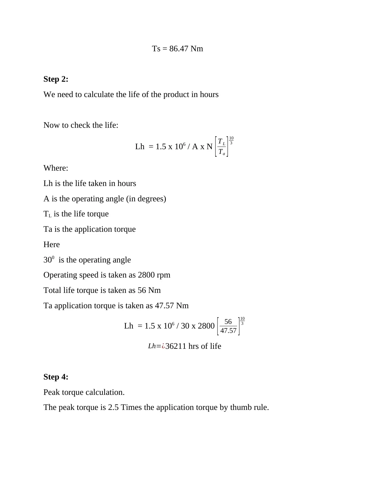
Step 2:
We need to calculate the life of the product in hours
Now to check the life:
Lh = 1.5 x 10⁶ / A x N [ T L
Ta ]10
3
Where:
Lh is the life taken in hours
A is the operating angle (in degrees)
TL is the life torque
Ta is the application torque
Here
300 is the operating angle
Operating speed is taken as 2800 rpm
Total life torque is taken as 56 Nm
Ta application torque is taken as 47.57 Nm
Lh = 1.5 x 10⁶ / 30 x 2800 [ 56
47.57 ]10
3
Lh=¿36211 hrs of life
Step 4:
Peak torque calculation.
The peak torque is 2.5 Times the application torque by thumb rule.
⊘ This is a preview!⊘
Do you want full access?
Subscribe today to unlock all pages.
Trusted by 1+ million students worldwide
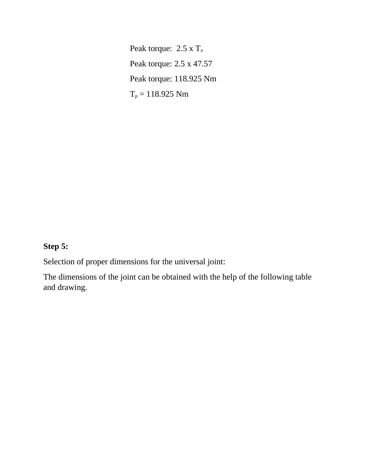
Peak torque: 2.5 x Ta
Peak torque: 2.5 x 47.57
Peak torque: 118.925 Nm
Tp = 118.925 Nm
Step 5:
Selection of proper dimensions for the universal joint:
The dimensions of the joint can be obtained with the help of the following table
and drawing.
Peak torque: 2.5 x 47.57
Peak torque: 118.925 Nm
Tp = 118.925 Nm
Step 5:
Selection of proper dimensions for the universal joint:
The dimensions of the joint can be obtained with the help of the following table
and drawing.
Paraphrase This Document
Need a fresh take? Get an instant paraphrase of this document with our AI Paraphraser
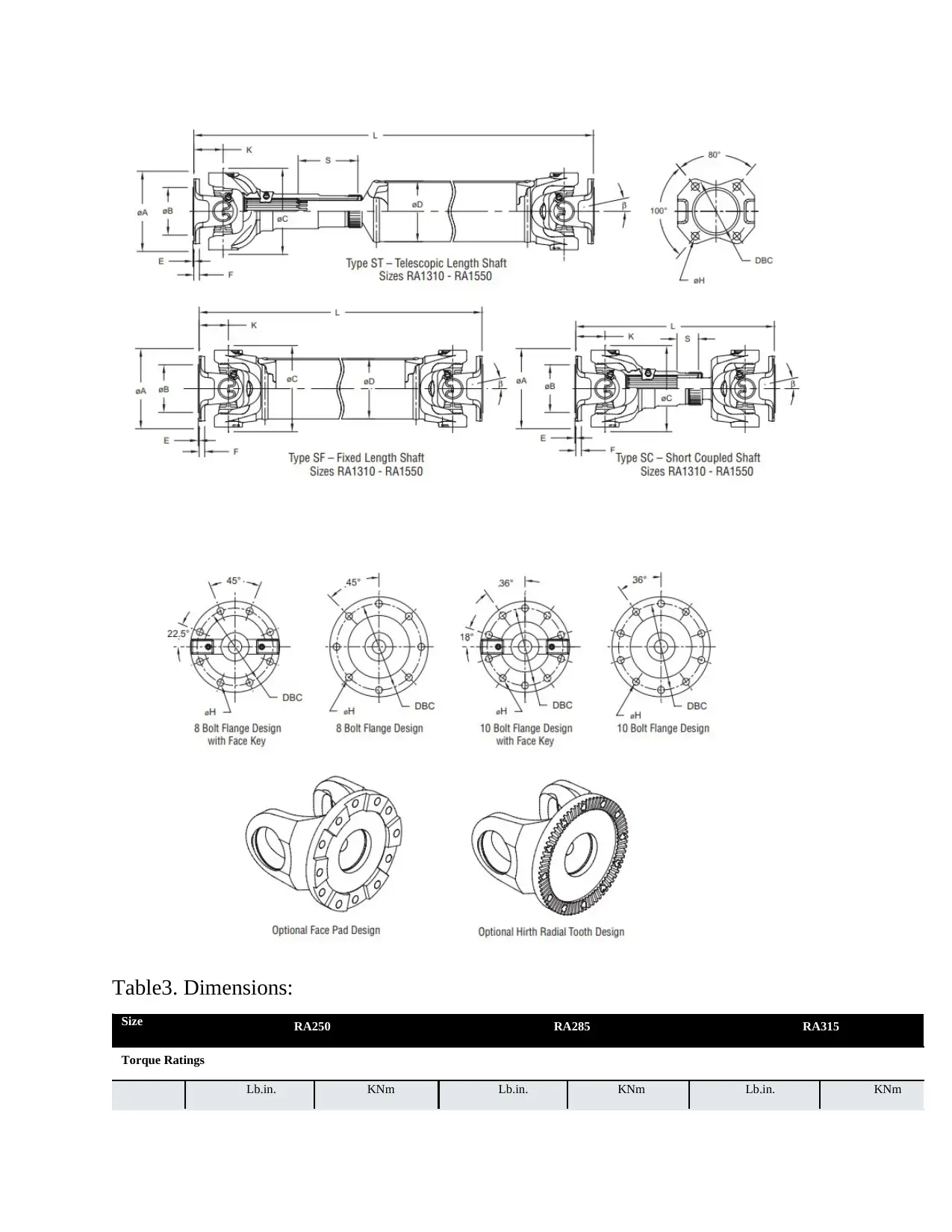
Table3. Dimensions:
Size RA250 RA285 RA315
Torque Ratings
Lb.in. KNm Lb.in. KNm Lb.in. KNm
Size RA250 RA285 RA315
Torque Ratings
Lb.in. KNm Lb.in. KNm Lb.in. KNm
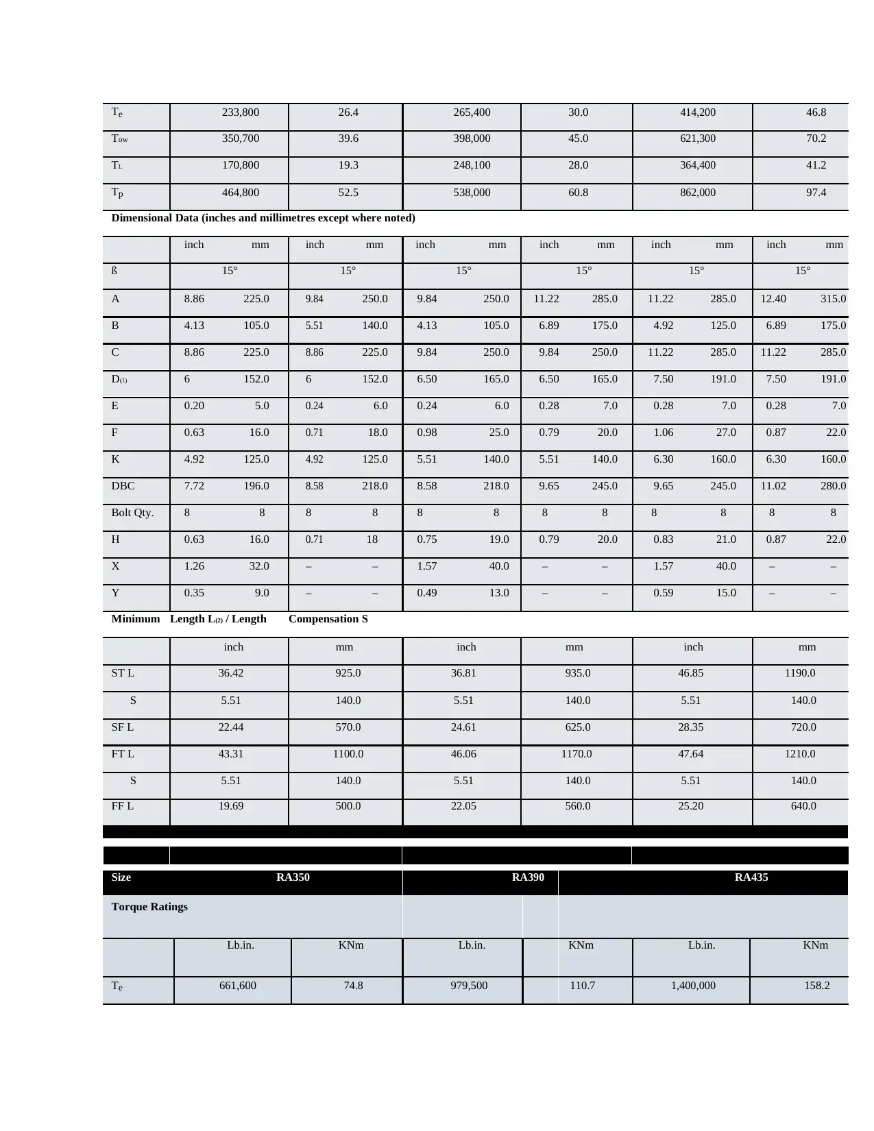
Te 233,800 26.4 265,400 30.0 414,200 46.8
Tow 350,700 39.6 398,000 45.0 621,300 70.2
TL 170,800 19.3 248,100 28.0 364,400 41.2
Tp 464,800 52.5 538,000 60.8 862,000 97.4
Dimensional Data (inches and millimetres except where noted)
inch mm inch mm inch mm inch mm inch mm inch mm
ß 15° 15° 15° 15° 15° 15°
A 8.86 225.0 9.84 250.0 9.84 250.0 11.22 285.0 11.22 285.0 12.40 315.0
B 4.13 105.0 5.51 140.0 4.13 105.0 6.89 175.0 4.92 125.0 6.89 175.0
C 8.86 225.0 8.86 225.0 9.84 250.0 9.84 250.0 11.22 285.0 11.22 285.0
D(1) 6 152.0 6 152.0 6.50 165.0 6.50 165.0 7.50 191.0 7.50 191.0
E 0.20 5.0 0.24 6.0 0.24 6.0 0.28 7.0 0.28 7.0 0.28 7.0
F 0.63 16.0 0.71 18.0 0.98 25.0 0.79 20.0 1.06 27.0 0.87 22.0
K 4.92 125.0 4.92 125.0 5.51 140.0 5.51 140.0 6.30 160.0 6.30 160.0
DBC 7.72 196.0 8.58 218.0 8.58 218.0 9.65 245.0 9.65 245.0 11.02 280.0
Bolt Qty. 8 8 8 8 8 8 8 8 8 8 8 8
H 0.63 16.0 0.71 18 0.75 19.0 0.79 20.0 0.83 21.0 0.87 22.0
X 1.26 32.0 – – 1.57 40.0 – – 1.57 40.0 – –
Y 0.35 9.0 – – 0.49 13.0 – – 0.59 15.0 – –
Minimum Length L(2) / Length Compensation S
inch mm inch mm inch mm
ST L 36.42 925.0 36.81 935.0 46.85 1190.0
S 5.51 140.0 5.51 140.0 5.51 140.0
SF L 22.44 570.0 24.61 625.0 28.35 720.0
FT L 43.31 1100.0 46.06 1170.0 47.64 1210.0
S 5.51 140.0 5.51 140.0 5.51 140.0
FF L 19.69 500.0 22.05 560.0 25.20 640.0
Size RA350 RA390 RA435
Torque Ratings
Lb.in. KNm Lb.in. KNm Lb.in. KNm
Te 661,600 74.8 979,500 110.7 1,400,000 158.2
⊘ This is a preview!⊘
Do you want full access?
Subscribe today to unlock all pages.
Trusted by 1+ million students worldwide
1 out of 27
Your All-in-One AI-Powered Toolkit for Academic Success.
+13062052269
info@desklib.com
Available 24*7 on WhatsApp / Email
![[object Object]](/_next/static/media/star-bottom.7253800d.svg)
Unlock your academic potential
Copyright © 2020–2026 A2Z Services. All Rights Reserved. Developed and managed by ZUCOL.