Software Design Document: Zoo Manager Application Project
VerifiedAdded on 2023/06/12
|15
|2214
|495
Project
AI Summary
This document presents a comprehensive software design for a Zoo Manager application. It includes an introduction outlining the purpose and scope of the project, followed by an overview of the document's structure. The system architecture is detailed with class diagrams illustrating the relationships between different modules such as Bird, Reptile, Mammal, and the ZooOrganizer. The design incorporates exception handling for invalid animal names. Data design specifies data descriptions and a data dictionary, outlining objects, attributes, and methods. Component design elaborates on the classes used, including Animal, AnimalImpl, Bird, Reptile, Mammal, ZooOrganizer, and InvalidAnimalException. The human interface design provides an overview of the user interface, screen images, and object actions. Finally, a requirements matrix maps out the data structure and relevant references. Desklib provides access to this and other solved assignments to aid students in their studies.
Software Design Description
Version <1.0>
<2018.06.18>
<Zoo Manager>
<Student Name>
i
Version <1.0>
<2018.06.18>
<Zoo Manager>
<Student Name>
i
Paraphrase This Document
Need a fresh take? Get an instant paraphrase of this document with our AI Paraphraser
Table of Contents
Table of Contents
Table of Contents.............................................................................................................................................ii
List of Figures.................................................................................................................................................iii
1.0. Introduction..........................................................................................................................................1
1.1. Purpose..................................................................................................................................................1
1.2. Scope.....................................................................................................................................................1
1.3. Glossary.................................................................................................................................................1
1.4. References.............................................................................................................................................3
2.0 . Overview of Document............................................................................................................................3
3.0 System Architecture...................................................................................................................................5
3.0.1 Architectural Design............................................................................................................................5
3.2 Decomposition Description....................................................................................................................6
3. 3 Exception Handling...............................................................................................................................7
3.4 Design Rationale....................................................................................................................................7
4 Data Design...................................................................................................................................................8
4.1 Data description......................................................................................................................................8
4.2 Data Dictionary......................................................................................................................................8
5 Component Design........................................................................................................................................9
6 Human Interface Design..............................................................................................................................12
6.1 Overview of User Interface..................................................................................................................12
6.2 Screen Images.......................................................................................................................................13
6.3 Screen Objects and Actions..................................................................................................................13
7. Requirements Matrix..................................................................................................................................14
ii
List of Figures
Figure 1 Class Diagram For zoo organizer.....................................................................................................5
Figure 2 class diagram for Bird.......................................................................................................................6
Figure 3 class diagram for reptile....................................................................................................................6
Figure 4 class diagram for Mammal................................................................................................................6
Figure 5 class diagram for Zoo Organizer........................................................................................................6
Figure 6 User Interface...................................................................................................................................13
iii
⊘ This is a preview!⊘
Do you want full access?
Subscribe today to unlock all pages.
Trusted by 1+ million students worldwide
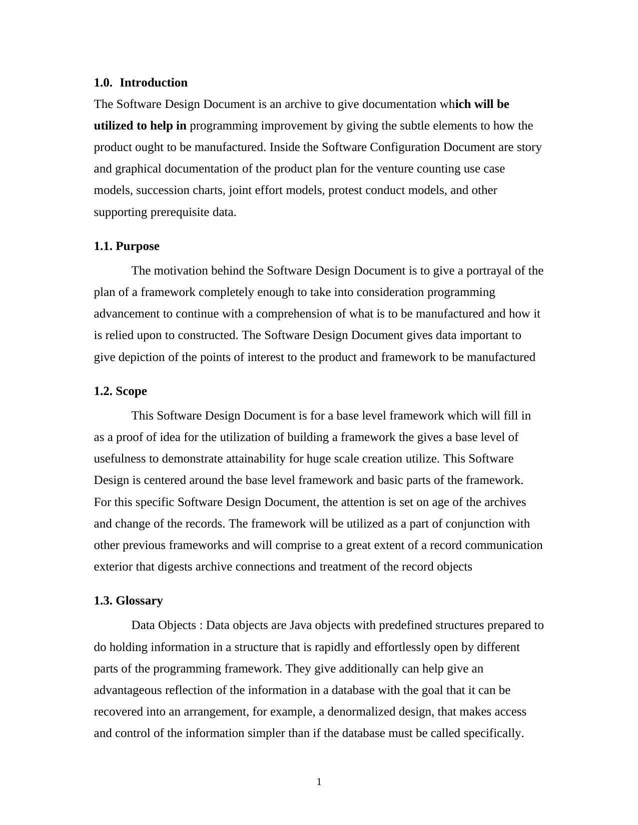
1.0. Introduction
The Software Design Document is an archive to give documentation which will be
utilized to help in programming improvement by giving the subtle elements to how the
product ought to be manufactured. Inside the Software Configuration Document are story
and graphical documentation of the product plan for the venture counting use case
models, succession charts, joint effort models, protest conduct models, and other
supporting prerequisite data.
1.1. Purpose
The motivation behind the Software Design Document is to give a portrayal of the
plan of a framework completely enough to take into consideration programming
advancement to continue with a comprehension of what is to be manufactured and how it
is relied upon to constructed. The Software Design Document gives data important to
give depiction of the points of interest to the product and framework to be manufactured
1.2. Scope
This Software Design Document is for a base level framework which will fill in
as a proof of idea for the utilization of building a framework the gives a base level of
usefulness to demonstrate attainability for huge scale creation utilize. This Software
Design is centered around the base level framework and basic parts of the framework.
For this specific Software Design Document, the attention is set on age of the archives
and change of the records. The framework will be utilized as a part of conjunction with
other previous frameworks and will comprise to a great extent of a record communication
exterior that digests archive connections and treatment of the record objects
1.3. Glossary
Data Objects : Data objects are Java objects with predefined structures prepared to
do holding information in a structure that is rapidly and effortlessly open by different
parts of the programming framework. They give additionally can help give an
advantageous reflection of the information in a database with the goal that it can be
recovered into an arrangement, for example, a denormalized design, that makes access
and control of the information simpler than if the database must be called specifically.
1
Paraphrase This Document
Need a fresh take? Get an instant paraphrase of this document with our AI Paraphraser
● JDBC/ODBC – These two acronyms remain for Java Database Connectivity and Open
Database Connectivity API's which take into consideration institutionalized database
access and cooperation from programming items.
1.4. References
XML Legal Documents Utility Software Development Plan
○ Version 1.0, Latest update on 2018-06-18
2.0 . Overview of Document
The Software Design Document is divided into 11 sections with various
subsections. The
sections of the Software Design Document are:
Introduction
Glossary
Design Overview
System architecture
Data Design
Component Design
Human Interface Design
Requirements Matrix
2
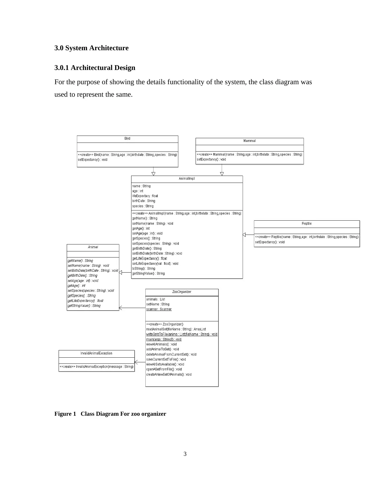
3.0 System Architecture
3.0.1 Architectural Design
For the purpose of showing the details functionality of the system, the class diagram was
used to represent the same.
Figure 1 Class Diagram For zoo organizer
3
3.0.1 Architectural Design
For the purpose of showing the details functionality of the system, the class diagram was
used to represent the same.
Figure 1 Class Diagram For zoo organizer
3
⊘ This is a preview!⊘
Do you want full access?
Subscribe today to unlock all pages.
Trusted by 1+ million students worldwide
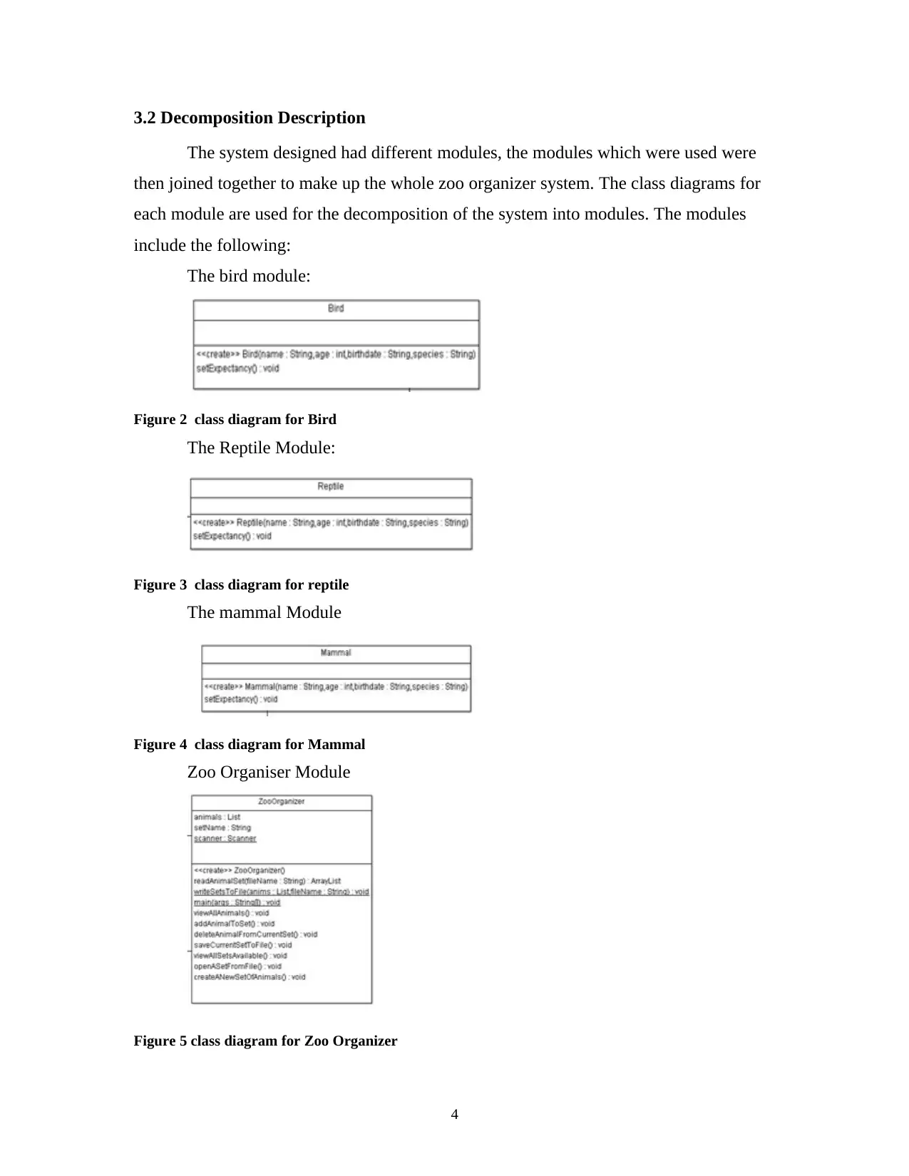
3.2 Decomposition Description
The system designed had different modules, the modules which were used were
then joined together to make up the whole zoo organizer system. The class diagrams for
each module are used for the decomposition of the system into modules. The modules
include the following:
The bird module:
Figure 2 class diagram for Bird
The Reptile Module:
Figure 3 class diagram for reptile
The mammal Module
Figure 4 class diagram for Mammal
Zoo Organiser Module
Figure 5 class diagram for Zoo Organizer
4
Paraphrase This Document
Need a fresh take? Get an instant paraphrase of this document with our AI Paraphraser
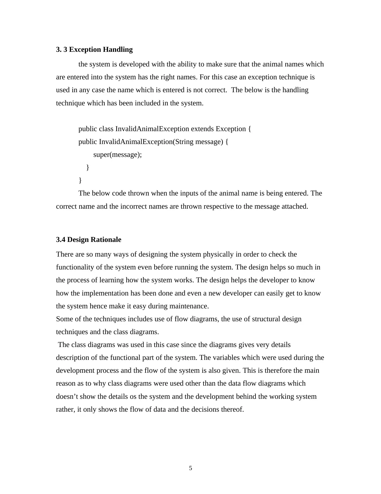
3. 3 Exception Handling
the system is developed with the ability to make sure that the animal names which
are entered into the system has the right names. For this case an exception technique is
used in any case the name which is entered is not correct. The below is the handling
technique which has been included in the system.
public class InvalidAnimalException extends Exception {
public InvalidAnimalException(String message) {
super(message);
}
}
The below code thrown when the inputs of the animal name is being entered. The
correct name and the incorrect names are thrown respective to the message attached.
3.4 Design Rationale
There are so many ways of designing the system physically in order to check the
functionality of the system even before running the system. The design helps so much in
the process of learning how the system works. The design helps the developer to know
how the implementation has been done and even a new developer can easily get to know
the system hence make it easy during maintenance.
Some of the techniques includes use of flow diagrams, the use of structural design
techniques and the class diagrams.
The class diagrams was used in this case since the diagrams gives very details
description of the functional part of the system. The variables which were used during the
development process and the flow of the system is also given. This is therefore the main
reason as to why class diagrams were used other than the data flow diagrams which
doesn’t show the details os the system and the development behind the working system
rather, it only shows the flow of data and the decisions thereof.
5
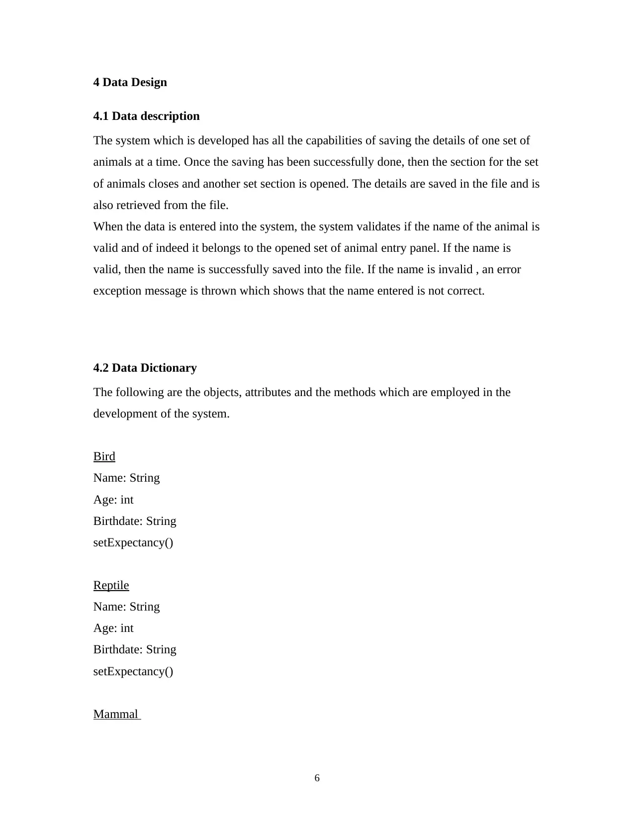
4 Data Design
4.1 Data description
The system which is developed has all the capabilities of saving the details of one set of
animals at a time. Once the saving has been successfully done, then the section for the set
of animals closes and another set section is opened. The details are saved in the file and is
also retrieved from the file.
When the data is entered into the system, the system validates if the name of the animal is
valid and of indeed it belongs to the opened set of animal entry panel. If the name is
valid, then the name is successfully saved into the file. If the name is invalid , an error
exception message is thrown which shows that the name entered is not correct.
4.2 Data Dictionary
The following are the objects, attributes and the methods which are employed in the
development of the system.
Bird
Name: String
Age: int
Birthdate: String
setExpectancy()
Reptile
Name: String
Age: int
Birthdate: String
setExpectancy()
Mammal
6
⊘ This is a preview!⊘
Do you want full access?
Subscribe today to unlock all pages.
Trusted by 1+ million students worldwide
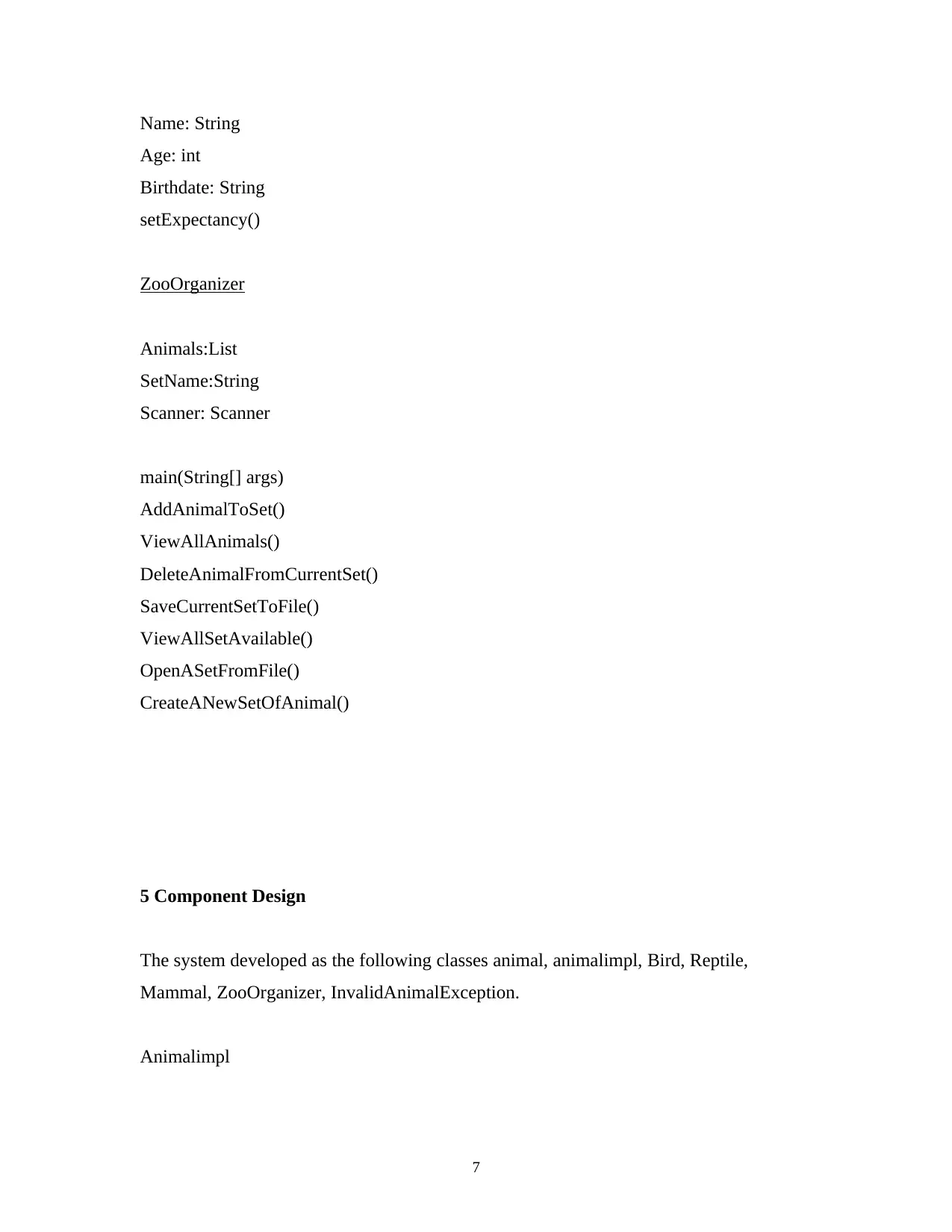
Name: String
Age: int
Birthdate: String
setExpectancy()
ZooOrganizer
Animals:List
SetName:String
Scanner: Scanner
main(String[] args)
AddAnimalToSet()
ViewAllAnimals()
DeleteAnimalFromCurrentSet()
SaveCurrentSetToFile()
ViewAllSetAvailable()
OpenASetFromFile()
CreateANewSetOfAnimal()
5 Component Design
The system developed as the following classes animal, animalimpl, Bird, Reptile,
Mammal, ZooOrganizer, InvalidAnimalException.
Animalimpl
7
Paraphrase This Document
Need a fresh take? Get an instant paraphrase of this document with our AI Paraphraser
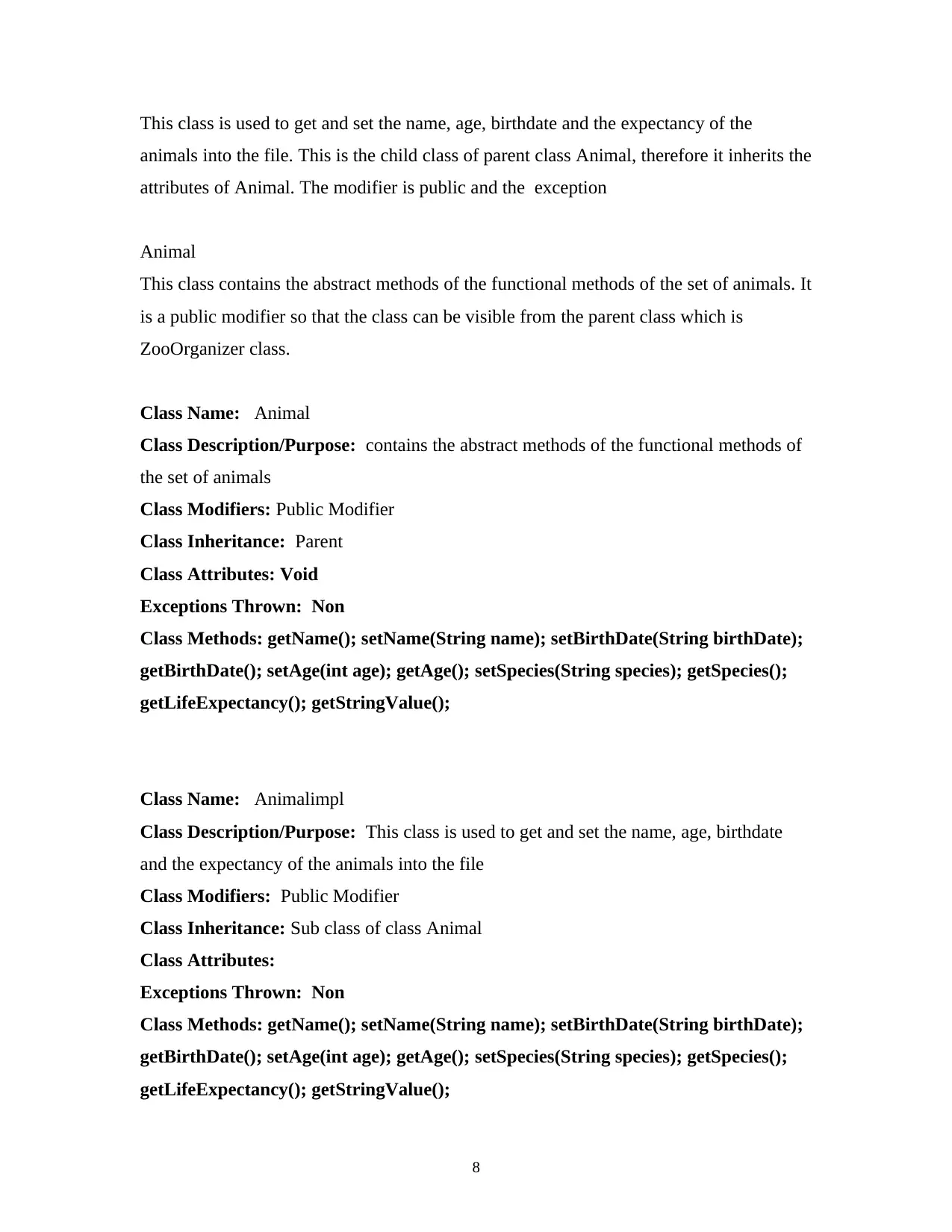
This class is used to get and set the name, age, birthdate and the expectancy of the
animals into the file. This is the child class of parent class Animal, therefore it inherits the
attributes of Animal. The modifier is public and the exception
Animal
This class contains the abstract methods of the functional methods of the set of animals. It
is a public modifier so that the class can be visible from the parent class which is
ZooOrganizer class.
Class Name: Animal
Class Description/Purpose: contains the abstract methods of the functional methods of
the set of animals
Class Modifiers: Public Modifier
Class Inheritance: Parent
Class Attributes: Void
Exceptions Thrown: Non
Class Methods: getName(); setName(String name); setBirthDate(String birthDate);
getBirthDate(); setAge(int age); getAge(); setSpecies(String species); getSpecies();
getLifeExpectancy(); getStringValue();
Class Name: Animalimpl
Class Description/Purpose: This class is used to get and set the name, age, birthdate
and the expectancy of the animals into the file
Class Modifiers: Public Modifier
Class Inheritance: Sub class of class Animal
Class Attributes:
Exceptions Thrown: Non
Class Methods: getName(); setName(String name); setBirthDate(String birthDate);
getBirthDate(); setAge(int age); getAge(); setSpecies(String species); getSpecies();
getLifeExpectancy(); getStringValue();
8
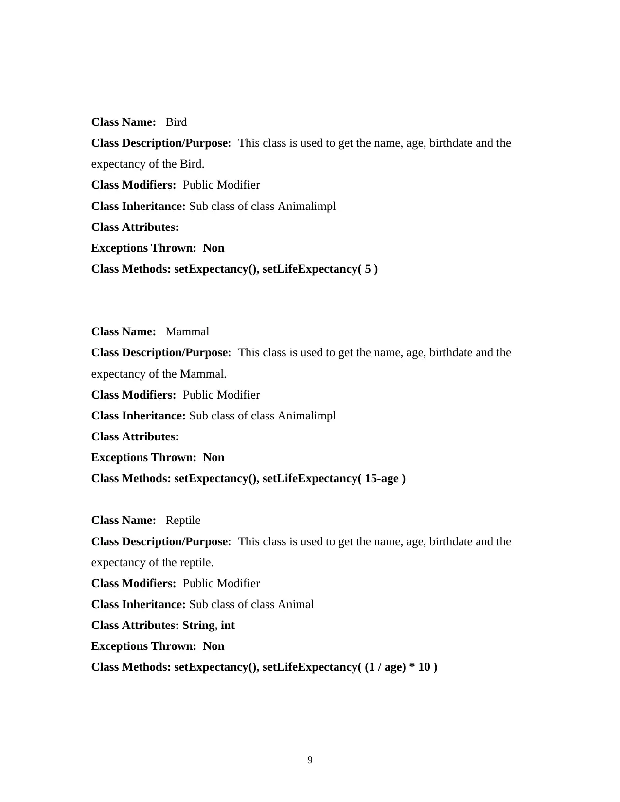
Class Name: Bird
Class Description/Purpose: This class is used to get the name, age, birthdate and the
expectancy of the Bird.
Class Modifiers: Public Modifier
Class Inheritance: Sub class of class Animalimpl
Class Attributes:
Exceptions Thrown: Non
Class Methods: setExpectancy(), setLifeExpectancy( 5 )
Class Name: Mammal
Class Description/Purpose: This class is used to get the name, age, birthdate and the
expectancy of the Mammal.
Class Modifiers: Public Modifier
Class Inheritance: Sub class of class Animalimpl
Class Attributes:
Exceptions Thrown: Non
Class Methods: setExpectancy(), setLifeExpectancy( 15-age )
Class Name: Reptile
Class Description/Purpose: This class is used to get the name, age, birthdate and the
expectancy of the reptile.
Class Modifiers: Public Modifier
Class Inheritance: Sub class of class Animal
Class Attributes: String, int
Exceptions Thrown: Non
Class Methods: setExpectancy(), setLifeExpectancy( (1 / age) * 10 )
9
Class Description/Purpose: This class is used to get the name, age, birthdate and the
expectancy of the Bird.
Class Modifiers: Public Modifier
Class Inheritance: Sub class of class Animalimpl
Class Attributes:
Exceptions Thrown: Non
Class Methods: setExpectancy(), setLifeExpectancy( 5 )
Class Name: Mammal
Class Description/Purpose: This class is used to get the name, age, birthdate and the
expectancy of the Mammal.
Class Modifiers: Public Modifier
Class Inheritance: Sub class of class Animalimpl
Class Attributes:
Exceptions Thrown: Non
Class Methods: setExpectancy(), setLifeExpectancy( 15-age )
Class Name: Reptile
Class Description/Purpose: This class is used to get the name, age, birthdate and the
expectancy of the reptile.
Class Modifiers: Public Modifier
Class Inheritance: Sub class of class Animal
Class Attributes: String, int
Exceptions Thrown: Non
Class Methods: setExpectancy(), setLifeExpectancy( (1 / age) * 10 )
9
⊘ This is a preview!⊘
Do you want full access?
Subscribe today to unlock all pages.
Trusted by 1+ million students worldwide
1 out of 15
Related Documents

Your All-in-One AI-Powered Toolkit for Academic Success.
+13062052269
info@desklib.com
Available 24*7 on WhatsApp / Email
![[object Object]](/_next/static/media/star-bottom.7253800d.svg)
Unlock your academic potential
Copyright © 2020–2026 A2Z Services. All Rights Reserved. Developed and managed by ZUCOL.