Speed Control of D.C Motor
Added on 2023-03-31
15 Pages2246 Words372 Views
1
Student
Instructor
Speed Control of D.C Motor
Date
Student
Instructor
Speed Control of D.C Motor
Date

2
Introduction
A D.C motor is a rotary electrical device that converts D.C electrical power into rotational
mechanical power. There are different types of D.C motors defined by the type and connection
of magnetic excitation circuit network. These types include series motors, shunt motors,
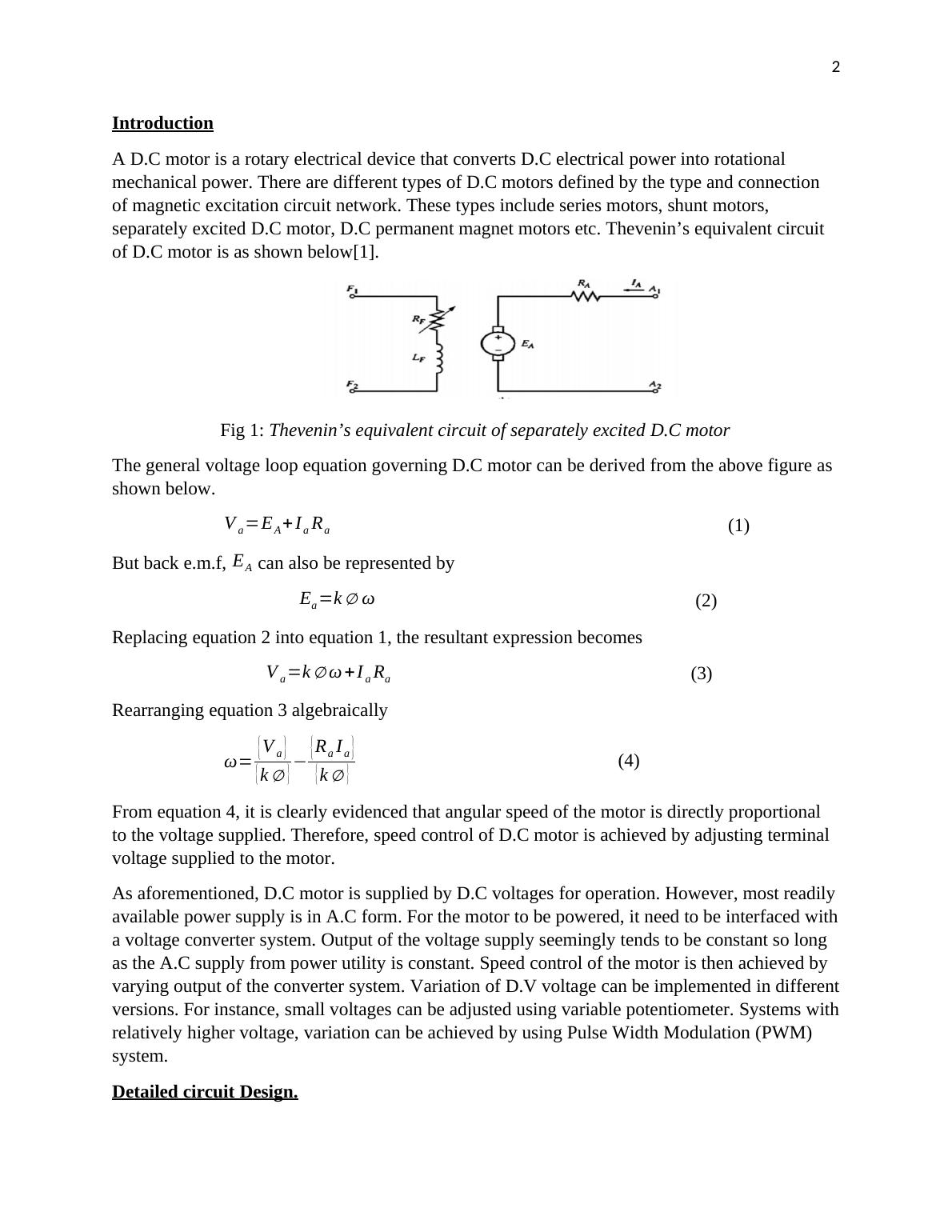
separately excited D.C motor, D.C permanent magnet motors etc. Thevenin’s equivalent circuit
of D.C motor is as shown below[1].
Fig 1: Thevenin’s equivalent circuit of separately excited D.C motor
The general voltage loop equation governing D.C motor can be derived from the above figure as
shown below.
V a =EA + Ia Ra (1)
But back e.m.f, EA can also be represented by
Ea =k ∅ ω (2)
Replacing equation 2 into equation 1, the resultant expression becomes
V a =k ∅ω + I a Ra (3)
Rearranging equation 3 algebraically
ω= {V a }
{ k ∅ } − {Ra Ia }
{ k ∅ } (4)
From equation 4, it is clearly evidenced that angular speed of the motor is directly proportional
to the voltage supplied. Therefore, speed control of D.C motor is achieved by adjusting terminal
voltage supplied to the motor.
As aforementioned, D.C motor is supplied by D.C voltages for operation. However, most readily
available power supply is in A.C form. For the motor to be powered, it need to be interfaced with
a voltage converter system. Output of the voltage supply seemingly tends to be constant so long
as the A.C supply from power utility is constant. Speed control of the motor is then achieved by
varying output of the converter system. Variation of D.V voltage can be implemented in different
versions. For instance, small voltages can be adjusted using variable potentiometer. Systems with
relatively higher voltage, variation can be achieved by using Pulse Width Modulation (PWM)
system.
Detailed circuit Design.
Introduction
A D.C motor is a rotary electrical device that converts D.C electrical power into rotational
mechanical power. There are different types of D.C motors defined by the type and connection
of magnetic excitation circuit network. These types include series motors, shunt motors,
separately excited D.C motor, D.C permanent magnet motors etc. Thevenin’s equivalent circuit
of D.C motor is as shown below[1].
Fig 1: Thevenin’s equivalent circuit of separately excited D.C motor
The general voltage loop equation governing D.C motor can be derived from the above figure as
shown below.
V a =EA + Ia Ra (1)
But back e.m.f, EA can also be represented by
Ea =k ∅ ω (2)
Replacing equation 2 into equation 1, the resultant expression becomes
V a =k ∅ω + I a Ra (3)
Rearranging equation 3 algebraically
ω= {V a }
{ k ∅ } − {Ra Ia }
{ k ∅ } (4)
From equation 4, it is clearly evidenced that angular speed of the motor is directly proportional
to the voltage supplied. Therefore, speed control of D.C motor is achieved by adjusting terminal
voltage supplied to the motor.
As aforementioned, D.C motor is supplied by D.C voltages for operation. However, most readily
available power supply is in A.C form. For the motor to be powered, it need to be interfaced with
a voltage converter system. Output of the voltage supply seemingly tends to be constant so long
as the A.C supply from power utility is constant. Speed control of the motor is then achieved by
varying output of the converter system. Variation of D.V voltage can be implemented in different
versions. For instance, small voltages can be adjusted using variable potentiometer. Systems with
relatively higher voltage, variation can be achieved by using Pulse Width Modulation (PWM)
system.
Detailed circuit Design.
3
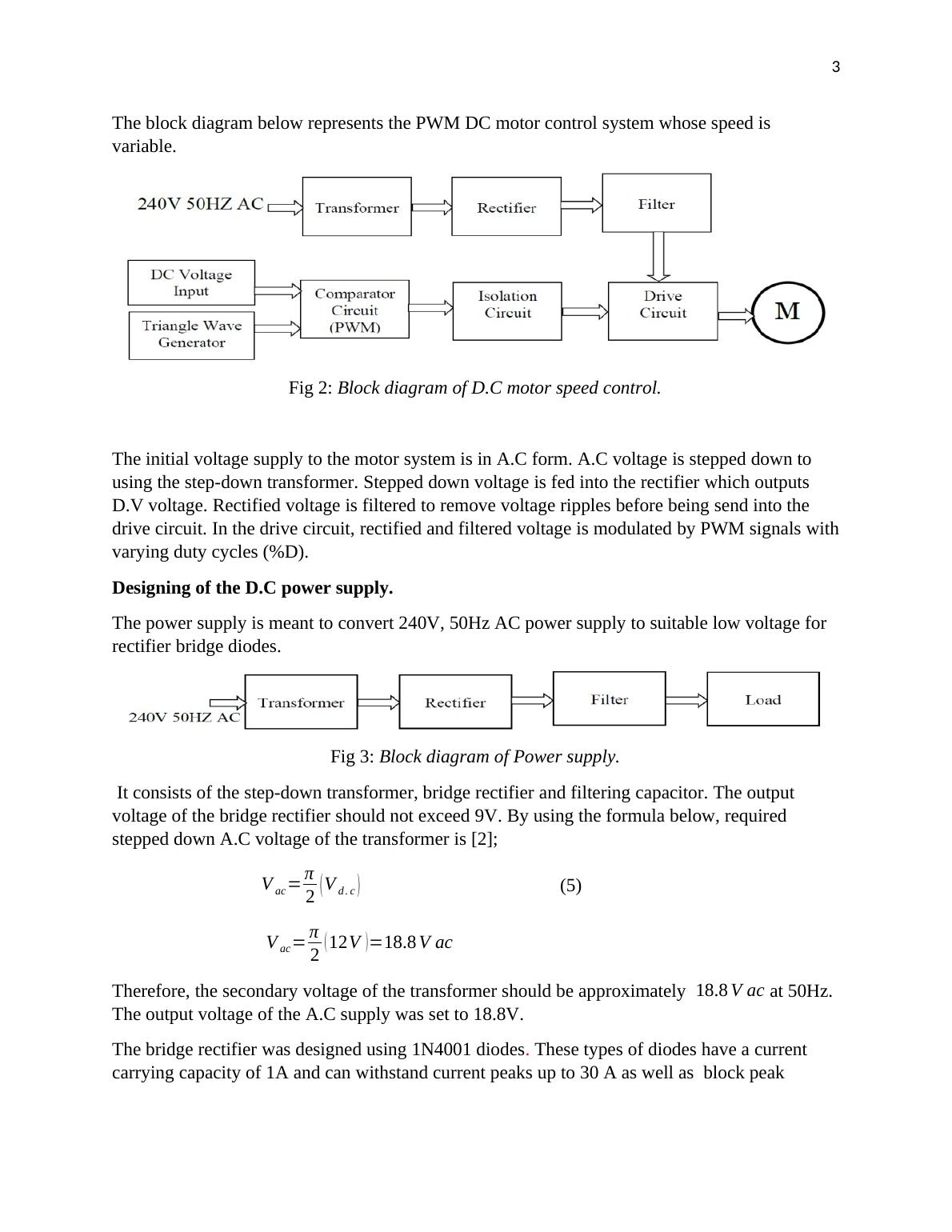
The block diagram below represents the PWM DC motor control system whose speed is
variable.
Fig 2: Block diagram of D.C motor speed control.
The initial voltage supply to the motor system is in A.C form. A.C voltage is stepped down to
using the step-down transformer. Stepped down voltage is fed into the rectifier which outputs
D.V voltage. Rectified voltage is filtered to remove voltage ripples before being send into the
drive circuit. In the drive circuit, rectified and filtered voltage is modulated by PWM signals with
varying duty cycles (%D).
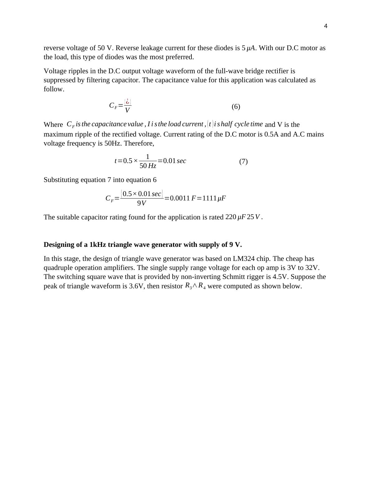
Designing of the D.C power supply.
The power supply is meant to convert 240V, 50Hz AC power supply to suitable low voltage for
rectifier bridge diodes.
Fig 3: Block diagram of Power supply.
It consists of the step-down transformer, bridge rectifier and filtering capacitor. The output
voltage of the bridge rectifier should not exceed 9V. By using the formula below, required
stepped down A.C voltage of the transformer is [2];
V ac = π
2 ( V d . c ) (5)
V ac = π
2 ( 12V )=18.8 V ac
Therefore, the secondary voltage of the transformer should be approximately 18.8 V ac at 50Hz.
The output voltage of the A.C supply was set to 18.8V.
The bridge rectifier was designed using 1N4001 diodes. These types of diodes have a current
carrying capacity of 1A and can withstand current peaks up to 30 A as well as block peak
The block diagram below represents the PWM DC motor control system whose speed is
variable.
Fig 2: Block diagram of D.C motor speed control.
The initial voltage supply to the motor system is in A.C form. A.C voltage is stepped down to
using the step-down transformer. Stepped down voltage is fed into the rectifier which outputs
D.V voltage. Rectified voltage is filtered to remove voltage ripples before being send into the
drive circuit. In the drive circuit, rectified and filtered voltage is modulated by PWM signals with
varying duty cycles (%D).
Designing of the D.C power supply.
The power supply is meant to convert 240V, 50Hz AC power supply to suitable low voltage for
rectifier bridge diodes.
Fig 3: Block diagram of Power supply.
It consists of the step-down transformer, bridge rectifier and filtering capacitor. The output
voltage of the bridge rectifier should not exceed 9V. By using the formula below, required
stepped down A.C voltage of the transformer is [2];
V ac = π
2 ( V d . c ) (5)
V ac = π
2 ( 12V )=18.8 V ac
Therefore, the secondary voltage of the transformer should be approximately 18.8 V ac at 50Hz.
The output voltage of the A.C supply was set to 18.8V.
The bridge rectifier was designed using 1N4001 diodes. These types of diodes have a current
carrying capacity of 1A and can withstand current peaks up to 30 A as well as block peak
4
reverse voltage of 50 V. Reverse leakage current for these diodes is 5 μA. With our D.C motor as
the load, this type of diodes was the most preferred.
Voltage ripples in the D.C output voltage waveform of the full-wave bridge rectifier is
suppressed by filtering capacitor. The capacitance value for this application was calculated as
follow.
CF = { ¿ }
V (6)
Where CF is the capacitance value , I i s the load current , ( t ) i s half cycle time and V is the
maximum ripple of the rectified voltage. Current rating of the D.C motor is 0.5A and A.C mains
voltage frequency is 50Hz. Therefore,
t=0.5 × 1
50 Hz =0.01 sec (7)
Substituting equation 7 into equation 6
CF = { 0.5× 0.01 sec }
9V =0.0011 F=1111 μF
The suitable capacitor rating found for the application is rated 220 μF 25 V .
Designing of a 1kHz triangle wave generator with supply of 9 V.
In this stage, the design of triangle wave generator was based on LM324 chip. The cheap has
quadruple operation amplifiers. The single supply range voltage for each op amp is 3V to 32V.
The switching square wave that is provided by non-inverting Schmitt rigger is 4.5V. Suppose the
peak of triangle waveform is 3.6V, then resistor R3∧R4 were computed as shown below.
End of preview
Want to access all the pages? Upload your documents or become a member.
Related Documents
Components and Operation of DAC and Power Supplylg...
|10
|2317
|398
Switch Mode Power Supply and its Typeslg...
|9
|1316
|416
Advanced Power Electronics and Drives (EGLM02)lg...
|6
|1251
|30
The Buck Converterlg...
|5
|931
|58
Power Supply Circuitlg...
|4
|525
|20
Physics | Questions and Answerslg...
|13
|903
|35