logo

Designing and Simulating a 4-bit ALU using Electric CAD


Added on  2022-11-01

4 Pages1007 Words88 Views
6310ENG/7513ENG Design Project
Chapter 1
Designing and Simulating a 4-bit ALU using Electric CAD_1
Introduction
The technology has advanced these days creating a possibility in
scaling down the electronics that has a lot of applications. The application of
different technology has made engineers and designers to become more and
more thoughtful about portability. The selling point being that the power
requirements at that level impacts the circuit even more, that is, when power is
dissipated there’ll be an increase in heat, and decrease in stability, this in turn
brings the performance down. This is the main problem of design and many
proposals have been made over the years of how to overcome issues of these
nature. Adiabatic logic has been resorted to as a way of reducing this problem in
CMOS, so that power dissipation is reduced without compromising with the
ability to drive and immunity, and numerous adiabatic Logics are fronted each
time and many over the years already but the primary principles is still the same
(Sharma, et al., 2012).
This project involves the designing, in detail, of an implementable
Electric Very Large-Scale Integration (VLSI), of a 4 – bit Arithmetic Logic Unit
(ALU) and simulating it using Electric CAD. An ALU is the fundamental component
of a central Processing unit (CPU), which performs operation that involves
arithmetic like addition, subtraction, division and multiplication of binary
numbers and logical operations like AND, OR, NOT among and other Boolean
algebraic functions. Addition of the binary functions, binary adder circuit is the
basic unit of ALU, among others, that does operations of arithmetic functions.
The binary adder has different configurations based on how it carries out the
operations. It faces constraints like the area of the chip, power consumption and
speed. Apart from the requirement of the design, ALU has a specific functionality
which it achieves. This design project has different logic gates that will aid in the
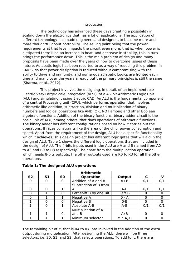
design of ALU. Table 1 shows the different logic operations that are included in
the design of ALU. The 4-bits inputs used in the ALU are A and B named from A0
to A3 and B0 to B3 respectively. The apart from the multiplication operation,
which needs 8-bits outputs, the other outputs used are R0 to R3 for all the other
operations.
Table 1: The designed ALU operations
S2 S1 S0
Arithmetic
Operation Output C V
0 0 0 Addition of A and B A+B 0/1 0/1
0 0 1
Subtraction of B from
A A-B 0/1 0/1
0 1 0 Left shift B by one Bit Left B 0 0
0 1 1 Negative A 0 - A 0 0
1 0 0 Negative B 0-B 0 0
1 0 1 Absolute A-B |A-B| 0/1 0/1
1 1 0
Multiplication of A
and B AxB 0 0
1 1 1 Minimum selector Min A, B 0 0
The remaining bit of it, that is R4 to R7, are involved in the addition of the extra
output during multiplication. After designing the ALU, there will be three
selectors, i.e. S0, S1, and S2, that selects operations. To add to it, there are
Designing and Simulating a 4-bit ALU using Electric CAD_2

End of preview

Want to access all the pages? Upload your documents or become a member.

Related Documents
DIGITAL LOGIC QUESTION ONE 4 BIT ADDER-SUBTRACTOR
|10
|942
|259

Computer Organisation and Design - Doc
|14
|1400
|306

4CS015 Fundamentals of Computing - Assignment
|4
|606
|1175

Communication Device Theory and Design
|12
|1044
|14

Digital Electronics Laboratory Assignment
|19
|1972
|114

Benefits of Using Binary Arithmetic System
|10
|2213
|290