Finite Element Analysis of Truck Axle
Added on 2023-03-17
34 Pages7888 Words37 Views
ABSTRACT.
This report aims at describing the method of Finite element analysis (FEA) used to
simulate an axle of a truck. The axle is where all the loads lie upon. An axle is
similar to a shaft only that it does not rotate. Materials that makes these parts are
as a result very strong. In this report, the origin of forces acting on the chasses the
type of forces acting on a truck chassis and their points of action on the chasses are
explained. To have a good view and encounter with FEA elements, both axles of a
truck were designed on a CAD software. The Material properties of the axles such as
Youngs modulus, tensile strength, Poisson’s ratio and yield strength were read from
the mass properties of the material. With these parameters and constants, the
loads, shear force diagrams, bending moment diagram, deflection diagrams and the
maximum shear and bending stress were calculated.
The focus of this task is to determine the locations of the maximum shear stress,
deflection and to determine the best factor of safety. In engineering design FEA is a
very important tool in calculation of reactions, stresses, strains and deformations,
which might be very difficult to solve by manually. You realize that most stresses
are caused by combined forces and the geometries are irregular in shape thus
making it hard for use of hand calculations. This report aims at showing how this
problem can be tackled with the help of FEA tools such as ANSYS. With these design
utilities, much of the design work is simplified and the designer is left with just a few
things to improve on. As a result, manufacturing is eased and faster design
processes are possible. They have enabled engineers and designers to have a look
at the behavior of the parts, product and designs ages before it is actually
produced.
1. INTRODUCTION
Axles are non-rotating parts used to transmit torque to rotating elements. It
supports the chasses to the wheel and also the suspension system. Transportation
industry assumes a noteworthy job in the economy of present day industrialized
and creating nations. The aggregate and relative volume of merchandise continued
overwhelming trucks is significantly expanding. The axle structure should securely
bolster the heaviness of the vehicle segments and transmit loads that outcome
from longitudinal, parallel, and vertical increasing speeds that are knowledgeable
about a hustling situation without disappointment.
The truck axle assumes a significant job in the usefulness of the vehicle. For the
most part, truck is an overwhelming engine vehicle intended for carrying heavy
loads. The significant concentration in the fabrication firms is structure of trucks.
Utilizing bigger quality metal steels than the customary trucks and are conceivable
with comparing increment in load limit. The undercarriage of trucks which is the
foundation of vehicles that coordinates the fundamental segment of the
frameworks, for example, the axles, suspension, control train and trailer and so on.
1
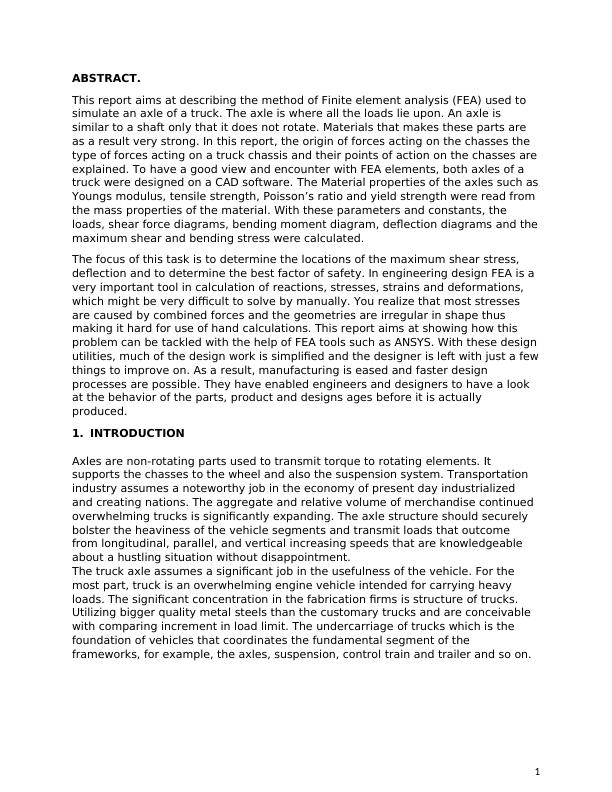
(Parts of An axle)
Axles can be categorized according to the working conditions and the position
they are located. According to the location they are located, axles can be
grouped to front and rear axle. According to the working conditions they can be
grouped into dead axle and live axle.
Live axle transmit power from the differentials to the wheels. Dead axles also
called lazy axles is actually a drivetrain and does not transmit the power. They
are used for mounting the bearings gears but in vehicles wheels. (Rahman)
The common forces that acts on an axle are side trust, drive thrust, the weight
of the body plus the weight of the cargo and the overloads and the torque
reaction. Short duration loads such as when crossing a bump or even a broken
patch. Axles usually experience momentary duration loads (turning effect of a
force) when negotiating corners and curves. Once you apply brakes the chasses
also experience inertia too the same as the other body parts. The weight of the
engine, body and other loads can be termed as static loads because they do not
move. The chasses is under this loading all the time.
FEA has turned out to be prevalent in the structure designing field. Today it is
viewed as one of the pivotal and real plan devices. It has aided the arrangement
of a lot of answers for the undeniable and confused issues in the building field. It
is thusly an indispensable piece of the in the plan of the car parts or segments,
common development and in the modern applications is essentially used to
foresee the different static and the dynamic basic reactions. The automotice
organizations use FEA to anticipate the pressure, disfigurements, strain and
disappointment of various parts. This procedure diminishes the requirement for
extravagant examinations that are known to include and takes into account the
enhancement of the parts under test before they are at long last exposed to the
pragmatic utilization of before they are constructed.
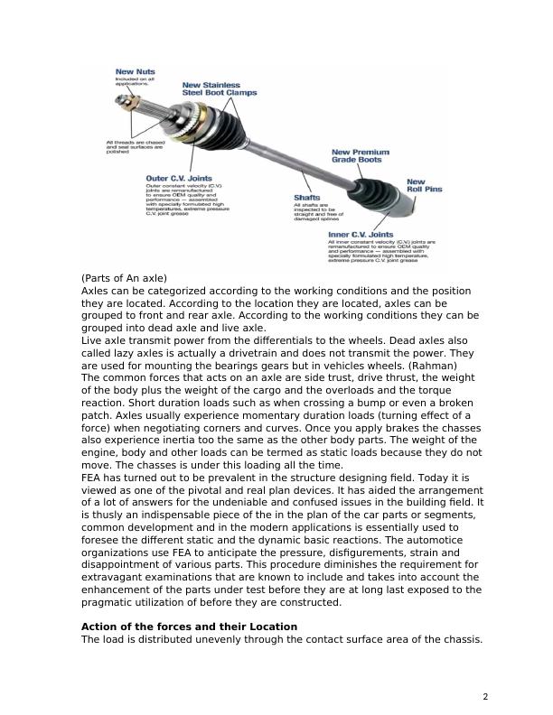
Action of the forces and their Location
The load is distributed unevenly through the contact surface area of the chassis.
2
Axles can be categorized according to the working conditions and the position
they are located. According to the location they are located, axles can be
grouped to front and rear axle. According to the working conditions they can be
grouped into dead axle and live axle.
Live axle transmit power from the differentials to the wheels. Dead axles also
called lazy axles is actually a drivetrain and does not transmit the power. They
are used for mounting the bearings gears but in vehicles wheels. (Rahman)
The common forces that acts on an axle are side trust, drive thrust, the weight
of the body plus the weight of the cargo and the overloads and the torque
reaction. Short duration loads such as when crossing a bump or even a broken
patch. Axles usually experience momentary duration loads (turning effect of a
force) when negotiating corners and curves. Once you apply brakes the chasses
also experience inertia too the same as the other body parts. The weight of the
engine, body and other loads can be termed as static loads because they do not
move. The chasses is under this loading all the time.
FEA has turned out to be prevalent in the structure designing field. Today it is
viewed as one of the pivotal and real plan devices. It has aided the arrangement
of a lot of answers for the undeniable and confused issues in the building field. It
is thusly an indispensable piece of the in the plan of the car parts or segments,
common development and in the modern applications is essentially used to
foresee the different static and the dynamic basic reactions. The automotice
organizations use FEA to anticipate the pressure, disfigurements, strain and
disappointment of various parts. This procedure diminishes the requirement for
extravagant examinations that are known to include and takes into account the
enhancement of the parts under test before they are at long last exposed to the
pragmatic utilization of before they are constructed.
Action of the forces and their Location
The load is distributed unevenly through the contact surface area of the chassis.
2
Origin of forces
Forces following up on the suspension are because of the vehicles weight and
the chassis, that brings about vertical contorting and deflection the chassis
body. When the truck goes over a rough road there is longitudinal torsion due to
twisting of one wheel that is lifted with various wheels touching the road. These
Forces are as a result of road bumps, sideway drag, cornering forces while taking
corners, which result in level bowing to the sides. Forces are likewise as a result
of wheel influence by road hindrances may cause that particular wheel be left
blocked as the other will when all is said in move forward, causing a
parallelogram shape deformation at the edges. Motor torque and braking torque
as a result tend to curve the axle in the vertical plane. Sudden forces loads or
impact on the axle, which may result in generally breakdown. Dynamic loadings
are as a result of forces caused when the vehicle hit the bumps through shock
absorbers (such as leaf springs and coil springs), aerodynamic forces due to the
lift and drag forces caused by the air hit by the truck.
loaded truck under various conditions
All the weight of the chassis plus the overload and the cargo carried by the tuck
acts on the axle. The axle is not connected to the chassis directly but it is
connected to a system of shock absorbers. Absorbers prevent damage on the
axle and chassis. By so doing, the chassis and the axle do not hit each other
during a time of impact.
On the front axle (lazy axle) the chassis is normally connected to the axle using
U -bolts. Four U-bolts are used to fasten the chassis onto the axle. This is
between the two ends of the axle but not too close (just near the wheels). It is
desired to have the distance between the two U bolts as big as possible for
stability. Putting them near the wheels (fixed support) also minimizes the
deflections on the axles.
3

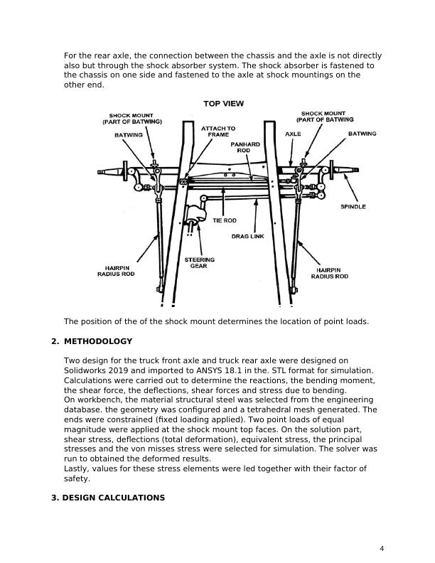
For the rear axle, the connection between the chassis and the axle is not directly
also but through the shock absorber system. The shock absorber is fastened to
the chassis on one side and fastened to the axle at shock mountings on the
other end.
The position of the of the shock mount determines the location of point loads.
2. METHODOLOGY
Two design for the truck front axle and truck rear axle were designed on
Solidworks 2019 and imported to ANSYS 18.1 in the. STL format for simulation.
Calculations were carried out to determine the reactions, the bending moment,
the shear force, the deflections, shear forces and stress due to bending.
On workbench, the material structural steel was selected from the engineering
database. the geometry was configured and a tetrahedral mesh generated. The
ends were constrained (fixed loading applied). Two point loads of equal
magnitude were applied at the shock mount top faces. On the solution part,
shear stress, deflections (total deformation), equivalent stress, the principal
stresses and the von misses stress were selected for simulation. The solver was
run to obtained the deformed results.
Lastly, values for these stress elements were led together with their factor of
safety.
3. DESIGN CALCULATIONS
4
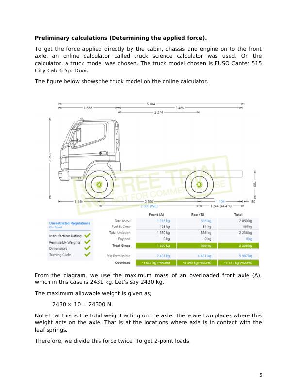
Preliminary calculations (Determining the applied force).
To get the force applied directly by the cabin, chassis and engine on to the front
axle, an online calculator called truck science calculator was used. On the
calculator, a truck model was chosen. The truck model chosen is FUSO Canter 515
City Cab 6 Sp. Duoi.
The figure below shows the truck model on the online calculator.
From the diagram, we use the maximum mass of an overloaded front axle (A),
which in this case is 2431 kg. Let’s say 2430 kg.
The maximum allowable weight is given as;
2430 × 10 = 24300 N.
Note that this is the total weight acting on the axle. There are two places where this
weight acts on the axle. That is at the locations where axle is in contact with the
leaf springs.
Therefore, we divide this force twice. To get 2-point loads.
5
P1 = P2 = 24300
2 = 12150 N
The maximum mass of an overloaded front axle (B), which in this case is 4481 kg.
Let’s say 4480 kg.
The maximum allowable weight is given as;
4480 × 10 = 44800 N.
Note that this is the total weight acting on the axle. There are two places where this
weight acts on the axle. That is at the locations where axle is in contact with the
leaf springs.
Therefore, we divide this force twice. To get 2 point loads.
P1 = P2 = 44800
2 = 22400 N
A) FRONT AXLE
Assumptions.
6
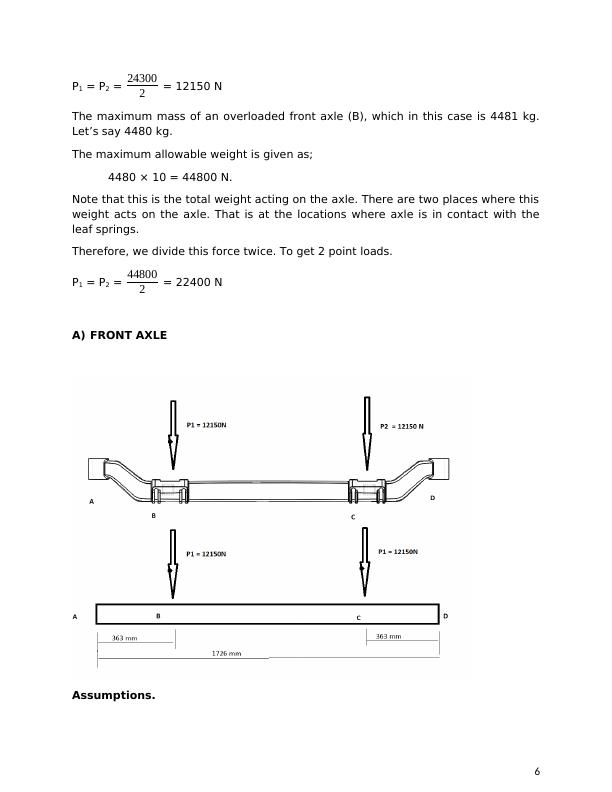
For the basis of calculation, the following assumptions were made.
i) The axle is straight as shown on the second diagram and have a uniform
cross section.
ii) The axle cross-section is rectangular in shape with width 104 mm and height
of 110 mm.
iii) The weight of the axle is uniformly distributed along its length.
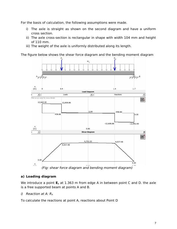
The figure below shows the shear force diagram and the bending moment diagram
(Fig: shear force diagram and bending moment diagram)
a) Loading diagram
We introduce a point E, at 1.363 m from edge A in between point C and D. the axle
is a free supported beam at points A and B.
i) Reaction at A: RA
To calculate the reactions at point A, reactions about Point D
7
i) The axle is straight as shown on the second diagram and have a uniform
cross section.
ii) The axle cross-section is rectangular in shape with width 104 mm and height
of 110 mm.
iii) The weight of the axle is uniformly distributed along its length.
The figure below shows the shear force diagram and the bending moment diagram
(Fig: shear force diagram and bending moment diagram)
a) Loading diagram
We introduce a point E, at 1.363 m from edge A in between point C and D. the axle
is a free supported beam at points A and B.
i) Reaction at A: RA
To calculate the reactions at point A, reactions about Point D
7
∑ MyD = 0 + (assuming positive sign convention).
0 = (-RA × 1.726) + (1584 × 0.863) + (12150 × 1.363) + (12150 ×
0.363)
1.726RA = 1366.992 + 1650.45 + 4410.45
1.726RA = 22337.892
RA = 12942 N
i) Reaction at D: RD
To calculate the reactions at point D, reactions about Point A
∑ MyA = 0 (assuming positive sign convention).
0 = (RD × 1.726) + (-12150 × 1.363) + (1584 × 0.863) + (-12150 ×
0.363)
1.726RD = 22337.892
1.726RD = 12942 N
b) Shear force diagram, V
VA- = 0 kN
VA+ = VA- + 12942 = 12942 N
VB- = VA+ - area of ω- diagram]BA = 12942 – (917.7289 × 0.363) = 12608.86 N
VB+ = VB- + P1 = 12608.86 – 12150 = 458.86 N
VC- = VB+ - area of ω- diagram]CA = 458.86 – (917.7289 × 1) = - 458.56 N
VC+ = VC- + PC = - 458.56 +-12150 = 12608.86 N
VD- = VC+ - area of ω- diagram]AF = -12608 – (917.7289 × 0.363) = -12942.0 N
VD+ = VD- + RD = -12942.0 3 +12942 = 0 N
c) Bending Force Diagram
MA = 0 (No couple at the point)
MB = MA + area of v-diagram]BA
= 0 + ( 12608.86 ×0.363) – ( 1
2× 0.363 × 0.5)
= 4637.48 Nm
8
End of preview
Want to access all the pages? Upload your documents or become a member.
Related Documents
Finite Element Analysis of Truck Axlelg...
|67
|12457
|1
Complete Beam Design with MDSolids Verificationlg...
|19
|2354
|392
Euler-Bernoulli Beam Theory in a Simply Supported Beam without Reinforcementlg...
|12
|2463
|60
Complete Beam Design with MDSolids Verificationlg...
|14
|621
|245
Mechanical Systems: Analysis of Engine Crane, Chair Structure, Industrial Robot, Ski, Sign Post and Diving Boardlg...
|20
|1792
|324
Mechanics of Harbour Bridge Sydneylg...
|21
|4345
|359