Analysis of Hydraulic Structures and Environmental Impact
VerifiedAdded on 2021/04/21
|27
|11617
|104
AI Summary
This document presents a collection of research papers and studies on hydraulic structures, including dams, tunnels, and water management systems. The papers cover topics such as design, construction, and environmental impact assessment of these structures. Case studies from around the world are included to provide practical examples of hydraulic structure implementation and their effects on the environment.
Contribute Materials
Your contribution can guide someone’s learning journey. Share your
documents today.
Running head: ADVANCED CIVIL ENGINEERING
B5U37 Advanced Civil Engineering
Student Name:
University Name:
Lecturer: Peter Tse / Dr. Peter Kwan
B5U37 Advanced Civil Engineering
Student Name:
University Name:
Lecturer: Peter Tse / Dr. Peter Kwan
Secure Best Marks with AI Grader
Need help grading? Try our AI Grader for instant feedback on your assignments.
1ADVANCED CIVIL ENGINEERING
Table of Contents
Task 1....................................................................................................................................................2
Task 1.1 – Three construction methods for tunneling......................................................................2
Task 1.2 – Appropriate methods used in tunnels and shafts.............................................................3
Task 2....................................................................................................................................................7
Task 2.1 – Three construction methods for hydraulic structures......................................................7
Task 2.2 – Appropriate methods used in hydraulic structures..........................................................8
Task 3..................................................................................................................................................10
Task 3.1 – Three construction methods for marine works.............................................................10
Task 3.2 – Appropriate methods used in marine works.................................................................11
Task 4..................................................................................................................................................14
Task 4.1 – Three construction methods for highway and railway works.......................................14
Task 4.2 – Appropriate methods used in highway and railway works...........................................15
Task 5..................................................................................................................................................16
Task 5.1 – Appropriate solutions for slope stabilization................................................................16
Task 5.2 – Detailed resource plan for civil engineering activity....................................................19
References...........................................................................................................................................22
List of Figures
Figure 1: Cut and Cover tunneling method..........................................................................................4
Figure 2: Drill and Blast tunneling method..........................................................................................5
Figure 3: Drill and Blast tunneling method..........................................................................................6
Figure 4: Type of Dam (Earth Fill).......................................................................................................9
Figure 5: Type of Dam (Gravity)..........................................................................................................9
Figure 6: Type of Dam (Arch)............................................................................................................10
Figure 7: Caissons for marine construction works.............................................................................12
Figure 8: Suctions dredgers for marine construction works...............................................................13
Figure 9: Immersed-Tube tunneling method (Fehmarnbelt Tunnel)..................................................13
Figure 10: Slope Stabilization calculation..........................................................................................17
2ADVANCED CIVIL ENGINEERING
Task 1
Task 1.1 – Three construction methods for tunneling
This section depicts the methods that are used for construction of tunnels and can be
possibly utilized in various other projects. The various techniques of tunneling are cut and cover,
drill and blast along with bored tunneling. The three mentioned techniques are the most common
type of construction methods used for tunneling. Although, the methods are used for construction of
small tunnels, their applications is wide. The detailed discussion on the construction methods for
tunneling are as below:
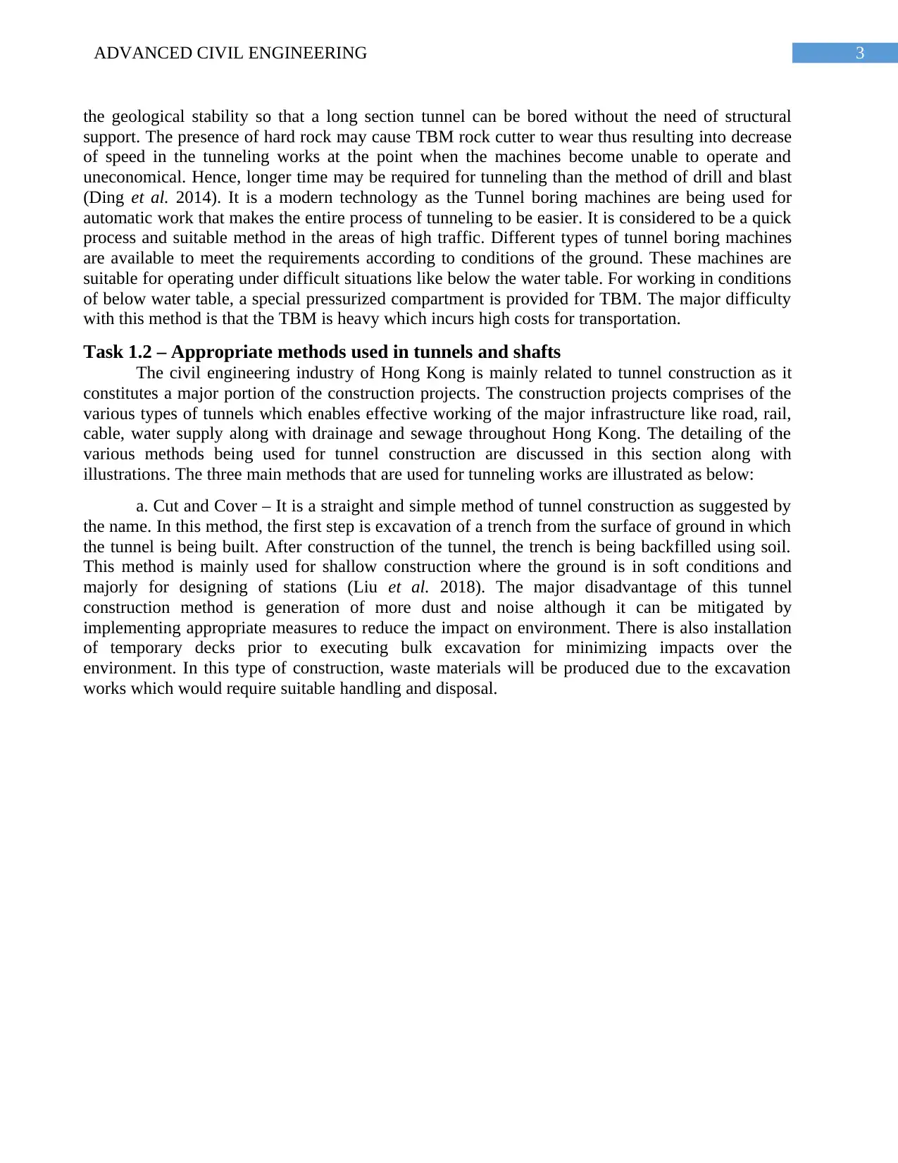
a. Cut and Cover – This method is the most common of all techniques and is considered
suitable to construct shallow tunnels. In this method, there is scope of accommodating changes in
the width of tunnels as well as non-uniform shapes (Wu et al. 2015). This method is used to
construct underground stations. There is a requirement to carry out several overlapping works while
using this construction method for tunneling. The three integral parts of this method are trench
excavation, construction of tunnel and covering the excavated tunnels with soil.
The works conducted in this type of construction is similar to that of other construction
works but the level of excavation is deeper. Bulk excavation is undertaken beneath a road deck for
minimizing the disruption of traffic along with impact on the environment related to emission of
dust and noise as well as visual impact (Zhang et al. 2015). The cutting in this method can be
executed by using two methods. One method is bottom up where a tunnel is dug under the surface
with the help of ground support. The other method is top-down where construction of side support
wall is done at first using slurry walling method or even contiguous bored pilling. The excavation is
carried out where the roof is located at the top of walls and finally the construction of base slab is
carried out. This method is used mainly for constructing underground metro railway stations.
b. Drill and Blast – In this method, explosives are used for construction of tunnels. For
drilling blast holes on the surface of tunnel to be constructed there is a need of drilling rigs. The
drilling rigs will be used for blasting holes to a specified depth (Bai, Yang and Jiang 2014). The
blast holes are then placed with explosives as well as timed detonators also known as delay
detonators. After execution of the blasting, transportation of waste rocks along with soils is carried
out before carrying out further blasting works.
In almost every construction of tunnels in rock, there is involvement of ground which lies
between the hard rock and soft ground. Therefore, adequate measures for structural support is
required to adopt this method for constructing tunnels. In this method, there is occurrence of higher
vibration levels but for a lesser duration. There is a need for temporary magazine site so that
explosives can be stored overnight. The pattern of drilling ensures that there is proper distribution of
explosives within the rock to achieve the blasting results as desired (Li, Zhao and Zhou 2016). The
main concern of designing the drilling patterns is to ensure drilled holes are accurately placed to
provide an optimum solution. The design supports suitable charging and blasting for producing
smooth walls, roof and floor of the tunnel.
c. Bored Tunneling – This method is often used in the excavation of long tunnels. In an
effective bored tunneling method, there is a requirement to select suitable equipment for various
mass of rocks and even geological conditions. This method may prove to be suitable for excavation
of tunnels containing competent rocks (Antucheviciene et al. 2015). Those rocks offer support and
Task 1
Task 1.1 – Three construction methods for tunneling
This section depicts the methods that are used for construction of tunnels and can be
possibly utilized in various other projects. The various techniques of tunneling are cut and cover,
drill and blast along with bored tunneling. The three mentioned techniques are the most common
type of construction methods used for tunneling. Although, the methods are used for construction of
small tunnels, their applications is wide. The detailed discussion on the construction methods for
tunneling are as below:
a. Cut and Cover – This method is the most common of all techniques and is considered
suitable to construct shallow tunnels. In this method, there is scope of accommodating changes in
the width of tunnels as well as non-uniform shapes (Wu et al. 2015). This method is used to
construct underground stations. There is a requirement to carry out several overlapping works while
using this construction method for tunneling. The three integral parts of this method are trench
excavation, construction of tunnel and covering the excavated tunnels with soil.
The works conducted in this type of construction is similar to that of other construction
works but the level of excavation is deeper. Bulk excavation is undertaken beneath a road deck for
minimizing the disruption of traffic along with impact on the environment related to emission of
dust and noise as well as visual impact (Zhang et al. 2015). The cutting in this method can be
executed by using two methods. One method is bottom up where a tunnel is dug under the surface
with the help of ground support. The other method is top-down where construction of side support
wall is done at first using slurry walling method or even contiguous bored pilling. The excavation is
carried out where the roof is located at the top of walls and finally the construction of base slab is
carried out. This method is used mainly for constructing underground metro railway stations.
b. Drill and Blast – In this method, explosives are used for construction of tunnels. For
drilling blast holes on the surface of tunnel to be constructed there is a need of drilling rigs. The
drilling rigs will be used for blasting holes to a specified depth (Bai, Yang and Jiang 2014). The
blast holes are then placed with explosives as well as timed detonators also known as delay
detonators. After execution of the blasting, transportation of waste rocks along with soils is carried
out before carrying out further blasting works.
In almost every construction of tunnels in rock, there is involvement of ground which lies
between the hard rock and soft ground. Therefore, adequate measures for structural support is
required to adopt this method for constructing tunnels. In this method, there is occurrence of higher
vibration levels but for a lesser duration. There is a need for temporary magazine site so that
explosives can be stored overnight. The pattern of drilling ensures that there is proper distribution of
explosives within the rock to achieve the blasting results as desired (Li, Zhao and Zhou 2016). The
main concern of designing the drilling patterns is to ensure drilled holes are accurately placed to
provide an optimum solution. The design supports suitable charging and blasting for producing
smooth walls, roof and floor of the tunnel.
c. Bored Tunneling – This method is often used in the excavation of long tunnels. In an
effective bored tunneling method, there is a requirement to select suitable equipment for various
mass of rocks and even geological conditions. This method may prove to be suitable for excavation
of tunnels containing competent rocks (Antucheviciene et al. 2015). Those rocks offer support and
3ADVANCED CIVIL ENGINEERING
the geological stability so that a long section tunnel can be bored without the need of structural
support. The presence of hard rock may cause TBM rock cutter to wear thus resulting into decrease
of speed in the tunneling works at the point when the machines become unable to operate and
uneconomical. Hence, longer time may be required for tunneling than the method of drill and blast
(Ding et al. 2014). It is a modern technology as the Tunnel boring machines are being used for
automatic work that makes the entire process of tunneling to be easier. It is considered to be a quick
process and suitable method in the areas of high traffic. Different types of tunnel boring machines
are available to meet the requirements according to conditions of the ground. These machines are
suitable for operating under difficult situations like below the water table. For working in conditions
of below water table, a special pressurized compartment is provided for TBM. The major difficulty
with this method is that the TBM is heavy which incurs high costs for transportation.
Task 1.2 – Appropriate methods used in tunnels and shafts
The civil engineering industry of Hong Kong is mainly related to tunnel construction as it
constitutes a major portion of the construction projects. The construction projects comprises of the
various types of tunnels which enables effective working of the major infrastructure like road, rail,
cable, water supply along with drainage and sewage throughout Hong Kong. The detailing of the
various methods being used for tunnel construction are discussed in this section along with
illustrations. The three main methods that are used for tunneling works are illustrated as below:
a. Cut and Cover – It is a straight and simple method of tunnel construction as suggested by
the name. In this method, the first step is excavation of a trench from the surface of ground in which
the tunnel is being built. After construction of the tunnel, the trench is being backfilled using soil.
This method is mainly used for shallow construction where the ground is in soft conditions and
majorly for designing of stations (Liu et al. 2018). The major disadvantage of this tunnel
construction method is generation of more dust and noise although it can be mitigated by
implementing appropriate measures to reduce the impact on environment. There is also installation
of temporary decks prior to executing bulk excavation for minimizing impacts over the
environment. In this type of construction, waste materials will be produced due to the excavation
works which would require suitable handling and disposal.
Secure Best Marks with AI Grader
Need help grading? Try our AI Grader for instant feedback on your assignments.
4ADVANCED CIVIL ENGINEERING
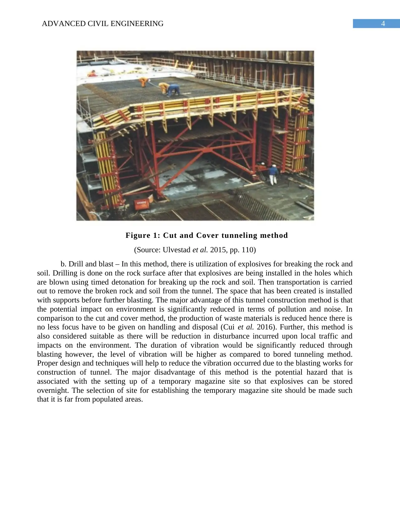
Figure 1: Cut and Cover tunneling method
(Source: Ulvestad et al. 2015, pp. 110)
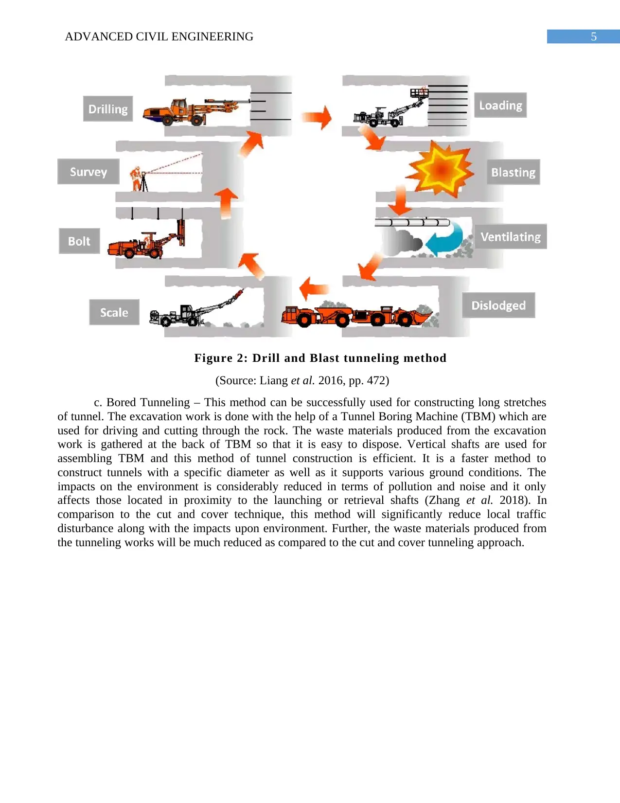
b. Drill and blast – In this method, there is utilization of explosives for breaking the rock and
soil. Drilling is done on the rock surface after that explosives are being installed in the holes which
are blown using timed detonation for breaking up the rock and soil. Then transportation is carried
out to remove the broken rock and soil from the tunnel. The space that has been created is installed
with supports before further blasting. The major advantage of this tunnel construction method is that
the potential impact on environment is significantly reduced in terms of pollution and noise. In
comparison to the cut and cover method, the production of waste materials is reduced hence there is
no less focus have to be given on handling and disposal (Cui et al. 2016). Further, this method is
also considered suitable as there will be reduction in disturbance incurred upon local traffic and
impacts on the environment. The duration of vibration would be significantly reduced through
blasting however, the level of vibration will be higher as compared to bored tunneling method.
Proper design and techniques will help to reduce the vibration occurred due to the blasting works for
construction of tunnel. The major disadvantage of this method is the potential hazard that is
associated with the setting up of a temporary magazine site so that explosives can be stored
overnight. The selection of site for establishing the temporary magazine site should be made such
that it is far from populated areas.
Figure 1: Cut and Cover tunneling method
(Source: Ulvestad et al. 2015, pp. 110)
b. Drill and blast – In this method, there is utilization of explosives for breaking the rock and
soil. Drilling is done on the rock surface after that explosives are being installed in the holes which
are blown using timed detonation for breaking up the rock and soil. Then transportation is carried
out to remove the broken rock and soil from the tunnel. The space that has been created is installed
with supports before further blasting. The major advantage of this tunnel construction method is that
the potential impact on environment is significantly reduced in terms of pollution and noise. In
comparison to the cut and cover method, the production of waste materials is reduced hence there is
no less focus have to be given on handling and disposal (Cui et al. 2016). Further, this method is
also considered suitable as there will be reduction in disturbance incurred upon local traffic and
impacts on the environment. The duration of vibration would be significantly reduced through
blasting however, the level of vibration will be higher as compared to bored tunneling method.
Proper design and techniques will help to reduce the vibration occurred due to the blasting works for
construction of tunnel. The major disadvantage of this method is the potential hazard that is
associated with the setting up of a temporary magazine site so that explosives can be stored
overnight. The selection of site for establishing the temporary magazine site should be made such
that it is far from populated areas.
5ADVANCED CIVIL ENGINEERING
Figure 2: Drill and Blast tunneling method
(Source: Liang et al. 2016, pp. 472)
c. Bored Tunneling – This method can be successfully used for constructing long stretches
of tunnel. The excavation work is done with the help of a Tunnel Boring Machine (TBM) which are
used for driving and cutting through the rock. The waste materials produced from the excavation
work is gathered at the back of TBM so that it is easy to dispose. Vertical shafts are used for
assembling TBM and this method of tunnel construction is efficient. It is a faster method to
construct tunnels with a specific diameter as well as it supports various ground conditions. The
impacts on the environment is considerably reduced in terms of pollution and noise and it only
affects those located in proximity to the launching or retrieval shafts (Zhang et al. 2018). In
comparison to the cut and cover technique, this method will significantly reduce local traffic
disturbance along with the impacts upon environment. Further, the waste materials produced from
the tunneling works will be much reduced as compared to the cut and cover tunneling approach.
6ADVANCED CIVIL ENGINEERING
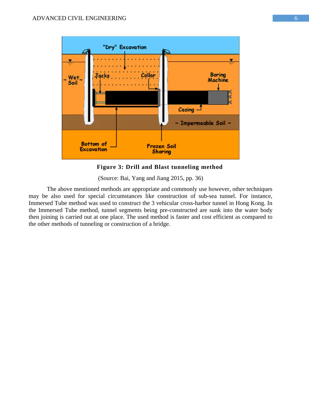
Figure 3: Drill and Blast tunneling method
(Source: Bai, Yang and Jiang 2015, pp. 36)
The above mentioned methods are appropriate and commonly use however, other techniques
may be also used for special circumstances like construction of sub-sea tunnel. For instance,
Immersed Tube method was used to construct the 3 vehicular cross-harbor tunnel in Hong Kong. In
the Immersed Tube method, tunnel segments being pre-constructed are sunk into the water body
then joining is carried out at one place. The used method is faster and cost efficient as compared to
the other methods of tunneling or construction of a bridge.
Paraphrase This Document
Need a fresh take? Get an instant paraphrase of this document with our AI Paraphraser
7ADVANCED CIVIL ENGINEERING
Task 2
Task 2.1 – Three construction methods for hydraulic structures
The auxiliary execution is generally surveyed by methods for adjustment models in view of
physical understanding and observational information. Because of admired displaying, inalienable
physical vulnerabilities, and lacking or inadequate information, these models themselves and the
parameters entering the models are dubious. Enhancement procedures assume a key part in basic
outline (Chen and Chen 2016). The very motivation behind which is to locate the most ideal way
with the goal that a creator or a chief can get a greatest advantage from the accessible assets.
Computer Aided Design (CAD) is a thorough utilization of PC framework to aid the creation,
change, investigation, or enhancement, of an outline. Computer aided design may upgrade the
profitability of the planner, enhance the nature of the outline, quicken the interchanges through
documentation, and make a database for assembling and administration. A pressure driven structure
is a structure submerged or in part submerged in anyone of water, which upsets the common stream
of water. They can be utilized to occupy, upset or totally stop the stream. A case of a pressure driven
structure would be a dam, which moderates the ordinary stream rate of waterway keeping in mind
the end goal to control turbines (Shi and Wang 2015). A pressure driven structure can be worked in
streams, an ocean, or anyone of water where there is a requirement for an adjustment in the regular
stream of water.
Earth Dam: Some writing may refer to any dam developed of exhumed earth materials, for
example, sand, sand rock or soils as a fill dam. As the name infers, material is filled or set to make
mass with slopeing sides. Upstream and downstream dam appearances of dike dams are both
inclining. Minor departure from this idea use diverse materials that may be shake, earth, moved
earth or using pressurized water put fill (Al-Juboori and Datta 2018). All require "fixing" against
leakage with an impenetrable area, zone or center.
Gravity Dam: A dam built of cement or brick work (quarried shake) units that depends upon
its weight for strength against upsetting or sliding. Varieties of present day configuration may
incorporate curve, bend or cell (empty) styles.
Arch Dam: A solid or brick work dam that is bended in design in order to transmit the
significant piece of the water load to the projections. Minor departure from this plan more often than
not include shape and load bearing component adjustments.
Notwithstanding dam compose and style, outline contemplations must record for stack
conditions amid activity, most extreme surge, wind and wave, ice, seiche and tremor that may
demonstration to disintegrate, rupture, upset or slide the dam. Broad investigative examinations are
important in picking a dam site (Ulises et al. 2017). Ground planning may require alteration of the
profile of hidden earth, shake or both to balance out the establishment. Solidness, bearing quality
and water snugness are essential criteria for establishment and projection dividers of the proposed
site.
Visual and instrumentation checking of the establishment and structure is important to
evaluate the proceeded with uprightness of the venture. Such conditions as inspire, settlement,
leakage, waste and development should be observed and assessed in a proceeding with program.
The motivation behind instrumentation is to outfit information that can be utilized to decide whether
the structure is keeping up its trustworthiness and soundness as planned, and to give a persistent
8ADVANCED CIVIL ENGINEERING
observation of the structure to caution of advancements which imperil its security (Pardo-Bosch and
Aguado 2015).
Dams built out of brick work or cement and which depend exclusively on its self-weight for
soundness fall under the terminology of gravity dams. It is critical to take note of that, it is not only
adequate to outline a solid dam structure, however it is similarly essential to check the establishment
too for auxiliary honesty. For solid dams, the pressure created at the intersection of the base turns
out to be very high, which the establishment needs to stand up to. Normally solid gravity dams are
built over a stream by uncovering without end the free overburden till firm shake is experienced
which is considered as the genuine establishment (Tanchev 2014). By and by not all stones are of a
similar quality; they fluctuate with various topographical materials and the procedure by which they
have been framed throughout the years.
Task 2.2 – Appropriate methods used in hydraulic structures
Hydraulic structures are anything that can be utilized to occupy, limit, stop, or generally deal
with the characteristic stream of water. They can be produced using materials running from vast
shake and cement to cloud things, for example, wooden timbers or tree trunks. Dam, for example, is
a kind of pressure driven structure used to hold water in a store as potential vitality, similarly as a
weir is a sort of water driven structure which can be utilized to pool water for water system, build up
control of the bed (review control) or, as another imaginative strategy, to occupy stream far from
disintegrating banks or into redirection channels for surge control. A dam is a pressure driven
structure of genuinely impenetrable material worked over a stream to make a repository on its
upstream side for appropriating water for different purposes (Bazhenov, Bulgakov and Alexandrova
2016). These reasons might be Irrigation, Hydro-control, Water-supply, Flood Control, Navigation,
Fishing and Recreation. Dams might be worked to meet the one of the above purposes or they might
be built satisfying more than one.
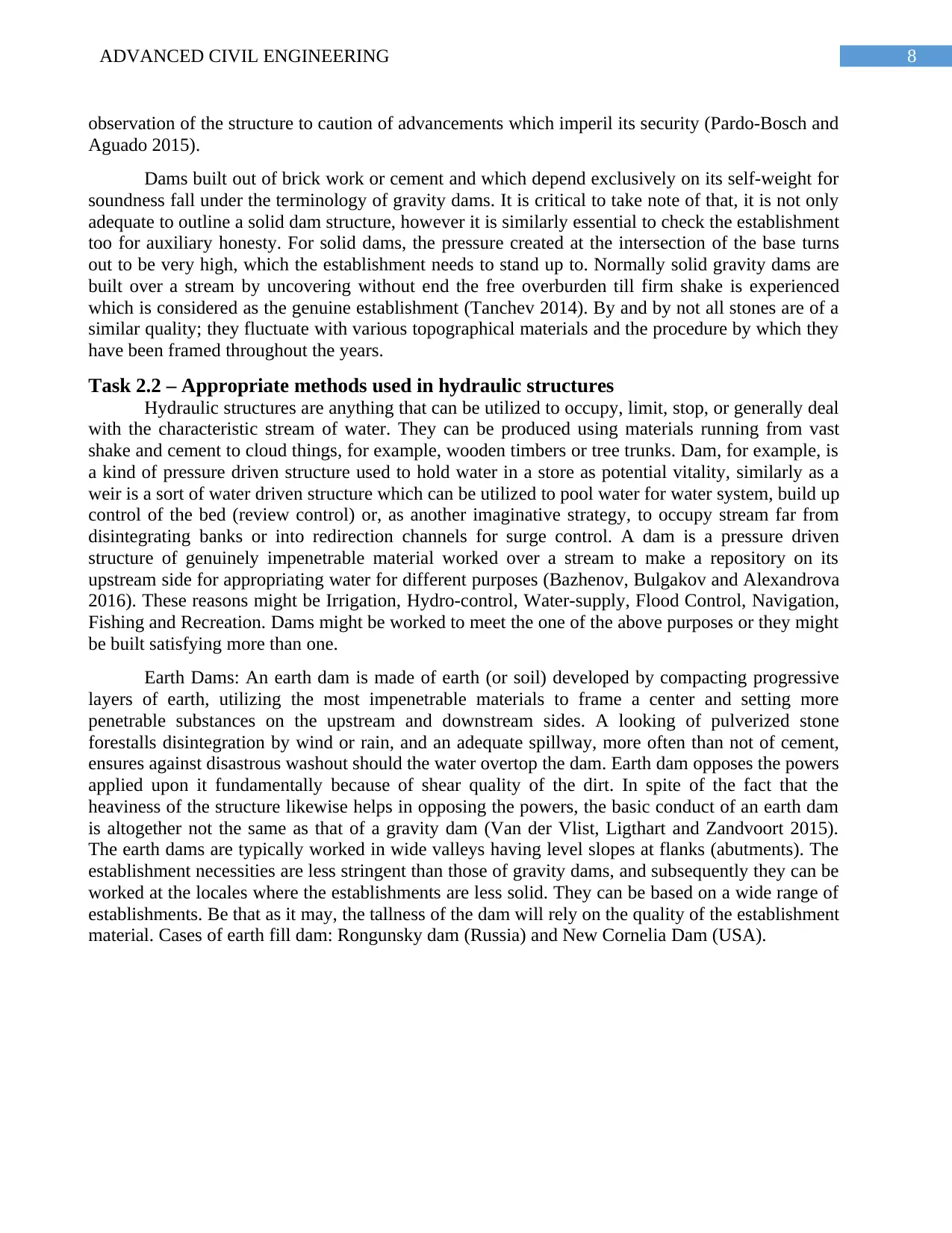
Earth Dams: An earth dam is made of earth (or soil) developed by compacting progressive
layers of earth, utilizing the most impenetrable materials to frame a center and setting more
penetrable substances on the upstream and downstream sides. A looking of pulverized stone
forestalls disintegration by wind or rain, and an adequate spillway, more often than not of cement,
ensures against disastrous washout should the water overtop the dam. Earth dam opposes the powers
applied upon it fundamentally because of shear quality of the dirt. In spite of the fact that the
heaviness of the structure likewise helps in opposing the powers, the basic conduct of an earth dam
is altogether not the same as that of a gravity dam (Van der Vlist, Ligthart and Zandvoort 2015).
The earth dams are typically worked in wide valleys having level slopes at flanks (abutments). The
establishment necessities are less stringent than those of gravity dams, and subsequently they can be
worked at the locales where the establishments are less solid. They can be based on a wide range of
establishments. Be that as it may, the tallness of the dam will rely on the quality of the establishment
material. Cases of earth fill dam: Rongunsky dam (Russia) and New Cornelia Dam (USA).
observation of the structure to caution of advancements which imperil its security (Pardo-Bosch and
Aguado 2015).
Dams built out of brick work or cement and which depend exclusively on its self-weight for
soundness fall under the terminology of gravity dams. It is critical to take note of that, it is not only
adequate to outline a solid dam structure, however it is similarly essential to check the establishment
too for auxiliary honesty. For solid dams, the pressure created at the intersection of the base turns
out to be very high, which the establishment needs to stand up to. Normally solid gravity dams are
built over a stream by uncovering without end the free overburden till firm shake is experienced
which is considered as the genuine establishment (Tanchev 2014). By and by not all stones are of a
similar quality; they fluctuate with various topographical materials and the procedure by which they
have been framed throughout the years.
Task 2.2 – Appropriate methods used in hydraulic structures
Hydraulic structures are anything that can be utilized to occupy, limit, stop, or generally deal
with the characteristic stream of water. They can be produced using materials running from vast
shake and cement to cloud things, for example, wooden timbers or tree trunks. Dam, for example, is
a kind of pressure driven structure used to hold water in a store as potential vitality, similarly as a
weir is a sort of water driven structure which can be utilized to pool water for water system, build up
control of the bed (review control) or, as another imaginative strategy, to occupy stream far from
disintegrating banks or into redirection channels for surge control. A dam is a pressure driven
structure of genuinely impenetrable material worked over a stream to make a repository on its
upstream side for appropriating water for different purposes (Bazhenov, Bulgakov and Alexandrova
2016). These reasons might be Irrigation, Hydro-control, Water-supply, Flood Control, Navigation,
Fishing and Recreation. Dams might be worked to meet the one of the above purposes or they might
be built satisfying more than one.
Earth Dams: An earth dam is made of earth (or soil) developed by compacting progressive
layers of earth, utilizing the most impenetrable materials to frame a center and setting more
penetrable substances on the upstream and downstream sides. A looking of pulverized stone
forestalls disintegration by wind or rain, and an adequate spillway, more often than not of cement,
ensures against disastrous washout should the water overtop the dam. Earth dam opposes the powers
applied upon it fundamentally because of shear quality of the dirt. In spite of the fact that the
heaviness of the structure likewise helps in opposing the powers, the basic conduct of an earth dam
is altogether not the same as that of a gravity dam (Van der Vlist, Ligthart and Zandvoort 2015).
The earth dams are typically worked in wide valleys having level slopes at flanks (abutments). The
establishment necessities are less stringent than those of gravity dams, and subsequently they can be
worked at the locales where the establishments are less solid. They can be based on a wide range of
establishments. Be that as it may, the tallness of the dam will rely on the quality of the establishment
material. Cases of earth fill dam: Rongunsky dam (Russia) and New Cornelia Dam (USA).
9ADVANCED CIVIL ENGINEERING
Figure 4: Type of Dam (Earth Fill)
(Source: Balzannikov and Mikhasek 2014, pp. 185)
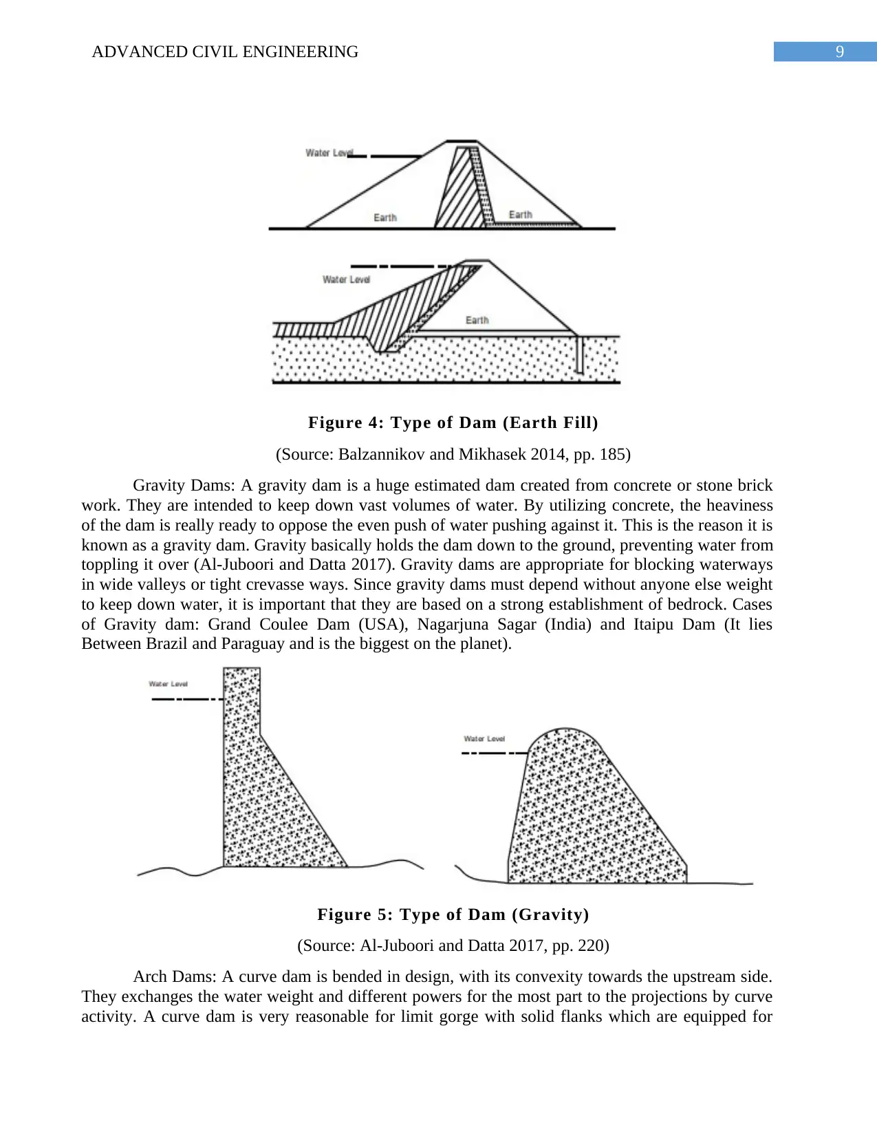
Gravity Dams: A gravity dam is a huge estimated dam created from concrete or stone brick
work. They are intended to keep down vast volumes of water. By utilizing concrete, the heaviness
of the dam is really ready to oppose the even push of water pushing against it. This is the reason it is
known as a gravity dam. Gravity basically holds the dam down to the ground, preventing water from
toppling it over (Al-Juboori and Datta 2017). Gravity dams are appropriate for blocking waterways
in wide valleys or tight crevasse ways. Since gravity dams must depend without anyone else weight
to keep down water, it is important that they are based on a strong establishment of bedrock. Cases
of Gravity dam: Grand Coulee Dam (USA), Nagarjuna Sagar (India) and Itaipu Dam (It lies
Between Brazil and Paraguay and is the biggest on the planet).
Figure 5: Type of Dam (Gravity)
(Source: Al-Juboori and Datta 2017, pp. 220)
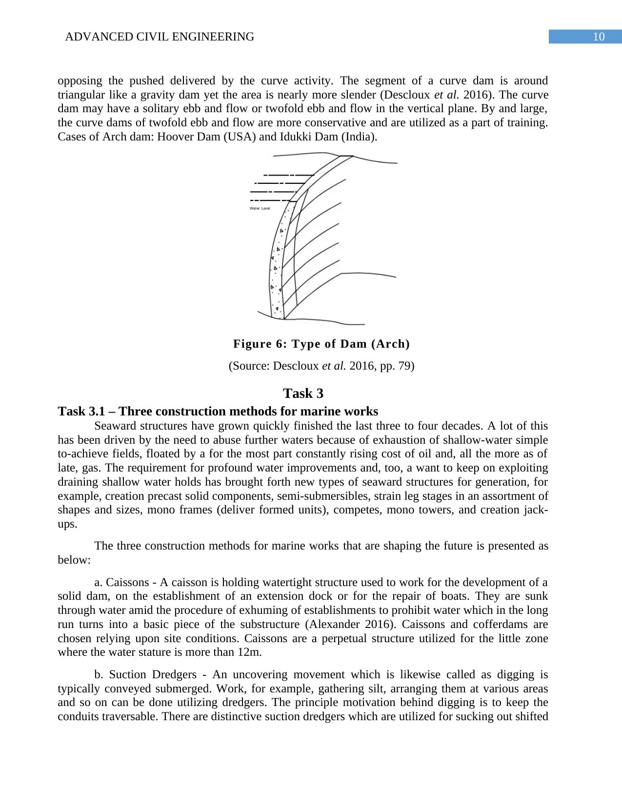
Arch Dams: A curve dam is bended in design, with its convexity towards the upstream side.
They exchanges the water weight and different powers for the most part to the projections by curve
activity. A curve dam is very reasonable for limit gorge with solid flanks which are equipped for
Figure 4: Type of Dam (Earth Fill)
(Source: Balzannikov and Mikhasek 2014, pp. 185)
Gravity Dams: A gravity dam is a huge estimated dam created from concrete or stone brick
work. They are intended to keep down vast volumes of water. By utilizing concrete, the heaviness
of the dam is really ready to oppose the even push of water pushing against it. This is the reason it is
known as a gravity dam. Gravity basically holds the dam down to the ground, preventing water from
toppling it over (Al-Juboori and Datta 2017). Gravity dams are appropriate for blocking waterways
in wide valleys or tight crevasse ways. Since gravity dams must depend without anyone else weight
to keep down water, it is important that they are based on a strong establishment of bedrock. Cases
of Gravity dam: Grand Coulee Dam (USA), Nagarjuna Sagar (India) and Itaipu Dam (It lies
Between Brazil and Paraguay and is the biggest on the planet).
Figure 5: Type of Dam (Gravity)
(Source: Al-Juboori and Datta 2017, pp. 220)
Arch Dams: A curve dam is bended in design, with its convexity towards the upstream side.
They exchanges the water weight and different powers for the most part to the projections by curve
activity. A curve dam is very reasonable for limit gorge with solid flanks which are equipped for
Secure Best Marks with AI Grader
Need help grading? Try our AI Grader for instant feedback on your assignments.
10ADVANCED CIVIL ENGINEERING
opposing the pushed delivered by the curve activity. The segment of a curve dam is around
triangular like a gravity dam yet the area is nearly more slender (Descloux et al. 2016). The curve
dam may have a solitary ebb and flow or twofold ebb and flow in the vertical plane. By and large,
the curve dams of twofold ebb and flow are more conservative and are utilized as a part of training.
Cases of Arch dam: Hoover Dam (USA) and Idukki Dam (India).
Figure 6: Type of Dam (Arch)
(Source: Descloux et al. 2016, pp. 79)
Task 3
Task 3.1 – Three construction methods for marine works
Seaward structures have grown quickly finished the last three to four decades. A lot of this
has been driven by the need to abuse further waters because of exhaustion of shallow-water simple
to-achieve fields, floated by a for the most part constantly rising cost of oil and, all the more as of
late, gas. The requirement for profound water improvements and, too, a want to keep on exploiting
draining shallow water holds has brought forth new types of seaward structures for generation, for
example, creation precast solid components, semi-submersibles, strain leg stages in an assortment of
shapes and sizes, mono frames (deliver formed units), competes, mono towers, and creation jack-
ups.
The three construction methods for marine works that are shaping the future is presented as
below:
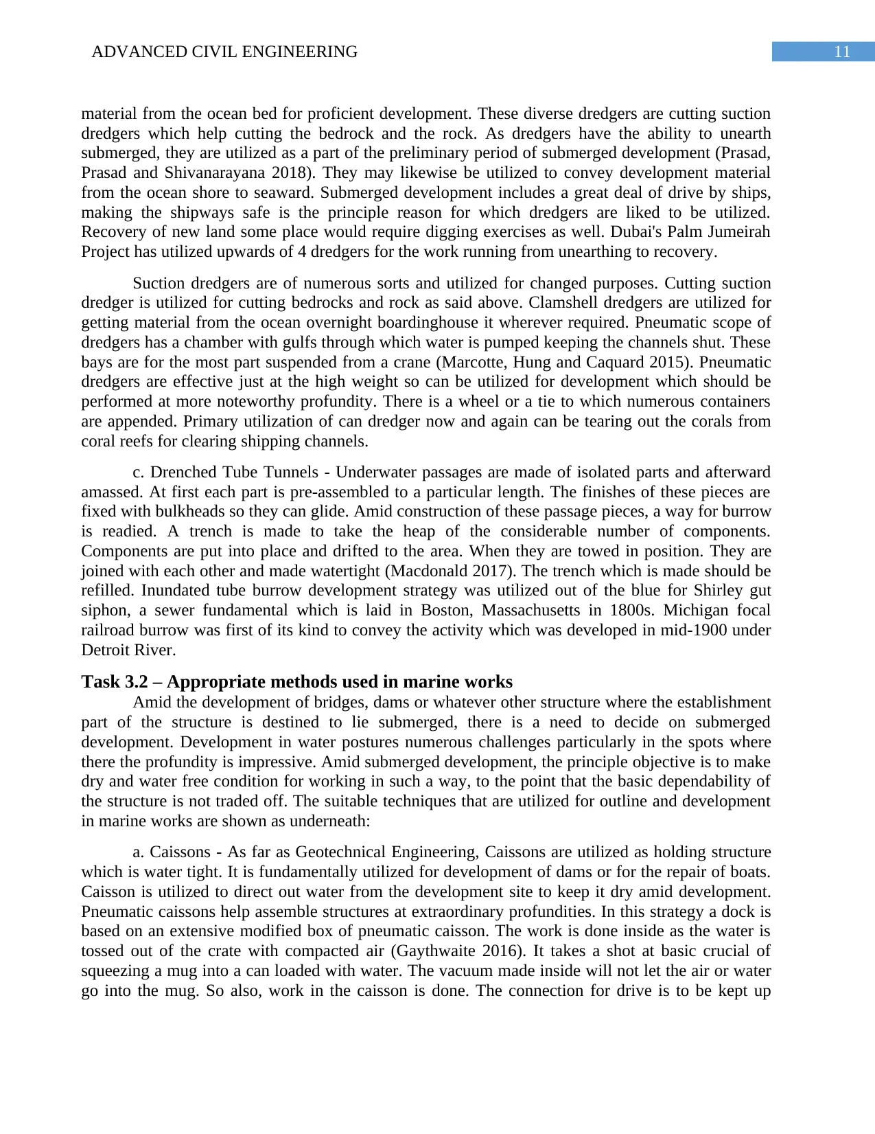
a. Caissons - A caisson is holding watertight structure used to work for the development of a
solid dam, on the establishment of an extension dock or for the repair of boats. They are sunk
through water amid the procedure of exhuming of establishments to prohibit water which in the long
run turns into a basic piece of the substructure (Alexander 2016). Caissons and cofferdams are
chosen relying upon site conditions. Caissons are a perpetual structure utilized for the little zone
where the water stature is more than 12m.
b. Suction Dredgers - An uncovering movement which is likewise called as digging is
typically conveyed submerged. Work, for example, gathering silt, arranging them at various areas
and so on can be done utilizing dredgers. The principle motivation behind digging is to keep the
conduits traversable. There are distinctive suction dredgers which are utilized for sucking out shifted
opposing the pushed delivered by the curve activity. The segment of a curve dam is around
triangular like a gravity dam yet the area is nearly more slender (Descloux et al. 2016). The curve
dam may have a solitary ebb and flow or twofold ebb and flow in the vertical plane. By and large,
the curve dams of twofold ebb and flow are more conservative and are utilized as a part of training.
Cases of Arch dam: Hoover Dam (USA) and Idukki Dam (India).
Figure 6: Type of Dam (Arch)
(Source: Descloux et al. 2016, pp. 79)
Task 3
Task 3.1 – Three construction methods for marine works
Seaward structures have grown quickly finished the last three to four decades. A lot of this
has been driven by the need to abuse further waters because of exhaustion of shallow-water simple
to-achieve fields, floated by a for the most part constantly rising cost of oil and, all the more as of
late, gas. The requirement for profound water improvements and, too, a want to keep on exploiting
draining shallow water holds has brought forth new types of seaward structures for generation, for
example, creation precast solid components, semi-submersibles, strain leg stages in an assortment of
shapes and sizes, mono frames (deliver formed units), competes, mono towers, and creation jack-
ups.
The three construction methods for marine works that are shaping the future is presented as
below:
a. Caissons - A caisson is holding watertight structure used to work for the development of a
solid dam, on the establishment of an extension dock or for the repair of boats. They are sunk
through water amid the procedure of exhuming of establishments to prohibit water which in the long
run turns into a basic piece of the substructure (Alexander 2016). Caissons and cofferdams are
chosen relying upon site conditions. Caissons are a perpetual structure utilized for the little zone
where the water stature is more than 12m.
b. Suction Dredgers - An uncovering movement which is likewise called as digging is
typically conveyed submerged. Work, for example, gathering silt, arranging them at various areas
and so on can be done utilizing dredgers. The principle motivation behind digging is to keep the
conduits traversable. There are distinctive suction dredgers which are utilized for sucking out shifted
11ADVANCED CIVIL ENGINEERING
material from the ocean bed for proficient development. These diverse dredgers are cutting suction
dredgers which help cutting the bedrock and the rock. As dredgers have the ability to unearth
submerged, they are utilized as a part of the preliminary period of submerged development (Prasad,
Prasad and Shivanarayana 2018). They may likewise be utilized to convey development material
from the ocean shore to seaward. Submerged development includes a great deal of drive by ships,
making the shipways safe is the principle reason for which dredgers are liked to be utilized.
Recovery of new land some place would require digging exercises as well. Dubai's Palm Jumeirah
Project has utilized upwards of 4 dredgers for the work running from unearthing to recovery.
Suction dredgers are of numerous sorts and utilized for changed purposes. Cutting suction
dredger is utilized for cutting bedrocks and rock as said above. Clamshell dredgers are utilized for
getting material from the ocean overnight boardinghouse it wherever required. Pneumatic scope of
dredgers has a chamber with gulfs through which water is pumped keeping the channels shut. These
bays are for the most part suspended from a crane (Marcotte, Hung and Caquard 2015). Pneumatic
dredgers are effective just at the high weight so can be utilized for development which should be
performed at more noteworthy profundity. There is a wheel or a tie to which numerous containers
are appended. Primary utilization of can dredger now and again can be tearing out the corals from
coral reefs for clearing shipping channels.
c. Drenched Tube Tunnels - Underwater passages are made of isolated parts and afterward
amassed. At first each part is pre-assembled to a particular length. The finishes of these pieces are
fixed with bulkheads so they can glide. Amid construction of these passage pieces, a way for burrow
is readied. A trench is made to take the heap of the considerable number of components.
Components are put into place and drifted to the area. When they are towed in position. They are
joined with each other and made watertight (Macdonald 2017). The trench which is made should be
refilled. Inundated tube burrow development strategy was utilized out of the blue for Shirley gut
siphon, a sewer fundamental which is laid in Boston, Massachusetts in 1800s. Michigan focal
railroad burrow was first of its kind to convey the activity which was developed in mid-1900 under
Detroit River.
Task 3.2 – Appropriate methods used in marine works
Amid the development of bridges, dams or whatever other structure where the establishment
part of the structure is destined to lie submerged, there is a need to decide on submerged
development. Development in water postures numerous challenges particularly in the spots where
there the profundity is impressive. Amid submerged development, the principle objective is to make
dry and water free condition for working in such a way, to the point that the basic dependability of
the structure is not traded off. The suitable techniques that are utilized for outline and development
in marine works are shown as underneath:
a. Caissons - As far as Geotechnical Engineering, Caissons are utilized as holding structure
which is water tight. It is fundamentally utilized for development of dams or for the repair of boats.
Caisson is utilized to direct out water from the development site to keep it dry amid development.
Pneumatic caissons help assemble structures at extraordinary profundities. In this strategy a dock is
based on an extensive modified box of pneumatic caisson. The work is done inside as the water is
tossed out of the crate with compacted air (Gaythwaite 2016). It takes a shot at basic crucial of
squeezing a mug into a can loaded with water. The vacuum made inside will not let the air or water
go into the mug. So also, work in the caisson is done. The connection for drive is to be kept up
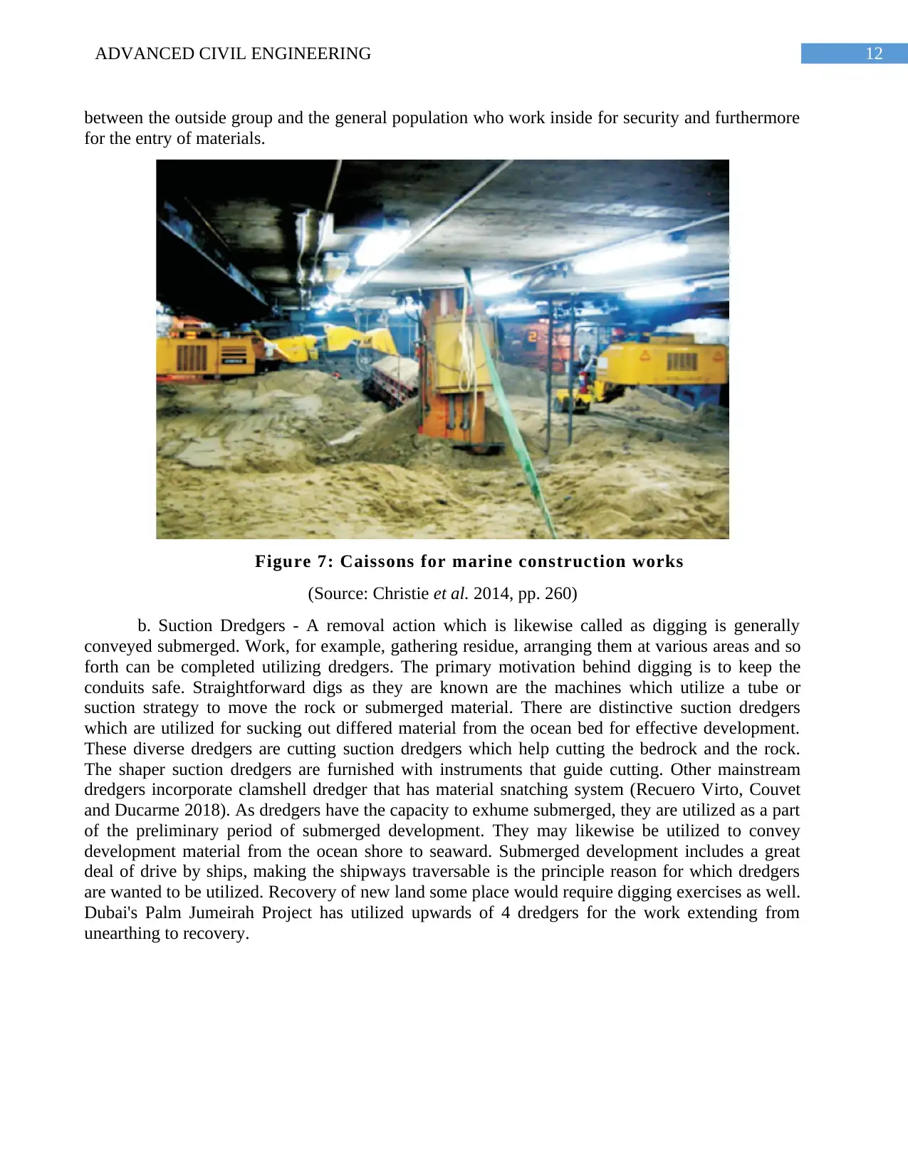
12ADVANCED CIVIL ENGINEERING
between the outside group and the general population who work inside for security and furthermore
for the entry of materials.
Figure 7: Caissons for marine construction works
(Source: Christie et al. 2014, pp. 260)
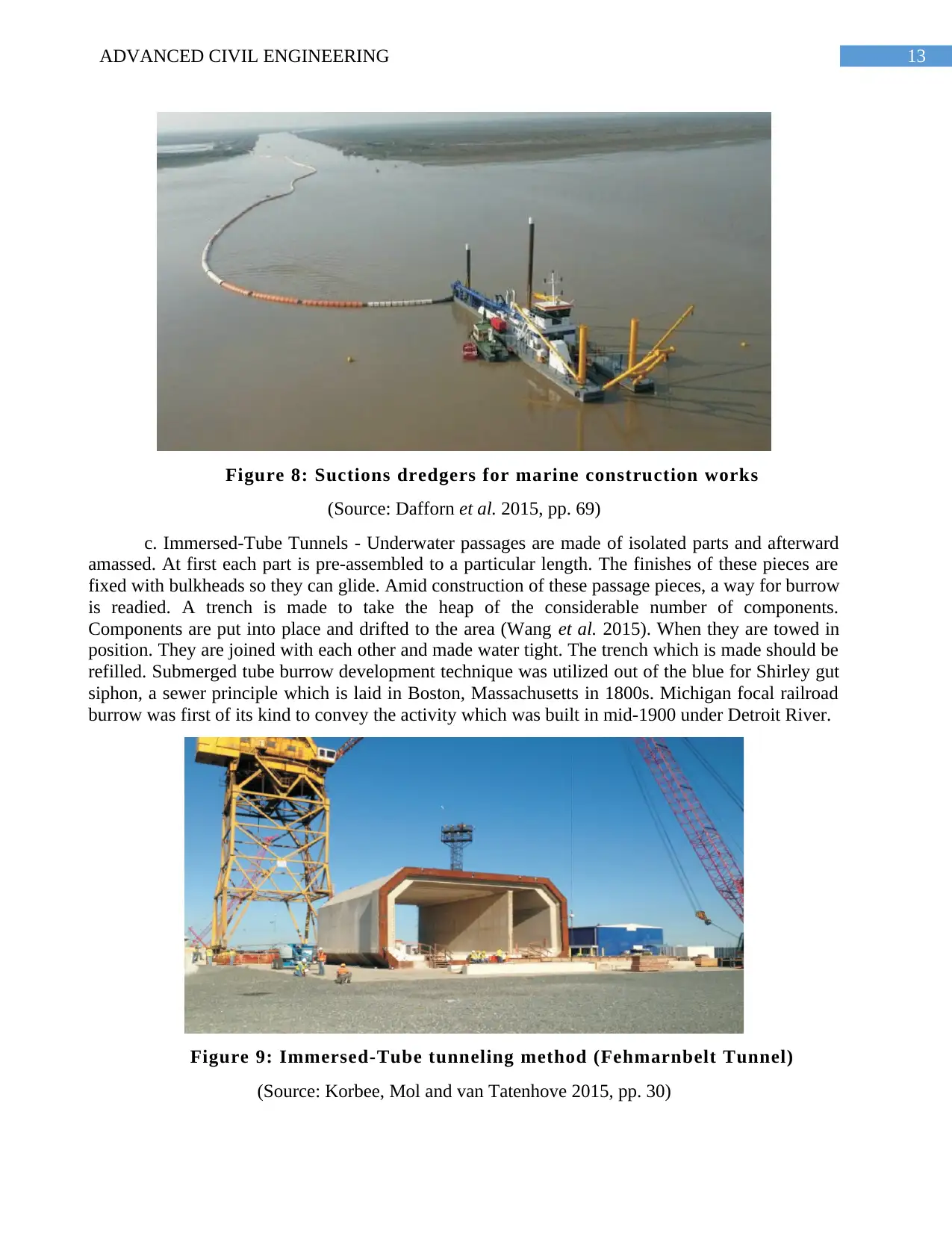
b. Suction Dredgers - A removal action which is likewise called as digging is generally
conveyed submerged. Work, for example, gathering residue, arranging them at various areas and so
forth can be completed utilizing dredgers. The primary motivation behind digging is to keep the
conduits safe. Straightforward digs as they are known are the machines which utilize a tube or
suction strategy to move the rock or submerged material. There are distinctive suction dredgers
which are utilized for sucking out differed material from the ocean bed for effective development.
These diverse dredgers are cutting suction dredgers which help cutting the bedrock and the rock.
The shaper suction dredgers are furnished with instruments that guide cutting. Other mainstream
dredgers incorporate clamshell dredger that has material snatching system (Recuero Virto, Couvet
and Ducarme 2018). As dredgers have the capacity to exhume submerged, they are utilized as a part
of the preliminary period of submerged development. They may likewise be utilized to convey
development material from the ocean shore to seaward. Submerged development includes a great
deal of drive by ships, making the shipways traversable is the principle reason for which dredgers
are wanted to be utilized. Recovery of new land some place would require digging exercises as well.
Dubai's Palm Jumeirah Project has utilized upwards of 4 dredgers for the work extending from
unearthing to recovery.
between the outside group and the general population who work inside for security and furthermore
for the entry of materials.
Figure 7: Caissons for marine construction works
(Source: Christie et al. 2014, pp. 260)
b. Suction Dredgers - A removal action which is likewise called as digging is generally
conveyed submerged. Work, for example, gathering residue, arranging them at various areas and so
forth can be completed utilizing dredgers. The primary motivation behind digging is to keep the
conduits safe. Straightforward digs as they are known are the machines which utilize a tube or
suction strategy to move the rock or submerged material. There are distinctive suction dredgers
which are utilized for sucking out differed material from the ocean bed for effective development.
These diverse dredgers are cutting suction dredgers which help cutting the bedrock and the rock.
The shaper suction dredgers are furnished with instruments that guide cutting. Other mainstream
dredgers incorporate clamshell dredger that has material snatching system (Recuero Virto, Couvet
and Ducarme 2018). As dredgers have the capacity to exhume submerged, they are utilized as a part
of the preliminary period of submerged development. They may likewise be utilized to convey
development material from the ocean shore to seaward. Submerged development includes a great
deal of drive by ships, making the shipways traversable is the principle reason for which dredgers
are wanted to be utilized. Recovery of new land some place would require digging exercises as well.
Dubai's Palm Jumeirah Project has utilized upwards of 4 dredgers for the work extending from
unearthing to recovery.
Paraphrase This Document
Need a fresh take? Get an instant paraphrase of this document with our AI Paraphraser
13ADVANCED CIVIL ENGINEERING
Figure 8: Suctions dredgers for marine construction works
(Source: Dafforn et al. 2015, pp. 69)
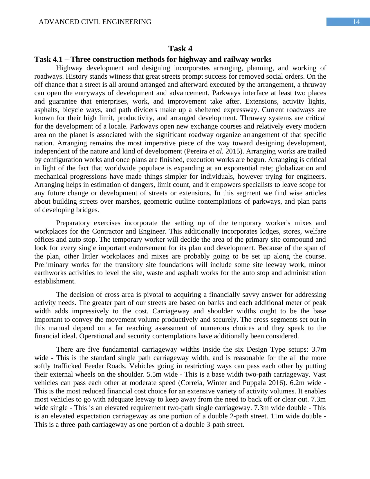
c. Immersed-Tube Tunnels - Underwater passages are made of isolated parts and afterward
amassed. At first each part is pre-assembled to a particular length. The finishes of these pieces are
fixed with bulkheads so they can glide. Amid construction of these passage pieces, a way for burrow
is readied. A trench is made to take the heap of the considerable number of components.
Components are put into place and drifted to the area (Wang et al. 2015). When they are towed in
position. They are joined with each other and made water tight. The trench which is made should be
refilled. Submerged tube burrow development technique was utilized out of the blue for Shirley gut
siphon, a sewer principle which is laid in Boston, Massachusetts in 1800s. Michigan focal railroad
burrow was first of its kind to convey the activity which was built in mid-1900 under Detroit River.
Figure 9: Immersed-Tube tunneling method (Fehmarnbelt Tunnel)
(Source: Korbee, Mol and van Tatenhove 2015, pp. 30)
Figure 8: Suctions dredgers for marine construction works
(Source: Dafforn et al. 2015, pp. 69)
c. Immersed-Tube Tunnels - Underwater passages are made of isolated parts and afterward
amassed. At first each part is pre-assembled to a particular length. The finishes of these pieces are
fixed with bulkheads so they can glide. Amid construction of these passage pieces, a way for burrow
is readied. A trench is made to take the heap of the considerable number of components.
Components are put into place and drifted to the area (Wang et al. 2015). When they are towed in
position. They are joined with each other and made water tight. The trench which is made should be
refilled. Submerged tube burrow development technique was utilized out of the blue for Shirley gut
siphon, a sewer principle which is laid in Boston, Massachusetts in 1800s. Michigan focal railroad
burrow was first of its kind to convey the activity which was built in mid-1900 under Detroit River.
Figure 9: Immersed-Tube tunneling method (Fehmarnbelt Tunnel)
(Source: Korbee, Mol and van Tatenhove 2015, pp. 30)
14ADVANCED CIVIL ENGINEERING
Task 4
Task 4.1 – Three construction methods for highway and railway works
Highway development and designing incorporates arranging, planning, and working of
roadways. History stands witness that great streets prompt success for removed social orders. On the
off chance that a street is all around arranged and afterward executed by the arrangement, a thruway
can open the entryways of development and advancement. Parkways interface at least two places
and guarantee that enterprises, work, and improvement take after. Extensions, activity lights,
asphalts, bicycle ways, and path dividers make up a sheltered expressway. Current roadways are
known for their high limit, productivity, and arranged development. Thruway systems are critical
for the development of a locale. Parkways open new exchange courses and relatively every modern
area on the planet is associated with the significant roadway organize arrangement of that specific
nation. Arranging remains the most imperative piece of the way toward designing development,
independent of the nature and kind of development (Pereira et al. 2015). Arranging works are trailed
by configuration works and once plans are finished, execution works are begun. Arranging is critical
in light of the fact that worldwide populace is expanding at an exponential rate; globalization and
mechanical progressions have made things simpler for individuals, however trying for engineers.
Arranging helps in estimation of dangers, limit count, and it empowers specialists to leave scope for
any future change or development of streets or extensions. In this segment we find wise articles
about building streets over marshes, geometric outline contemplations of parkways, and plan parts
of developing bridges.
Preparatory exercises incorporate the setting up of the temporary worker's mixes and
workplaces for the Contractor and Engineer. This additionally incorporates lodges, stores, welfare
offices and auto stop. The temporary worker will decide the area of the primary site compound and
look for every single important endorsement for its plan and development. Because of the span of
the plan, other littler workplaces and mixes are probably going to be set up along the course.
Preliminary works for the transitory site foundations will include some site leeway work, minor
earthworks activities to level the site, waste and asphalt works for the auto stop and administration
establishment.
The decision of cross-area is pivotal to acquiring a financially savvy answer for addressing
activity needs. The greater part of our streets are based on banks and each additional meter of peak
width adds impressively to the cost. Carriageway and shoulder widths ought to be the base
important to convey the movement volume productively and securely. The cross-segments set out in
this manual depend on a far reaching assessment of numerous choices and they speak to the
financial ideal. Operational and security contemplations have additionally been considered.
There are five fundamental carriageway widths inside the six Design Type setups: 3.7m
wide - This is the standard single path carriageway width, and is reasonable for the all the more
softly trafficked Feeder Roads. Vehicles going in restricting ways can pass each other by putting
their external wheels on the shoulder. 5.5m wide - This is a base width two-path carriageway. Vast
vehicles can pass each other at moderate speed (Correia, Winter and Puppala 2016). 6.2m wide -
This is the most reduced financial cost choice for an extensive variety of activity volumes. It enables
most vehicles to go with adequate leeway to keep away from the need to back off or clear out. 7.3m
wide single - This is an elevated requirement two-path single carriageway. 7.3m wide double - This
is an elevated expectation carriageway as one portion of a double 2-path street. 11m wide double -
This is a three-path carriageway as one portion of a double 3-path street.
15ADVANCED CIVIL ENGINEERING
The choice of an 11m wide single carriageway street, as proposed in RMSS, has not been
received in light of worries that the wide carriageway would support hazardous surpassing. English
involvement with 11m single carriageway streets is that, while their general wellbeing record is
great, they do have a higher-than-normal extent of overwhelming mishaps. Shoulders are basic for
security and limit, and should be given on all streets (Delmastro, Lavagno and Schranz 2016). Ideal
widths for shoulders are 1.2m, 1.5m, and 1.8m. All shoulders must be cleared keeping in mind the
end goal to be tough and perform successfully in all climates. This can be accomplished either by
broadening the primary asphalt or utilizing an alternate development, for example, twofold
bituminous seal treatment.
Task 4.2 – Appropriate methods used in highway and railway works
Roads are built to convey advantages to the general population. Interest in streets is gigantic
for which financing most time is restricted. Accordingly the choice to put and secure the interest in
type of upkeep is critical in order to bring ideal advantages and incentive for cash. Most street
extends today include changes to existing roadways, and the arranging, activity, and upkeep of such
tasks regularly are open doors for enhancing biological conditions. A developing assemblage of data
portrays such practices for enhancing amphibian and earthly natural surroundings. The numerous
open doors that emerge for alleviating or diminishing antagonistic ecological effects in changes and
repairs to existing streets ought not to be neglected (Xue et al. 2015). Natural contemplations ought
to be incorporated when designs are made to repair or change existing streets, and in addition when
designs are made to assemble new streets.
Keeping in mind the end goal to amplify the advantages in the decision of speculation, street
venture examination may well be a piece of the arranging procedure. The reason for monetary
examination is to decide the venture cost and financial returns anticipated from such speculation.
Venture cost comprises of development and yearly upkeep costs and are regularly carried by the
street office. While monetary returns is in type of reserve funds to the street clients coming about
because of new street office (Verweij 2015). These expenses are referred to as aggregate (street)
transport cost or entire life cycle cost. It is consequently important to decide the works that will limit
the aggregate transport cost over the broadened investigation period, say expected existence of the
street.
Arranging limits for streets and surveying related natural impacts are regularly in light of
financial contemplations, bringing about a jumble between arranging scales and spatial scales at
which biological frameworks work. To some extent, this confuse comes about in light of the fact
that there are couple of legitimate motivating forces or disincentives to think about natural impacts
past political purviews, and consequently basic leadership remains essentially nearby. The
environmental impacts of streets are regularly significantly bigger than the street itself, and they
frequently stretch out past territorial arranging areas (Gautier 2015). Logical writing on natural
impacts of streets for the most part tends to neighborhood to-middle of the road scales, and a large
number of those impacts are very much reported. Be that as it may, there are couple of integrative or
extensive scale considers. At times the suitable spatial scale for natural research is not known ahead
of time, and all things considered, some biological impacts of streets may go undetected if an
improper scale is picked. Barely any investigations have tended to the mind boggling nature of the
environmental impacts of streets, and the examinations that have done as such were regularly in
view of little testing periods and lacking inspecting of the scope of changeability in biological
frameworks.
Secure Best Marks with AI Grader
Need help grading? Try our AI Grader for instant feedback on your assignments.
16ADVANCED CIVIL ENGINEERING
The appraisal of the combined effects of street development and utilize is from time to time
sufficient. Although numerous laws, directions, and approaches require some thought of biological
impacts of transportation exercises, for example, street development, the lawful structure leaves
significant holes in the necessities. Effects on specific assets are ordinarily approved through grants.
Allowing programs normally think about just direct effects of street development and use on a
secured asset, despite the fact that circuitous or combined impacts can be considerable (for instance,
consequences for nourishment web segments). The incremental impacts of numerous effects after
some time could be critical to such assets as wetlands or untamed life.
Task 5
Task 5.1 – Appropriate solutions for slope stabilization
Slope adjustment is characterized as an arrangement of perpetual outline measures utilized
alone or in mix to limit disintegration from bothered surfaces. The motivation behind this system is
to balance out the dirt, to decrease raindrop affect, to diminish the speed of surface spillover, and to
avert disintegration. It is relevant to cleared, reviewed, aggravated inclines, or where vegetation
alone does not give satisfactory disintegration insurance. The different arrangements that are
utilized for incline adjustment is examined as underneath:
Rock Slope Protection – It is characterized as a layer of free shake or total put over an
erodible soil surface. Shake incline insurance can be utilized with an assortment of BMPs to
separate the framework as opposed to having an expansive traverse of the same BMP. Woody
vegetation planted in interstices yields a stylishly satisfying structure (Oset et al. 2014). Consider
utilizing rock slope insurance if favored shake is locally accessible. On the off chance that
appropriately introduced, shake incline security requires little upkeep. Assess intermittently to check
whether rocks have been removed.
Rock slope insurance is most appropriate in regions where revegetation is troublesome, and
is frequently utilized on soak inclines above holding dividers. Shake slope assurance ought to be
executed just when hydrologic conditions deny elective adjustment. A few territories limit the
utilization of shake slope security neighboring privileges of-way. Where possible, shake slope
insurance ought to evaded where it might be viewed as ugly or represents an open security risk.
Incline Roughening, Terracing, and Rounding - Various alterations made to cut or fill slopes
including porches, seats, steps, and serrations intended to limit disintegration potential or overflow
starting on the slope and diminish the danger of avalanches or potentially stone fall. Slope forming
practices to diminish disintegration potential should mix with the characteristic scene. Most extreme
Slope Stabilization Techniques November 2001 6-3 strength is accomplished when lasting
revegetation has been set up (Kim and Han 2016). Slope molding can give positive destinations to
plant foundation. Know that crown jewels created amid slope molding should be expelled and
discarded at an endorsed site. In the event that topsoil is evacuated, store for swap nearby or use for
future tasks needing topsoil. Patios can be huge or little and are regularly referred to as seats, steps
or serrations, contingent upon measure. The choice to introduce a seat, step, or serration relies upon
the length and level of the incline. Longer or more extreme inclines may require seats while shorter,
less steep slopes might be balanced out with steps and serrations. Patios should be reviewed
occasionally for harm coming about because of surface overflow. If not repaired, rills and ravines
may create. Gathered silt ought to be evacuated to anticipate passage into the tempest deplete
framework. Hardware might be utilized for dregs expulsion if site conditions allow; something else,
17ADVANCED CIVIL ENGINEERING
work must be performed by hand (Celauro et al. 2015). Support exercises have the potential for
expanding disintegration potential; restrain re-aggravation when conceivable.
Slope forming is appropriate for expansive cut and fill inclines, particularly those related
with roadway development. Slope molding is by and large ineffectual on disintegrated granitic soils
because of exorbitant sloughing of material. In that capacity, this training has constrained
materialness in the Lake Tahoe Basin. Incline molding strategies ought not to be executed in
territories with high groundwater.
Mulches - Temporary or perpetual hindrance to shield exposed or exasperates soil from
raindrop affect, lessen spillover speed, and ensure against disintegration. Use of mulch material is
one of the least demanding, most financially savvy approaches to incidentally balance out free soil.
There are a few choices for compelling mulching including pine needles, wood chips, and
hydromulch. Pine needles are the favored local mulch, as they last longer than different mulches and
might be a wellspring of long haul natural nitrogen. Mulched regions ought to be assessed routinely
for satisfactory cover and remulched as required. Mulch ought to be connected where soil has been
bothered and vegetation has been expelled (Chong et al. 2016). Hydromulch is prescribed for steep,
out of reach territories. Mulch is not appropriate to exceptionally soak inclines or to a great degree
sandy soils. Abstain from utilizing as a part of immersed regions, for example, wetlands or stream
condition zones. Mulch is viewed as an impermanent BMP; it ought not to be depended on for long
haul incline adjustment.
Disintegration Control Mats/Blankets - Erosion control covers as well as mats are
nonspecific terms given to textures or geotextiles that are set in coordinate contact with the dirt for
impermanent disintegration control. Disintegration control covers/mats give a defensive layer to
exposed soils for adjustment and shield the surface from raindrop affect. Tangles and covers are
accessible in an assortment of widths/sizes. Covers are effortlessly moved onto evaluated surfaces
and safely stapled to give uniform scope. Covers/mats can be utilized with long haul revegetation
hones. On the off chance that legitimately introduced, disintegration control covers/mats furnish
powerful soil assurance with little upkeep (Machelski 2015). Covers/mats ought to be reviewed
intermittently and repaired as required. Disintegration control covers/mats are savvy strategies for
balancing out irritated soil on soak slopes and evaluated development locales. They can likewise be
utilized to balance out developed channel ways. Counsel the maker for proper use of a particular
item. Try not to utilize covers/tangles as a solitary technique for disintegration control. Try not to
use on ill-equipped soils. Covers ought to be considered as an impermanent BMP until the point that
adequate vegetation is set up; covers ought not to be viewed as a perpetual incline adjustment
strategy.
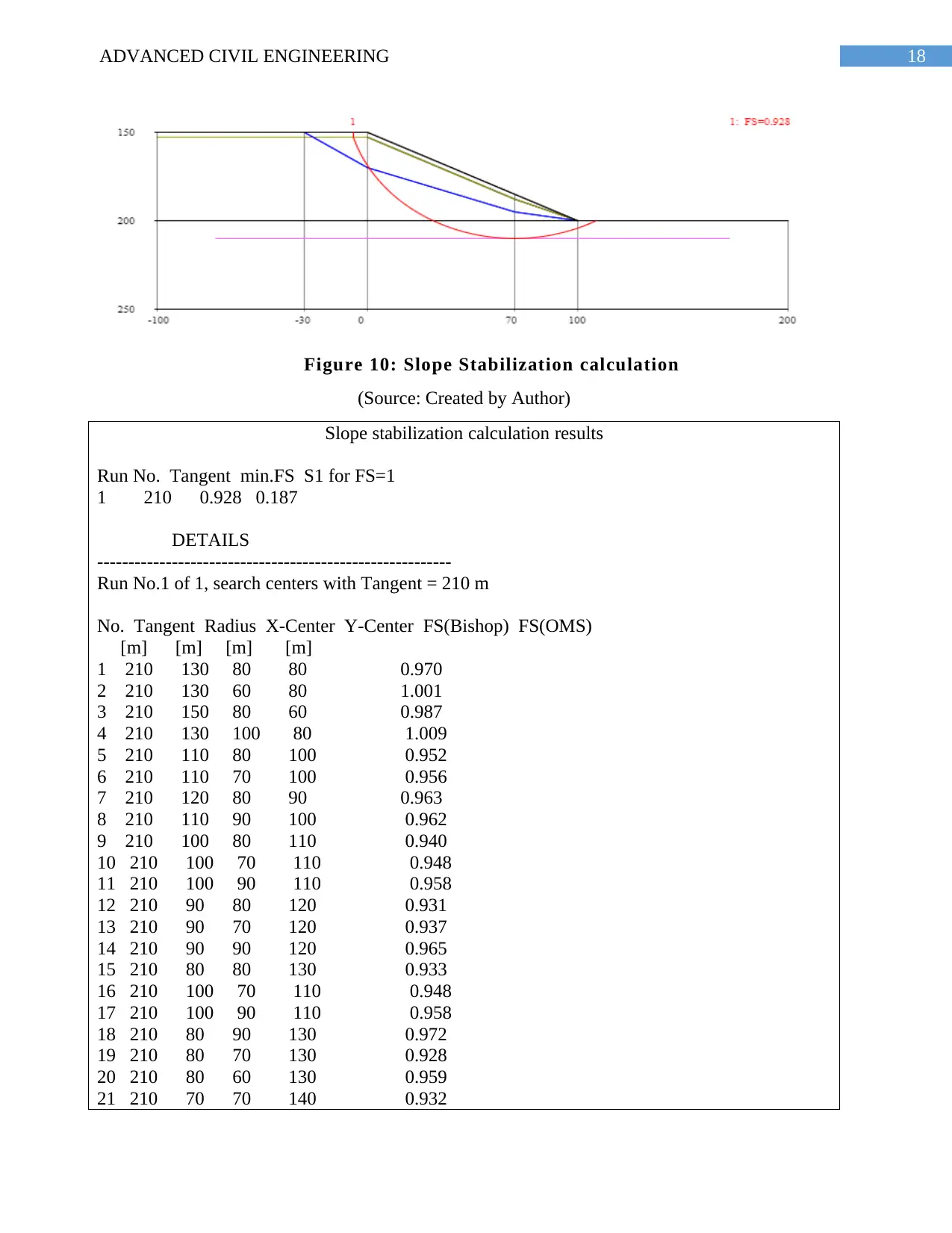
18ADVANCED CIVIL ENGINEERING
Figure 10: Slope Stabilization calculation
(Source: Created by Author)
Slope stabilization calculation results
Run No. Tangent min.FS S1 for FS=1
1 210 0.928 0.187
DETAILS
---------------------------------------------------------
Run No.1 of 1, search centers with Tangent = 210 m
No. Tangent Radius X-Center Y-Center FS(Bishop) FS(OMS)
[m] [m] [m] [m]
1 210 130 80 80 0.970
2 210 130 60 80 1.001
3 210 150 80 60 0.987
4 210 130 100 80 1.009
5 210 110 80 100 0.952
6 210 110 70 100 0.956
7 210 120 80 90 0.963
8 210 110 90 100 0.962
9 210 100 80 110 0.940
10 210 100 70 110 0.948
11 210 100 90 110 0.958
12 210 90 80 120 0.931
13 210 90 70 120 0.937
14 210 90 90 120 0.965
15 210 80 80 130 0.933
16 210 100 70 110 0.948
17 210 100 90 110 0.958
18 210 80 90 130 0.972
19 210 80 70 130 0.928
20 210 80 60 130 0.959
21 210 70 70 140 0.932
Paraphrase This Document
Need a fresh take? Get an instant paraphrase of this document with our AI Paraphraser
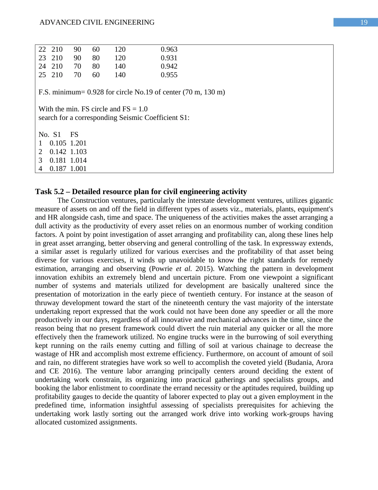
19ADVANCED CIVIL ENGINEERING
22 210 90 60 120 0.963
23 210 90 80 120 0.931
24 210 70 80 140 0.942
25 210 70 60 140 0.955
F.S. minimum= 0.928 for circle No.19 of center (70 m, 130 m)
With the min. FS circle and FS = 1.0
search for a corresponding Seismic Coefficient S1:
No. S1 FS
1 0.105 1.201
2 0.142 1.103
3 0.181 1.014
4 0.187 1.001
Task 5.2 – Detailed resource plan for civil engineering activity
The Construction ventures, particularly the interstate development ventures, utilizes gigantic
measure of assets on and off the field in different types of assets viz., materials, plants, equipment's
and HR alongside cash, time and space. The uniqueness of the activities makes the asset arranging a
dull activity as the productivity of every asset relies on an enormous number of working condition
factors. A point by point investigation of asset arranging and profitability can, along these lines help
in great asset arranging, better observing and general controlling of the task. In expressway extends,
a similar asset is regularly utilized for various exercises and the profitability of that asset being
diverse for various exercises, it winds up unavoidable to know the right standards for remedy
estimation, arranging and observing (Powrie et al. 2015). Watching the pattern in development
innovation exhibits an extremely blend and uncertain picture. From one viewpoint a significant
number of systems and materials utilized for development are basically unaltered since the
presentation of motorization in the early piece of twentieth century. For instance at the season of
thruway development toward the start of the nineteenth century the vast majority of the interstate
undertaking report expressed that the work could not have been done any speedier or all the more
productively in our days, regardless of all innovative and mechanical advances in the time, since the
reason being that no present framework could divert the ruin material any quicker or all the more
effectively then the framework utilized. No engine trucks were in the burrowing of soil everything
kept running on the rails enemy cutting and filling of soil at various chainage to decrease the
wastage of HR and accomplish most extreme efficiency. Furthermore, on account of amount of soil
and rain, no different strategies have work so well to accomplish the coveted yield (Budania, Arora
and CE 2016). The venture labor arranging principally centers around deciding the extent of
undertaking work constrain, its organizing into practical gatherings and specialists groups, and
booking the labor enlistment to coordinate the errand necessity or the aptitudes required, building up
profitability gauges to decide the quantity of laborer expected to play out a given employment in the
predefined time, information insightful assessing of specialists prerequisites for achieving the
undertaking work lastly sorting out the arranged work drive into working work-groups having
allocated customized assignments.
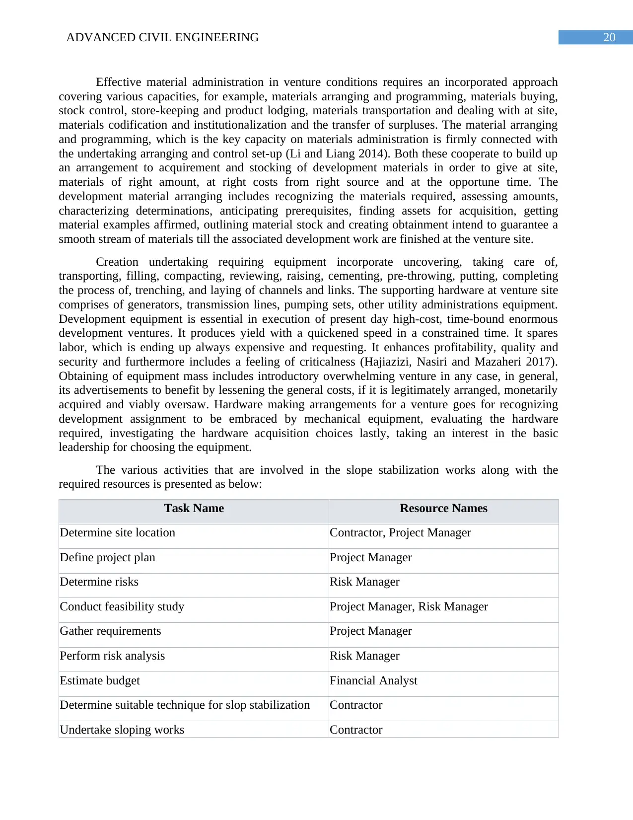
20ADVANCED CIVIL ENGINEERING
Effective material administration in venture conditions requires an incorporated approach
covering various capacities, for example, materials arranging and programming, materials buying,
stock control, store-keeping and product lodging, materials transportation and dealing with at site,
materials codification and institutionalization and the transfer of surpluses. The material arranging
and programming, which is the key capacity on materials administration is firmly connected with
the undertaking arranging and control set-up (Li and Liang 2014). Both these cooperate to build up
an arrangement to acquirement and stocking of development materials in order to give at site,
materials of right amount, at right costs from right source and at the opportune time. The
development material arranging includes recognizing the materials required, assessing amounts,
characterizing determinations, anticipating prerequisites, finding assets for acquisition, getting
material examples affirmed, outlining material stock and creating obtainment intend to guarantee a
smooth stream of materials till the associated development work are finished at the venture site.
Creation undertaking requiring equipment incorporate uncovering, taking care of,
transporting, filling, compacting, reviewing, raising, cementing, pre-throwing, putting, completing
the process of, trenching, and laying of channels and links. The supporting hardware at venture site
comprises of generators, transmission lines, pumping sets, other utility administrations equipment.
Development equipment is essential in execution of present day high-cost, time-bound enormous
development ventures. It produces yield with a quickened speed in a constrained time. It spares
labor, which is ending up always expensive and requesting. It enhances profitability, quality and
security and furthermore includes a feeling of criticalness (Hajiazizi, Nasiri and Mazaheri 2017).
Obtaining of equipment mass includes introductory overwhelming venture in any case, in general,
its advertisements to benefit by lessening the general costs, if it is legitimately arranged, monetarily
acquired and viably oversaw. Hardware making arrangements for a venture goes for recognizing
development assignment to be embraced by mechanical equipment, evaluating the hardware
required, investigating the hardware acquisition choices lastly, taking an interest in the basic
leadership for choosing the equipment.
The various activities that are involved in the slope stabilization works along with the
required resources is presented as below:
Task Name Resource Names
Determine site location Contractor, Project Manager
Define project plan Project Manager
Determine risks Risk Manager
Conduct feasibility study Project Manager, Risk Manager
Gather requirements Project Manager
Perform risk analysis Risk Manager
Estimate budget Financial Analyst
Determine suitable technique for slop stabilization Contractor
Undertake sloping works Contractor
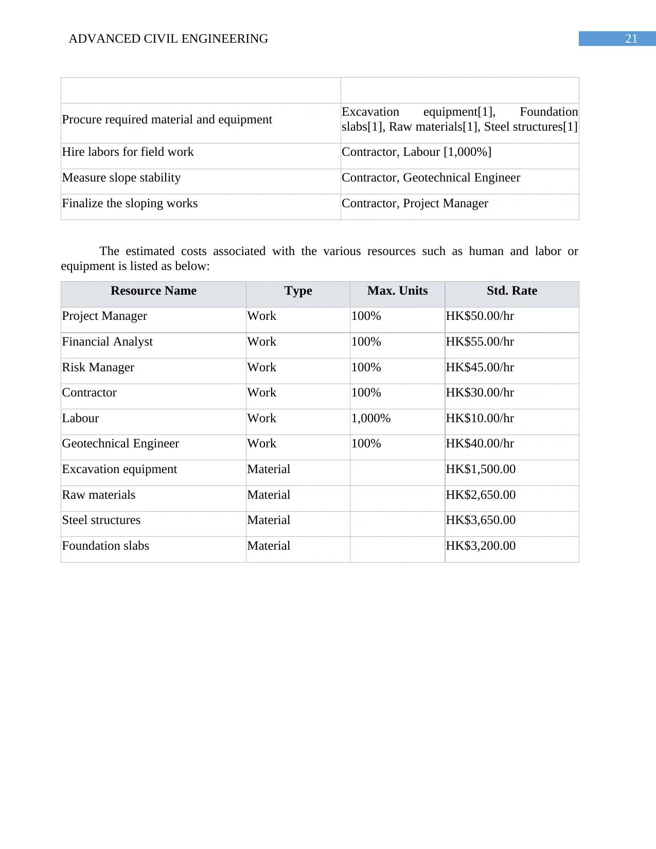
21ADVANCED CIVIL ENGINEERING
Procure required material and equipment Excavation equipment[1], Foundation
slabs[1], Raw materials[1], Steel structures[1]
Hire labors for field work Contractor, Labour [1,000%]
Measure slope stability Contractor, Geotechnical Engineer
Finalize the sloping works Contractor, Project Manager
The estimated costs associated with the various resources such as human and labor or
equipment is listed as below:
Resource Name Type Max. Units Std. Rate
Project Manager Work 100% HK$50.00/hr
Financial Analyst Work 100% HK$55.00/hr
Risk Manager Work 100% HK$45.00/hr
Contractor Work 100% HK$30.00/hr
Labour Work 1,000% HK$10.00/hr
Geotechnical Engineer Work 100% HK$40.00/hr
Excavation equipment Material HK$1,500.00
Raw materials Material HK$2,650.00
Steel structures Material HK$3,650.00
Foundation slabs Material HK$3,200.00
Secure Best Marks with AI Grader
Need help grading? Try our AI Grader for instant feedback on your assignments.
22ADVANCED CIVIL ENGINEERING
References
Alexander, M.G. ed., 2016. Marine Concrete Structures: Design, Durability and Performance.
Woodhead Publishing is.
Al-Juboori, M. and Datta, B., 2017. Influence of hydraulic conductivity and its anisotropy ratio on
the optimum hydraulic design of water retaining structures founded on permeable soils. In 13th
Hydraulics in Water Engineering Conference (p. 220). Engineers Australia.
Al-Juboori, M. and Datta, B., 2018. LINKED SIMULATION-OPTIMIZATION MODEL FOR
OPTIMUM HYDRAULIC DESIGN OF WATER RETAINING STRUCTURES CONSTRUCTED
ON PERMEABLE SOILS. International Journal, 14(44), pp.39-46.
Antucheviciene, J., Kala, Z., Marzouk, M. and Vaidogas, E.R., 2015. Decision making methods and
applications in civil engineering. Mathematical Problems in Engineering, 2015.
Arasan, S., Isik, F., Akbulut, R.K., Zaimoglu, A.S. and Nasirpur, O., 2015. Rapid stabilization of
sands with deep mixing method using polyester. Periodica Polytechnica. Civil Engineering, 59(3),
p.405.
Bai, Y., Yang, Z. and Jiang, Z., 2014. Key protection techniques adopted and analysis of influence
on adjacent buildings due to the Bund Tunnel construction. Tunnelling and Underground Space
Technology, 41, pp.24-34.
Bai, Y., Yang, Z. and Jiang, Z., 2015. Key protection techniques adopted and analysis of influence
on adjacent buildings due to the Bund Tunnel construction. Tunnelling and Underground Space
Technology, 41, pp.30-45.
Balzannikov, M.I. and Mikhasek, A.A., 2014. The use of modified composite materials in building
hydraulic engineering structures. Procedia Engineering, 91, pp.183-187.
Bazhenov, Y., Bulgakov, B. and Alexandrova, O., 2016. Modified fine-grained concrete for facing
and repair of the hydraulic structures. In MATEC Web of Conferences (Vol. 86, p. 03009). EDP
Sciences.
Brockmann, C., Brezinski, H. and Erbe, A., 2016. Innovation in construction megaprojects. Journal
of Construction Engineering and Management, 142(11), p.04016059.
Budania, R., Arora, R.P. and CE, C., 2016. Soil Nailing for Slope Stabilization: An
Overview. International Journal of Engineering Science, 3877.
Burr, A. ed., 2016. Delay and disruption in construction contracts. CRC Press.
Celauro, C., Corriere, F., Guerrieri, M. and Casto, B.L., 2015. Environmentally appraising different
pavement and construction scenarios: A comparative analysis for a typical local
road. Transportation Research Part D: Transport and Environment, 34, pp.41-51.
Chen, S.H. and Chen, M.L., 2016. Hydraulic structures. Springer.
Cheng, Y.M. and Lau, C.K., 2014. Slope stability analysis and stabilization: new methods and
insight. CRC Press.
23ADVANCED CIVIL ENGINEERING
Chong, H.Y., Lopez, R., Wang, J., Wang, X. and Zhao, Z., 2016. Comparative analysis on the
adoption and use of BIM in road infrastructure projects. Journal of Management in
Engineering, 32(6), p.05016021.
Christie, N., Smyth, K., Barnes, R. and Elliott, M., 2014. Co-location of activities and designations:
A means of solving or creating problems in marine spatial planning?. Marine Policy, 43, pp.254-
261.
Correia, A.G., Winter, M.G. and Puppala, A.J., 2016. A review of sustainable approaches in
transport infrastructure geotechnics. Transportation Geotechnics, 7, pp.21-28.
Cui, Q.L., Wu, H.N., Shen, S.L., Yin, Z.Y. and Horpibulsuk, S., 2016. Protection of neighbour
buildings due to construction of shield tunnel in mixed ground with sand over weathered
granite. Environmental Earth Sciences, 75(6), p.458.
Dafforn, K.A., Mayer-Pinto, M., Morris, R.L. and Waltham, N.J., 2015. Application of management
tools to integrate ecological principles with the design of marine infrastructure. Journal of
environmental management, 158, pp.61-73.
Daraei, A., Herki, B.M., Sherwani, A.F.H. and Zare, S., 2018. Slope Stability in Swelling Soils
Using Cement Grout: A Case Study. International Journal of Geosynthetics and Ground
Engineering, 4(1), p.10.
Delmastro, C., Lavagno, E. and Schranz, L., 2016. Underground urbanism: master plans and
sectorial plans. Tunnelling and Underground Space Technology, 55, pp.103-111.
Descloux, S., Chanudet, V., Taquet, B., Rode, W., Guédant, P., Serça, D., Deshmukh, C. and
Guerin, F., 2016. Efficiency of the Nam Theun 2 hydraulic structures on water aeration and methane
degassing. Hydroécologie Appliquée, 19, pp.63-86.
Ding, L., Zhang, L., Wu, X., Skibniewski, M.J. and Qunzhou, Y., 2014. Safety management in
tunnel construction: Case study of Wuhan metro construction in China. Safety science, 62, pp.8-15.
Fahimifar, A., Abdolmaleki, A. and Soltani, P., 2014. Stabilization of rock slopes using geogrid
boxes. Arabian Journal of Geosciences, 7(2), pp.609-621.
Garcia-Espinel, J.D., Castro-Fresno, D., Gayo, P.P. and Ballester-Muñoz, F., 2015. Effects of sea
water environment on glass fiber reinforced plastic materials used for marine civil engineering
constructions. Materials & Design (1980-2015), 66, pp.46-50.
Gautier, P.E., 2015. Slab track: Review of existing systems and optimization potentials including
very high speed. Construction and Building Materials, 92, pp.9-15.
Gaythwaite, J.W., 2016, November. Design of Marine Facilities: Engineering for Port and Harbor
Structures. American Society of Civil Engineers.
Glendinning, S., Hughes, P., Helm, P., Chambers, J., Mendes, J., Gunn, D., Wilkinson, P. and
Uhlemann, S., 2014. Construction, management and maintenance of embankments used for road
and rail infrastructure: implications of weather induced pore water pressures. Acta
Geotechnica, 9(5), pp.799-816.
24ADVANCED CIVIL ENGINEERING
Hajiazizi, M., Nasiri, M. and Mazaheri, A.R., 2017. The Effect of Fixed Piles Tip on Stabilization of
Earth Slopes. Scientia Iranica.
Jacques, D., Laverret, H., Ballu, N. and Reilly, J., 2017. SCL 1128-Hong Kong's first variable
density tunnel boring machine. In 16th Australasian Tunnelling Conference 2017: challenging
underground space: bigger, better, more (p. 240). Engineers Australia.
Kim, J.Y. and Han, J.H., 2016. Straw effects of new highway construction on local population and
employment growth. Habitat International, 53, pp.123-132.
Korbee, D., Mol, A.P. and van Tatenhove, J.P., 2015. Ecological considerations in constructing
marine infrastructure: The Falmouth cruise terminal development, Jamaica. Marine Policy, 56,
pp.23-32.
Li, L. and Liang, R.Y., 2014. Limit equilibrium based design approach for slope stabilization using
multiple rows of drilled shafts. Computers and Geotechnics, 59, pp.67-74.
Li, L. and Liang, R.Y., 2014. Reliability‐based design for slopes reinforced with a row of drilled
shafts. International Journal for Numerical and Analytical Methods in Geomechanics, 38(2),
pp.202-220.
Li, P., Zhao, Y. and Zhou, X., 2016. Displacement characteristics of high-speed railway tunnel
construction in loess ground by using multi-step excavation method. Tunnelling and Underground
Space Technology, 51, pp.41-55.
Liang, D.X., Jiang, Z.Q., Zhu, S.Y., Sun, Q. and Qian, Z.W., 2016. Experimental research on water
inrush in tunnel construction. Natural hazards, 81(1), pp.467-480.
Liu, W., Zhao, T., Zhou, W. and Tang, J., 2018. Safety risk factors of metro tunnel construction in
China: An integrated study with EFA and SEM. Safety Science, 105, pp.98-113.
Macdonald, H., 2017. Marine Concrete Structures–Design, Durability and Performance, Mark
Alexander (Ed.). Civil Engineering= Siviele Ingenieurswese, 2017(v25i2), pp.46-48.
Machelski, C., 2015. Stiffness of railway soil-steel structures. Studia Geotechnica et
Mechanica, 37(4), pp.29-36.
Malik, I.A.G., Dafalla, D.S. and Ibrahim, A., 2015. Rock Slope Stabilization and Protection for
Roads and Multi-Storey Structures in Jabal Omar, Saudi Arabia. World Academy of Science,
Engineering and Technology, International Journal of Geotechnical and Geological
Engineering, 2(12).
Marcotte, D., Hung, S.K. and Caquard, S., 2015. Mapping cumulative impacts on Hong Kong's pink
dolphin population. Ocean & Coastal Management, 109, pp.51-63.
Nikonorov, A., Terleev, V., Pavlov, S., Togo, I., Volkova, Y., Makarova, T., Garmanov, V.,
Shishov, D. and Mirschel, W., 2016. Applying the model of soil hydrophysical properties for
arrangements of temporary enclosing structures. Procedia engineering, 165, pp.1741-1747.
Oset, F., Thakur, V., Dolva, B.K., Aunaas, K., Sæter, M.B., Robsrud, A., Viklund, M., Nyheim, T.,
Lyche, E. and Jensen, O.A., 2014. Regulatory framework for road and railway construction on the
sensitive clays of Norway. In Landslides in Sensitive Clays (pp. 343-353). Springer, Dordrecht.
Paraphrase This Document
Need a fresh take? Get an instant paraphrase of this document with our AI Paraphraser
25ADVANCED CIVIL ENGINEERING
Pardo-Bosch, F. and Aguado, A., 2015. Investment priorities for the management of hydraulic
structures. Structure and Infrastructure Engineering, 11(10), pp.1338-1351.
Pereira, P., Gimeìnez-Morera, A., Novara, A., Keesstra, S., Jordán, A., Masto, R.E., Brevik, E.,
Azorin-Molina, C. and Cerdà, A., 2015. The impact of road and railway embankments on runoff
and soil erosion in eastern Spain. Hydrology & Earth System Sciences Discussions, 12(12).
Powrie, W., Smethurst, J., Hill, M. and Hill, G., 2015. Discrete passive piles for infrastructure slope
stabilization.
Prasad, D.S.V., Prasad, L.D. and Shivanarayana, C., 2018. A study on geotechnical properties of
marine clay stabilized with lime and recron-3s fibre. International Journal of Engineering &
Technology, 7(2.1), pp.32-36.
Priya, C.S., Archana, S., Albert, A.B. and Deeraj, A.D., 2017. STABILIZATION OF CLAYEY
SOIL USING POLYPROPYLENE FIBER.
Recuero Virto, L., Couvet, D. and Ducarme, F., 2018. The determinants of economic growth in
countries with high marine biodiversity (No. 2018.03). FAERE-French Association of
Environmental and Resource Economists.
Saftner, D., Carranza-Torres, C. and Nelson, M., 2017. Slope stabilization guide for Minnesota
local government engineers(No. MN/RC 2017-17G). Minnesota. Dept. of Transportation. Research
Services & Library.
Shi, H. and Wang, G., 2015. Impacts of climate change and hydraulic structures on runoff and
sediment discharge in the middle Yellow River. Hydrological Processes, 29(14), pp.3236-3246.
Tanchev, L., 2014. Dams and appurtenant hydraulic structures. CRC Press.
u, X., Liu, H., Zhang, L., Skibniewski, M.J., Deng, Q. and Teng, J., 2015. A dynamic Bayesian
network based approach to safety decision support in tunnel construction. Reliability Engineering &
System Safety, 134, pp.157-168.
Ulises, S.T.R., Manuel, R.V.J., Rubisel, P.C. and Rogelio, G.F., 2017. The Drinking Water,
Sewerage, and Treatment Manual (MAPAS) As a New Support Tool for the Design of Urban
Hydraulic Structures. Journal of Civil Engineering and Construction, 6(1), pp.65-72.
Ulvestad, B., Lund, M.B., Bakke, B., Thomassen, Y. and Ellingsen, D.G., 2015. Short-term lung
function decline in tunnel construction workers. Occup Environ Med, 72(2), pp.108-113.
Van der Vlist, M.J., Ligthart, S.S.H. and Zandvoort, M., 2015. The replacement of hydraulic
structures in light of tipping points. Journal of Water and Climate Change, 6(4), pp.683-694.
Verweij, S., 2015. Achieving satisfaction when implementing PPP transportation infrastructure
projects: A qualitative comparative analysis of the A15 highway DBFM project. International
Journal of Project Management, 33(1), pp.189-200.
Wang, J.J., Liang, Y., Zhang, H.P., Wu, Y. and Lin, X., 2014. A loess landslide induced by
excavation and rainfall. Landslides, 11(1), pp.141-152.
Wang, L., Kwok, J.S., Tsang, D.C. and Poon, C.S., 2015. Mixture design and treatment methods for
recycling contaminated sediment. Journal of hazardous materials, 283, pp.623-632.
26ADVANCED CIVIL ENGINEERING
Xue, X., Zhang, R., Zhang, X., Yang, R.J. and Li, H., 2015. Environmental and social challenges for
urban subway construction: An empirical study in China. International Journal of Project
Management, 33(3), pp.576-588.
Zhang, G.H., Jiao, Y.Y., Ma, C.X., Wang, H., Chen, L.B. and Tang, Z.C., 2018. Alteration
characteristics of granite contact zone and treatment measures for inrush hazards during tunnel
construction–A case study. Engineering Geology, 235, pp.64-80.
Zhang, L., Wu, X., Chen, Q., Skibniewski, M.J. and Zhong, J., 2015. Developing a cloud model
based risk assessment methodology for tunnel-induced damage to existing pipelines. Stochastic
environmental research and risk assessment, 29(2), pp.513-526.
Zheng, D., Liu, F.Z., Ju, N.P., Frost, J.D. and Huang, R.Q., 2016. Cyclic load testing of pre-stressed
rock anchors for slope stabilization. Journal of Mountain Science, 13(1), pp.126-136.
1 out of 27


Your All-in-One AI-Powered Toolkit for Academic Success.
+13062052269
info@desklib.com
Available 24*7 on WhatsApp / Email
![[object Object]](/_next/static/media/star-bottom.7253800d.svg)
Unlock your academic potential
© 2024 | Zucol Services PVT LTD | All rights reserved.