Ferranti Effect Voltage Rise
13 Pages1943 Words10 Views
Added on 2022-08-15
Ferranti Effect Voltage Rise
Added on 2022-08-15
ShareRelated Documents
Aim of the experiment:
Study about the Ferranti effect voltage rise along the lightly- loaded transmission line.
Study about the flat voltage profile and linear phase shift along a long transmission
line loaded at surge impedance load.
Study about the effect of the length.
Apparatus Required:
Function generator
Digital Multi-meter
Oscilloscope
Transmission line
Load
Connecting wires
Theory:
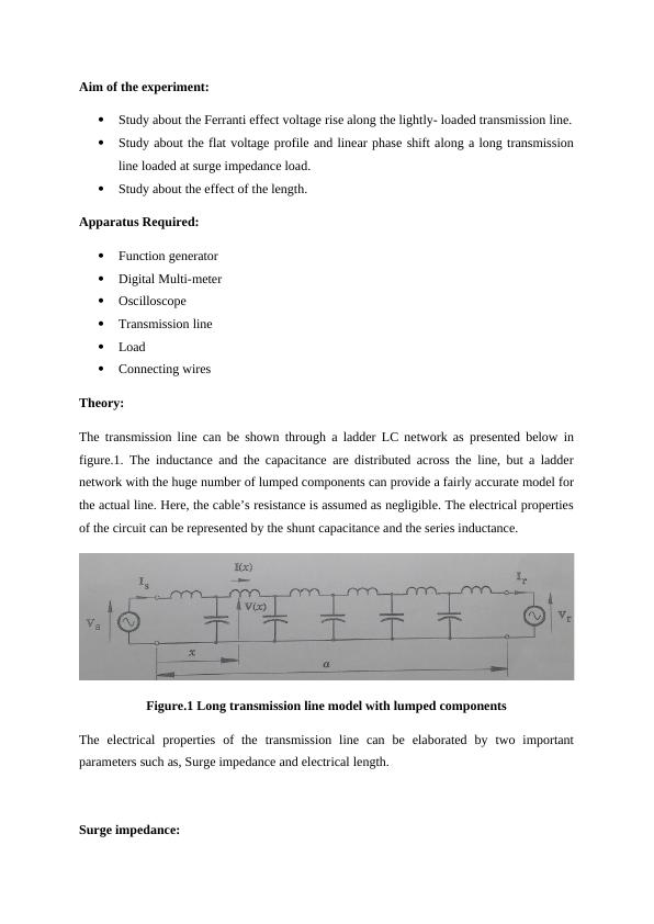
The transmission line can be shown through a ladder LC network as presented below in
figure.1. The inductance and the capacitance are distributed across the line, but a ladder
network with the huge number of lumped components can provide a fairly accurate model for
the actual line. Here, the cable’s resistance is assumed as negligible. The electrical properties
of the circuit can be represented by the shunt capacitance and the series inductance.
Figure.1 Long transmission line model with lumped components
The electrical properties of the transmission line can be elaborated by two important
parameters such as, Surge impedance and electrical length.
Surge impedance:
Study about the Ferranti effect voltage rise along the lightly- loaded transmission line.
Study about the flat voltage profile and linear phase shift along a long transmission
line loaded at surge impedance load.
Study about the effect of the length.
Apparatus Required:
Function generator
Digital Multi-meter
Oscilloscope
Transmission line
Load
Connecting wires
Theory:
The transmission line can be shown through a ladder LC network as presented below in
figure.1. The inductance and the capacitance are distributed across the line, but a ladder
network with the huge number of lumped components can provide a fairly accurate model for
the actual line. Here, the cable’s resistance is assumed as negligible. The electrical properties
of the circuit can be represented by the shunt capacitance and the series inductance.
Figure.1 Long transmission line model with lumped components
The electrical properties of the transmission line can be elaborated by two important
parameters such as, Surge impedance and electrical length.
Surge impedance:
The surge impedance is denoted by Z0.
Z0 = √ L
C
Where,
L = Line inductance (in henry)
C = Line Capacitance (in Farad)
In case of formula cancellation, it is possible to use per unit length or per section values.
However, L and C are basically reactive elements but Z0 is a real number. It has the similar
properties as resistance.
Electrical length:
The actual length of the transmission line is calculated in km, but the electrical length of the
transmission line is measured in radians and it can be calculated by,
θ = ω√L.C
Here, it is necessary to use the value of L and C for the whole line.
ω = 2 πf
Here, it is the radian frequency of current and voltage, where f = 50 or 60 Hz (generally)
A line, which is having the value of θ as 2 π can be elaborated as the transmission line with
length of one wavelength at operating frequency f.
Features of transmission line:
When the receiving line of the long transmission line is open circuited, then the voltage
profile across the line can be computed as,
V(x) = Vs
cos(θ (1− x
a ))
cos θ
Where,
x= distance from the sending side
a = Actual length
Vs = Phasor voltage at the sending end
The voltage at the receiving end can be calculated by setting x = a;
Thus;
Vr = V(a) = Vs/ cos θ
The equation determines a problem with the long line as the receiving end voltage Vr exceeds
the sending voltage Vs by the factor of 1/ cos θ. Hence it is too far outside the voltage
acceptable range.
A line with Z0 termination has a flat voltage profile as, V (x) = Vs = Vr.
The power transmitted across this load impedance is the urge impedance load (SIL) and
natural load. If this load is having the higher value than SIL, the voltage profile tends to leg.
If the load value is less than SIL, then the voltage profile tends to rise. SIL is typically
denoted by MW.
Experiment Result:
Model Transmission Line
(a) Given,
L = 7.20mH
C= 0.020μF
Z0 = √ L
C = √ 7.20 × 10⁻³
0.020× 10−6 = 600Ω
(b) Given,
L = 7.20mH
C= 0.020μF
F = 700 Hz
ω = 2 πf = 2 π × 700 = 4398 rad/f
θ = 4398√7.20 ×10−3 × 0.020× 10−6
θ = 0.052776 radians.
For whole line at 10 sections,
θ = 4398√100׿) = 30.2830
Open circuit test
Given,
F = 700 Hz
Vpp = 10 V
Vs(ms) = 3.5 V
Result Table:
Point (Vx) in V Vs(V) Vpu = Vx/Vs (pu)
1 3.61 Vpu = 1/3.61 = 0.277
2 3.70 Vpu = 2/ 3.70 = 0.540
3 3.78 Vpu = 3/3.78 = 0.794
4 3.86 Vpu = 4/3.86 = 1.036
5 3.92 Vpu = 5/ 3.92 = 1.276
6 3.97 Vpu = 6/ 3.97 = 1.511
7 4.01 Vpu = 7/4.01 = 1.746
8 4.04 Vpu = 8/4.04 = 1.980
9 4.06 Vpu = 9/4.06 = 2.217
10 4.06 Vpu = 10/ 4.06 = 2.463
End of preview
Want to access all the pages? Upload your documents or become a member.
Related Documents
Electrical Powerlg...
|14
|2073
|306
Power System Analysis Part 2 .lg...
|16
|1740
|475
Synchronous Generator and Short Transmission Line Circuit Analysislg...
|10
|697
|73
The Propagation Constant Solution 2022lg...
|22
|556
|29
Electronics And Electrical Power Assignmentlg...
|5
|537
|28
1). The following Z transform mathematical expression hlg...
|9
|415
|43