Air Recirculation Through a Duct-Room System
VerifiedAdded on 2022/02/07
|10
|1811
|52
AI Summary
This paper is based on Air Recirculation Through a Duct-Room System. The goal of this lab was to evaluate air flow into a room, analyse heat losses during heating and cooling, and calculate the amount of electricity required by pre-heaters during operation, as well as explain the various reasons of the aforementioned events. Two tests, A and B, were carried out. Air was allowed to flow into the room via a duct and into the outlet in test A, but not into the room via a recirculated system in test B.
Contribute Materials
Your contribution can guide someone’s learning journey. Share your
documents today.
Air Recirculation Through a Duct-Room System
Abstract
The purpose of this laboratory was to examine air flow into a room and analyze the heat losses
during heating and cooling and the power consumed by the pre-heaters during operation and
explain the possible causes for the phenomena above. Two test A and B were conducted. In test
A, air was allowed to flow into the room via a duct and into the outlet whereas in test B. air was
allowed to flow into the room via a recirculated system. In test A, the inlet and the outlet louvres
were open while the recycle louvre was closed. On the other hand, in test B the inlet and the
outlet louvres were closed and only the recycle louvre was operational. The velocity of air
flowing into the room and the temperatures were measured using velocity meters and
temperature sensors respectively. It was observed that the temperatures were higher for test B
where a recirculated system was used compared to test A for there was no recirculation.
Nomenclature
Contents
Abstract..........................................................................................................................................1
Nomenclature.................................................................................................................................1
Introduction....................................................................................................................................1
Methodology...................................................................................................................................3
Equipment’s Used......................................................................................................................3
Experimental Set-up..................................................................................................................4
Assumptions................................................................................................................................5
Secure Best Marks with AI Grader
Need help grading? Try our AI Grader for instant feedback on your assignments.
Procedure....................................................................................................................................5
Test A..........................................................................................................................................6
Test B...........................................................................................................................................6
Results and Analysis......................................................................................................................6
Conclusion......................................................................................................................................8
List of Tables
List of Figures
Introduction
Heat transfer is the process by which energy is transferred from a medium of low temperature to
a medium of high temperature. The various forms of heat transfer are conduction, convection,
and radiation. The study of heat transfer aids in the analysis of thermodynamic processes such as
flow of air in a room and its efficiency.
In this experiment, heat flow from one end to the other end of an enclosed assembled system is
determined to simulate what would happen in a real environment. Heat transfer between two
surfaces is determined using the following equation:
∆ QAB =m(CpB T B−C pA T A )
The mass flow rate “m” is determined as follows:
m=ρV =ρ Ac V avg ( Kgm−3 )
The specific heat is determined by the equation;
C p= 28.11+0.1967 x 10⁻² T + 0.4802 x 10⁻⁵ T 2−0.1966 x 10⁻⁹ T3
28.97
Where T is the temperature in Kelvin and Cp is in KJ/Kg.K.
Air density is determined using the formula below;
P
ρ =RT
The power produced by the pre-heater is determined using the equation below:
Power=mC p (T 1−T 2)
In this experiment two tests A and B were conducted. In test A, an inlet and outlet louvre were
open whereas the recycle louvre was closed to ensure that no air got back into the system and
that all the air that came in via the inlet went out via the outlet. On the other hand, in test B, the
inlet and outlet were shut and the recycle louvre left open to ensure that instead of the air leaving
the room, it was just circulated inside.
Methodology
Equipment’s Used
To combination of equipment’s used to successful completion of the experiment were; the
velocity meters, the temperatures sensors, the fan, the pre-heaters, recirculation duct. All this
equipment’s were assembled into a single unit that was controlled by RA3-360 computer
software that read the values from the temperature and velocity sensors. The speed of the fan and
the power to pre-heaters were also adjusted by the computer software. A side view of the entire
system is as shown below:

Air will flow from the inlet to the outlet for test A, and as it flows it will first be filtered to ensure
only clean air gets in. Then it will be heated at instances to compensate for the heat lost as it
flows form the inlet to the out let. Temperatures placed strategically within the system will
measure the temperature. Moreover, the velocity of the air getting in and out of the system will
be determined by use of velocity meters placed near the inlet and the outlet. In test B, the inlets
and the outlets will be closed and only the recycle louvre will be operational. Again, the
temperatures and the velocity will be determined and recorded on the computer software.
Experimental Set-up
Secure Best Marks with AI Grader
Need help grading? Try our AI Grader for instant feedback on your assignments.
The equipment above was used for simulation purpose. Air got into the system via the inlet
louver through a transparent duct. The transparency of the duct facilitated visibility. A controller
on the surface of the system was used to control the opening and closing of the system for air
flow. Other components in the system were; computer controlled pre-heaters to heat the inlet air
set at 40% and 60%, a computer controlled fan of fixed speed, temperature sensor for
measurement of temperature getting in and out of the duct and filters to ensure that only clean air
got into the system.
The temperature sensors were placed at specified distances along the system. Temperature sensor
T1 was placed at the inlet, while T2 was placed on the other end of the duct after the first set of
preheaters to measure the temperature in the pipe. Due to the presence of the preheaters, the
temperature T2 was greater than T1. After T2 another temperature sensor T3 existed to measure
before it got into the room. Again, preheaters were used to heat air between T2 and T3 so as to
compensate for the heat lost as the air travelled through the duct. Temperature sensor T4
measured the temperature just before it exited into the room and temperature sensor T5 measured
the temperature from the room. Temperature T5 was less than T4 since the warm air from T4 had
lost some of its energy before it got into the room.
Two velocity sensors V1 and V2 were installed at the inlet and the outlet of the system to
measure the velocity of the incoming and outgoing air. Recycle louvre was installed at the inlet
to allow reentry of air into the system from the external environment. The whole system was
connected to a computer via the RA3-306 Air condition software.
Assumptions
Assumptions were made to ensure efficiency of the system and hence the accuracy of the results
were of high quality and reliable. The assumptions were; the flow of air was uniform throughout
the system, temperature was equally distributed in the system, the air in the experiment was dry
and that the specific heat for air and temperature was different and the ideal density of the gas
was used.
Procedure
Before any test is conducted, the initial step is to ensure safety and precaution measures are
followed. The system is then switched on and then its connected to the computer software.
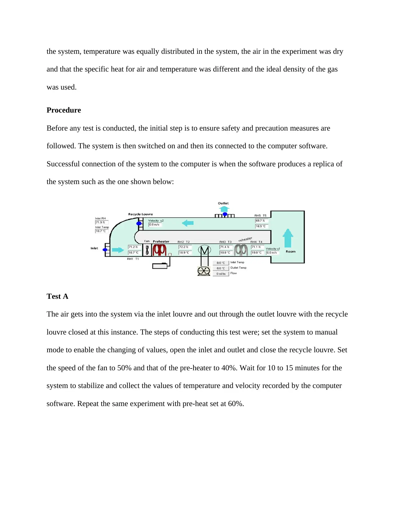
Successful connection of the system to the computer is when the software produces a replica of
the system such as the one shown below:
Test A
The air gets into the system via the inlet louvre and out through the outlet louvre with the recycle
louvre closed at this instance. The steps of conducting this test were; set the system to manual
mode to enable the changing of values, open the inlet and outlet and close the recycle louvre. Set
the speed of the fan to 50% and that of the pre-heater to 40%. Wait for 10 to 15 minutes for the
system to stabilize and collect the values of temperature and velocity recorded by the computer
software. Repeat the same experiment with pre-heat set at 60%.
and that the specific heat for air and temperature was different and the ideal density of the gas
was used.
Procedure
Before any test is conducted, the initial step is to ensure safety and precaution measures are
followed. The system is then switched on and then its connected to the computer software.
Successful connection of the system to the computer is when the software produces a replica of
the system such as the one shown below:
Test A
The air gets into the system via the inlet louvre and out through the outlet louvre with the recycle
louvre closed at this instance. The steps of conducting this test were; set the system to manual
mode to enable the changing of values, open the inlet and outlet and close the recycle louvre. Set
the speed of the fan to 50% and that of the pre-heater to 40%. Wait for 10 to 15 minutes for the
system to stabilize and collect the values of temperature and velocity recorded by the computer
software. Repeat the same experiment with pre-heat set at 60%.
Test B
The air gets into the system via the recirculation duct. In this case the inlet and the outlet were
closed. The steps of conducting this test were; set the system to manual mode to enable shift of
variables, close the inlet and outlet and open the recirculation duct. Set the speed of the fan to
50% and that of the pre-heater to 40%. Wait for 10 to 15 minutes for the system to stabilize and
collect the values of temperature and velocity recorded by the computer software. Repeat the
same experiment with pre-heat set at 60%.
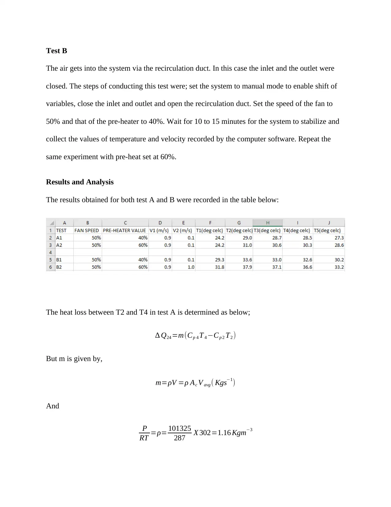
Results and Analysis
The results obtained for both test A and B were recorded in the table below:
The heat loss between T2 and T4 in test A is determined as below;
∆ Q24 =m(Cp 4 T 4 −Cp 2 T2 )
But m is given by,
m=ρV =ρ Ac V avg ( Kgs−1)
And
P
RT =ρ= 101325
287 X 302=1.16 Kgm−3
The air gets into the system via the recirculation duct. In this case the inlet and the outlet were
closed. The steps of conducting this test were; set the system to manual mode to enable shift of
variables, close the inlet and outlet and open the recirculation duct. Set the speed of the fan to
50% and that of the pre-heater to 40%. Wait for 10 to 15 minutes for the system to stabilize and
collect the values of temperature and velocity recorded by the computer software. Repeat the
same experiment with pre-heat set at 60%.
Results and Analysis
The results obtained for both test A and B were recorded in the table below:
The heat loss between T2 and T4 in test A is determined as below;
∆ Q24 =m(Cp 4 T 4 −Cp 2 T2 )
But m is given by,
m=ρV =ρ Ac V avg ( Kgs−1)
And
P
RT =ρ= 101325
287 X 302=1.16 Kgm−3
Paraphrase This Document
Need a fresh take? Get an instant paraphrase of this document with our AI Paraphraser
Hence,
m=ρV =ρ Ac V avg ( Kgs−1 ) =1.16 X 0.9 x 0.04=0.041 Kgs−1
The specific heat is the same for all the temperatures and is calculated using the following;
C p= 28.11+0.1967 x 10⁻² (302)+0.4802 x 10⁻⁵ (302)2−0.1966 x 10⁻⁹ (302)3
28.97
¿ 29.41
28.29 =1.00 KJ per Kg∗K
The value of heat loss between T2 and T4 is thus determined as follows:
∆ Q24 =m(Cp 4 T 4 −Cp 2 T2 )
¿ 0.041 ( 301.5−302 )=−0.020 KJ /s
Heat loss between T4 and T5 in test A is given by;
∆ Q45=m(Cp 5 T5 −Cp 4 T 4 )
¿ 0.041 ( 300.5−301.5 ) =−0.041 KJ /s
The calculations for power produced by the pre-heater in test A follows and are as below with
the assumption that there is no heat loss between temperature sensors T1 and T2.
Power=mC p (T 1−T 2)
¿ 0.041 X 1.00 (302−297.2 )=0.17 KW
The heat losses between T5 and T1 in test B are calculated as follows;
∆ Q51=m(C p 5 T 5−C p 1 T 1)
¿ 0.041 ( 303.2−304.8 )=−0.065 KJ /s
The heat gains between T4 and T5 for test B is as follows;
∆ Q45=m(Cp 4 T 4 −Cp 5 T5 )
¿ 0.041 ( 305.6−303.2 ) =0.098 KJ /s
The power for pre-heaters in test B was determined using the equation below;
Power=mC p (T 1−T 2)
¿ 0.041 X 1.00 ( 306 .6−302.3 ) =0.19 KW
Conclusion
The temperature sensor T2 was obtaining heat from the pre-heater, hence its value was much
higher than the other temperature sensors. The heat loss was from region of high temperature to
the region of low temperature hence it occurred from T2. Situation where heat loss occurred the
value of change for heat has a negative value while where heat gain occurred has a positive
value. The temperatures in Test B were much higher than those of Test A due to heat absorbed
during recirculation and also the internal heat that came up with the recycled air.
In terms of power consumption, it is evident that more power was consumed in test B than in test
A indicating that the pre-heater supplied more power to the recirculation duct in test B.
Moreover, in test B recycled was used and required more power for artificial circulation.
Errors were experienced in the system and can be attributed to the following factors. First, the
inlet louvre and the outlet louvre may have not been perfectly opened in test A or perfectly
closed in test B meaning unwanted air may have got in or escaped from the system. Moreover,
the system may have not been perfectly insulated, meaning there could have been heat gain or

heat loss via conduction and radiation from the system. Other possible errors in the system were,
failure of the computer software to stabilize and approximation errors in calculation.
failure of the computer software to stabilize and approximation errors in calculation.
1 out of 10
Related Documents


Your All-in-One AI-Powered Toolkit for Academic Success.
+13062052269
info@desklib.com
Available 24*7 on WhatsApp / Email
![[object Object]](/_next/static/media/star-bottom.7253800d.svg)
Unlock your academic potential
© 2024 | Zucol Services PVT LTD | All rights reserved.