Medical Appointment Booking System Design
VerifiedAdded on 2020/03/28
|17
|2174
|257
AI Summary
This assignment delves into the design of a comprehensive medical appointment booking system. It presents various aspects of the system, such as user interactions, workflow processes, and data models. The document utilizes activity diagrams, sequence diagrams, class diagrams, and state diagrams to illustrate the system's functionality. Reports on patient details and appointments are also included, providing insights into the system's capabilities.
Contribute Materials
Your contribution can guide someone’s learning journey. Share your
documents today.

Student details
Secure Best Marks with AI Grader
Need help grading? Try our AI Grader for instant feedback on your assignments.
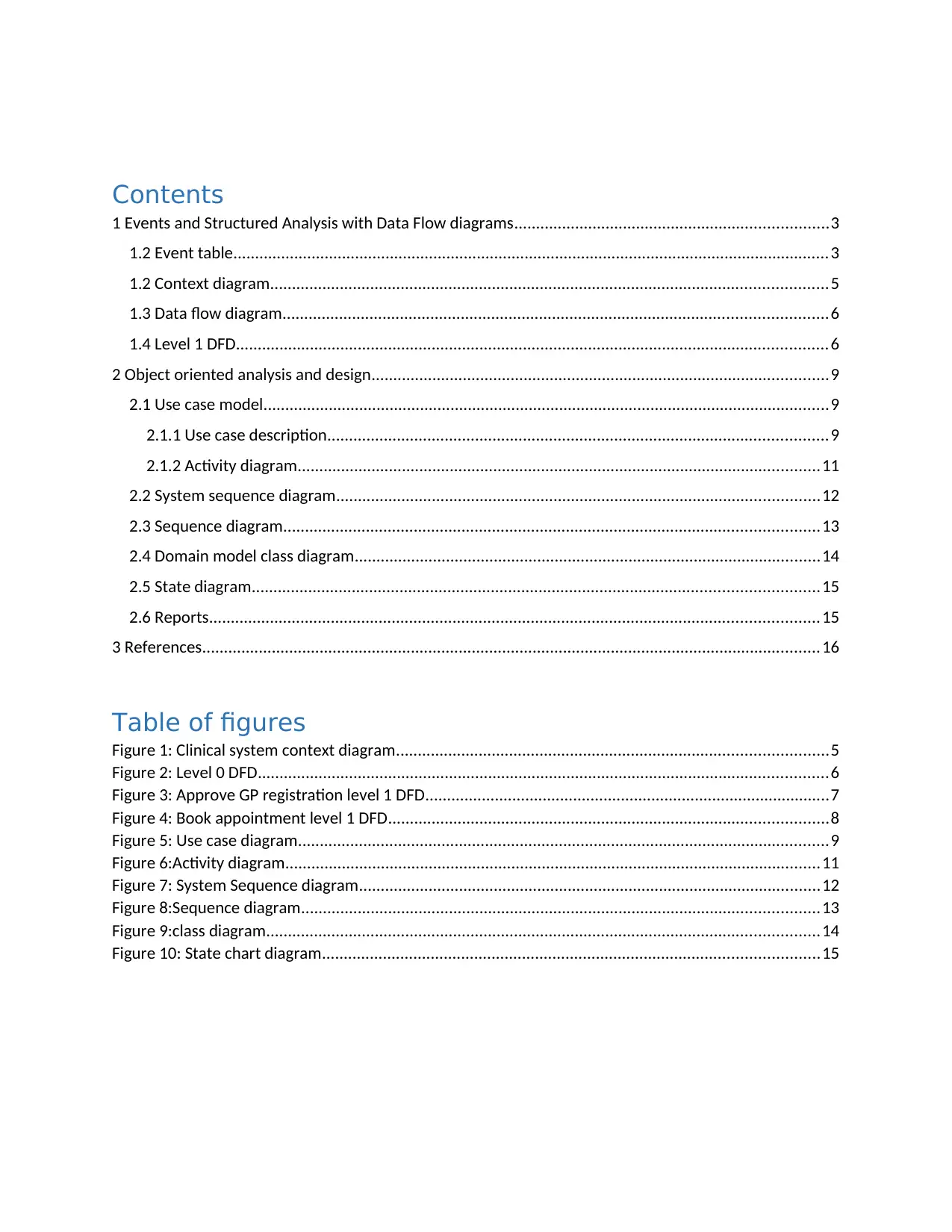
Contents
1 Events and Structured Analysis with Data Flow diagrams........................................................................3
1.2 Event table.........................................................................................................................................3
1.2 Context diagram................................................................................................................................5
1.3 Data flow diagram.............................................................................................................................6
1.4 Level 1 DFD........................................................................................................................................6
2 Object oriented analysis and design.........................................................................................................9
2.1 Use case model..................................................................................................................................9
2.1.1 Use case description...................................................................................................................9
2.1.2 Activity diagram........................................................................................................................11
2.2 System sequence diagram...............................................................................................................12
2.3 Sequence diagram...........................................................................................................................13
2.4 Domain model class diagram...........................................................................................................14
2.5 State diagram..................................................................................................................................15
2.6 Reports............................................................................................................................................15
3 References..............................................................................................................................................16
Table of figures
Figure 1: Clinical system context diagram...................................................................................................5
Figure 2: Level 0 DFD...................................................................................................................................6
Figure 3: Approve GP registration level 1 DFD.............................................................................................7
Figure 4: Book appointment level 1 DFD.....................................................................................................8
Figure 5: Use case diagram..........................................................................................................................9
Figure 6:Activity diagram...........................................................................................................................11
Figure 7: System Sequence diagram..........................................................................................................12
Figure 8:Sequence diagram.......................................................................................................................13
Figure 9:class diagram...............................................................................................................................14
Figure 10: State chart diagram..................................................................................................................15
1 Events and Structured Analysis with Data Flow
diagrams
1.2 Event table
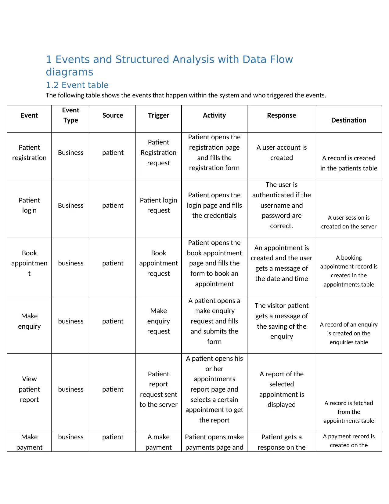
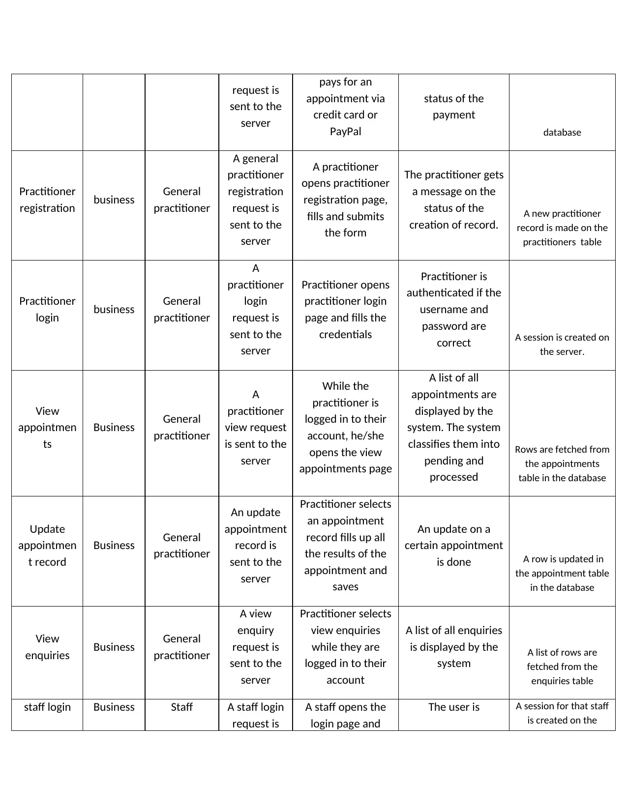
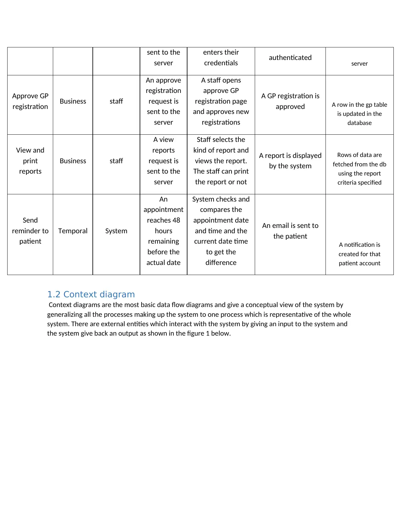
The following table shows the events that happen within the system and who triggered the events.
Event Event
Type Source Trigger Activity Response Destination
Patient
registration Business patient
Patient
Registration
request
Patient opens the
registration page
and fills the
registration form
A user account is
created A record is created
in the patients table
Patient
login Business patient Patient login
request
Patient opens the
login page and fills
the credentials
The user is
authenticated if the
username and
password are
correct.
A user session is
created on the server
Book
appointmen
t
business patient
Book
appointment
request
Patient opens the
book appointment
page and fills the
form to book an
appointment
An appointment is
created and the user
gets a message of
the date and time
A booking
appointment record is
created in the
appointments table
Make
enquiry business patient
Make
enquiry
request
A patient opens a
make enquiry
request and fills
and submits the
form
The visitor patient
gets a message of
the saving of the
enquiry
A record of an enquiry
is created on the
enquiries table
View
patient
report
business patient
Patient
report
request sent
to the server
A patient opens his
or her
appointments
report page and
selects a certain
appointment to get
the report
A report of the
selected
appointment is
displayed A record is fetched
from the
appointments table
Make
payment
business patient A make
payment
Patient opens make
payments page and
Patient gets a
response on the
A payment record is
created on the
request is
sent to the
server
pays for an
appointment via
credit card or
PayPal
status of the
payment
database
Practitioner
registration business General
practitioner
A general
practitioner
registration
request is
sent to the
server
A practitioner
opens practitioner
registration page,
fills and submits
the form
The practitioner gets
a message on the
status of the
creation of record. A new practitioner
record is made on the
practitioners table
Practitioner
login business General
practitioner
A
practitioner
login
request is
sent to the
server
Practitioner opens
practitioner login
page and fills the
credentials
Practitioner is
authenticated if the
username and
password are
correct A session is created on
the server.
View
appointmen
ts
Business General
practitioner
A
practitioner
view request
is sent to the
server
While the
practitioner is
logged in to their
account, he/she
opens the view
appointments page
A list of all
appointments are
displayed by the
system. The system
classifies them into
pending and
processed
Rows are fetched from
the appointments
table in the database
Update
appointmen
t record
Business General
practitioner
An update
appointment
record is
sent to the
server
Practitioner selects
an appointment
record fills up all
the results of the
appointment and
saves
An update on a
certain appointment
is done A row is updated in
the appointment table
in the database
View
enquiries Business General
practitioner
A view
enquiry
request is
sent to the
server
Practitioner selects
view enquiries
while they are
logged in to their
account
A list of all enquiries
is displayed by the
system A list of rows are
fetched from the
enquiries table
staff login Business Staff A staff login
request is
A staff opens the
login page and
The user is A session for that staff
is created on the
sent to the
server
pays for an
appointment via
credit card or
PayPal
status of the
payment
database
Practitioner
registration business General
practitioner
A general
practitioner
registration
request is
sent to the
server
A practitioner
opens practitioner
registration page,
fills and submits
the form
The practitioner gets
a message on the
status of the
creation of record. A new practitioner
record is made on the
practitioners table
Practitioner
login business General
practitioner
A
practitioner
login
request is
sent to the
server
Practitioner opens
practitioner login
page and fills the
credentials
Practitioner is
authenticated if the
username and
password are
correct A session is created on
the server.
View
appointmen
ts
Business General
practitioner
A
practitioner
view request
is sent to the
server
While the
practitioner is
logged in to their
account, he/she
opens the view
appointments page
A list of all
appointments are
displayed by the
system. The system
classifies them into
pending and
processed
Rows are fetched from
the appointments
table in the database
Update
appointmen
t record
Business General
practitioner
An update
appointment
record is
sent to the
server
Practitioner selects
an appointment
record fills up all
the results of the
appointment and
saves
An update on a
certain appointment
is done A row is updated in
the appointment table
in the database
View
enquiries Business General
practitioner
A view
enquiry
request is
sent to the
server
Practitioner selects
view enquiries
while they are
logged in to their
account
A list of all enquiries
is displayed by the
system A list of rows are
fetched from the
enquiries table
staff login Business Staff A staff login
request is
A staff opens the
login page and
The user is A session for that staff
is created on the
Secure Best Marks with AI Grader
Need help grading? Try our AI Grader for instant feedback on your assignments.
sent to the
server
enters their
credentials authenticated server
Approve GP
registration Business staff
An approve
registration
request is
sent to the
server
A staff opens
approve GP
registration page
and approves new
registrations
A GP registration is
approved A row in the gp table
is updated in the
database
View and
print
reports
Business staff
A view
reports
request is
sent to the
server
Staff selects the
kind of report and
views the report.
The staff can print
the report or not
A report is displayed
by the system
Rows of data are
fetched from the db
using the report
criteria specified
Send
reminder to
patient
Temporal System
An
appointment
reaches 48
hours
remaining
before the
actual date
System checks and
compares the
appointment date
and time and the
current date time
to get the
difference
An email is sent to
the patient
A notification is
created for that
patient account
1.2 Context diagram
Context diagrams are the most basic data flow diagrams and give a conceptual view of the system by
generalizing all the processes making up the system to one process which is representative of the whole
system. There are external entities which interact with the system by giving an input to the system and
the system give back an output as shown in the figure 1 below.
server
enters their
credentials authenticated server
Approve GP
registration Business staff
An approve
registration
request is
sent to the
server
A staff opens
approve GP
registration page
and approves new
registrations
A GP registration is
approved A row in the gp table
is updated in the
database
View and
reports
Business staff
A view
reports
request is
sent to the
server
Staff selects the
kind of report and
views the report.
The staff can print
the report or not
A report is displayed
by the system
Rows of data are
fetched from the db
using the report
criteria specified
Send
reminder to
patient
Temporal System
An
appointment
reaches 48
hours
remaining
before the
actual date
System checks and
compares the
appointment date
and time and the
current date time
to get the
difference
An email is sent to
the patient
A notification is
created for that
patient account
1.2 Context diagram
Context diagrams are the most basic data flow diagrams and give a conceptual view of the system by
generalizing all the processes making up the system to one process which is representative of the whole
system. There are external entities which interact with the system by giving an input to the system and
the system give back an output as shown in the figure 1 below.
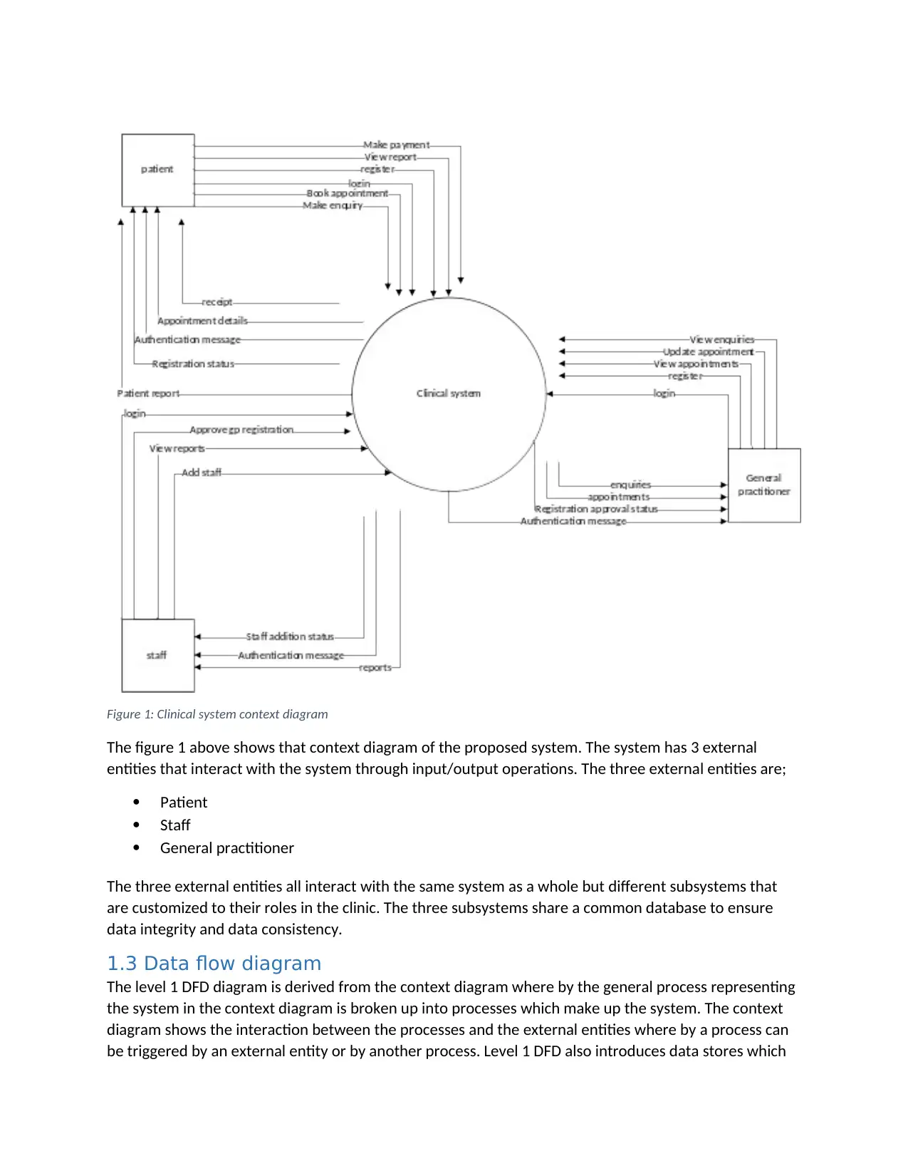
Figure 1: Clinical system context diagram
The figure 1 above shows that context diagram of the proposed system. The system has 3 external
entities that interact with the system through input/output operations. The three external entities are;
Patient
Staff
General practitioner
The three external entities all interact with the same system as a whole but different subsystems that
are customized to their roles in the clinic. The three subsystems share a common database to ensure
data integrity and data consistency.
1.3 Data flow diagram
The level 1 DFD diagram is derived from the context diagram where by the general process representing
the system in the context diagram is broken up into processes which make up the system. The context
diagram shows the interaction between the processes and the external entities where by a process can
be triggered by an external entity or by another process. Level 1 DFD also introduces data stores which
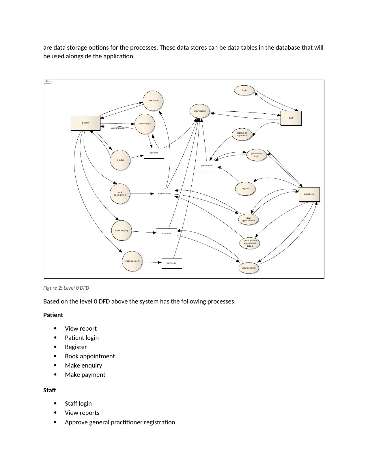
are data storage options for the processes. These data stores can be data tables in the database that will
be used alongside the application.
dfd c
patient loginpatient
patients
register
book
appointment appointments
make enquiry
enquiries
view report
make payment
payments
practitioner
practitioner
login
practitioners
register
view
appointments
update patient
appointment
details
view enquiries
staff
login
approve gp
registration
view reports
authentication
Figure 2: Level 0 DFD
Based on the level 0 DFD above the system has the following processes;
Patient
View report
Patient login
Register
Book appointment
Make enquiry
Make payment
Staff
Staff login
View reports
Approve general practitioner registration
Paraphrase This Document
Need a fresh take? Get an instant paraphrase of this document with our AI Paraphraser
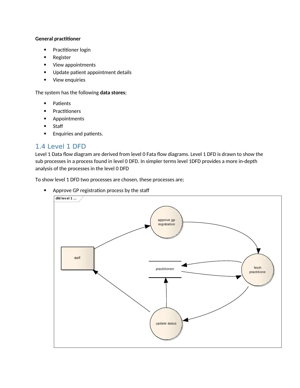
General practitioner
Practitioner login
Register
View appointments
Update patient appointment details
View enquiries
The system has the following data stores;
Patients
Practitioners
Appointments
Staff
Enquiries and patients.
1.4 Level 1 DFD
Level 1 Data flow diagram are derived from level 0 Fata flow diagrams. Level 1 DFD is drawn to show the
sub processes in a process found in level 0 DFD. In simpler terms level 1DFD provides a more in-depth
analysis of the processes in the level 0 DFD
To show level 1 DFD two processes are chosen, these processes are;
Approve GP registration process by the staff
dfd lev el 1 ...
staff
approve gp
registration
practitioners fetch
practitioner
update status
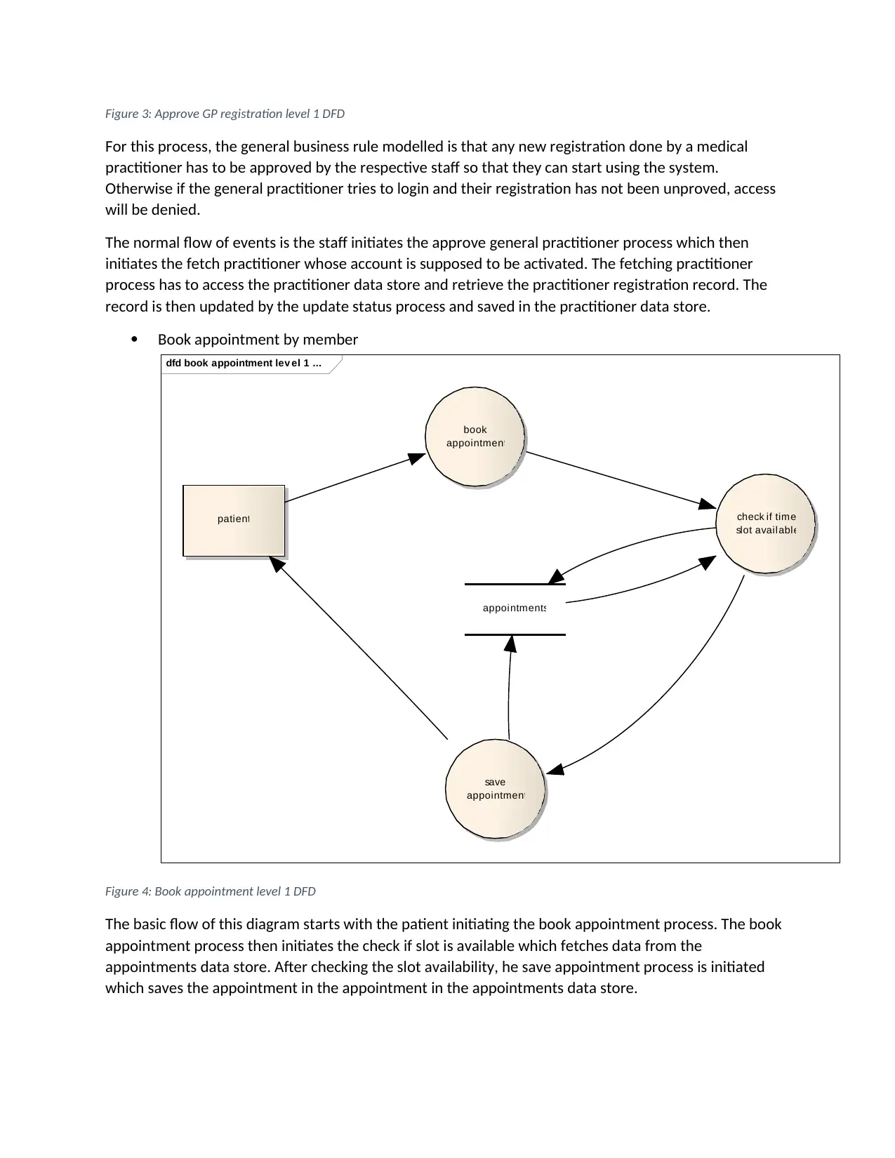
Figure 3: Approve GP registration level 1 DFD
For this process, the general business rule modelled is that any new registration done by a medical
practitioner has to be approved by the respective staff so that they can start using the system.
Otherwise if the general practitioner tries to login and their registration has not been unproved, access
will be denied.
The normal flow of events is the staff initiates the approve general practitioner process which then
initiates the fetch practitioner whose account is supposed to be activated. The fetching practitioner
process has to access the practitioner data store and retrieve the practitioner registration record. The
record is then updated by the update status process and saved in the practitioner data store.
Book appointment by member
dfd book appointment lev el 1 ...
patient
book
appointment
appointments
check if time
slot available
save
appointment
Figure 4: Book appointment level 1 DFD
The basic flow of this diagram starts with the patient initiating the book appointment process. The book
appointment process then initiates the check if slot is available which fetches data from the
appointments data store. After checking the slot availability, he save appointment process is initiated
which saves the appointment in the appointment in the appointments data store.
2 Object oriented analysis and design
2.1 Use case model
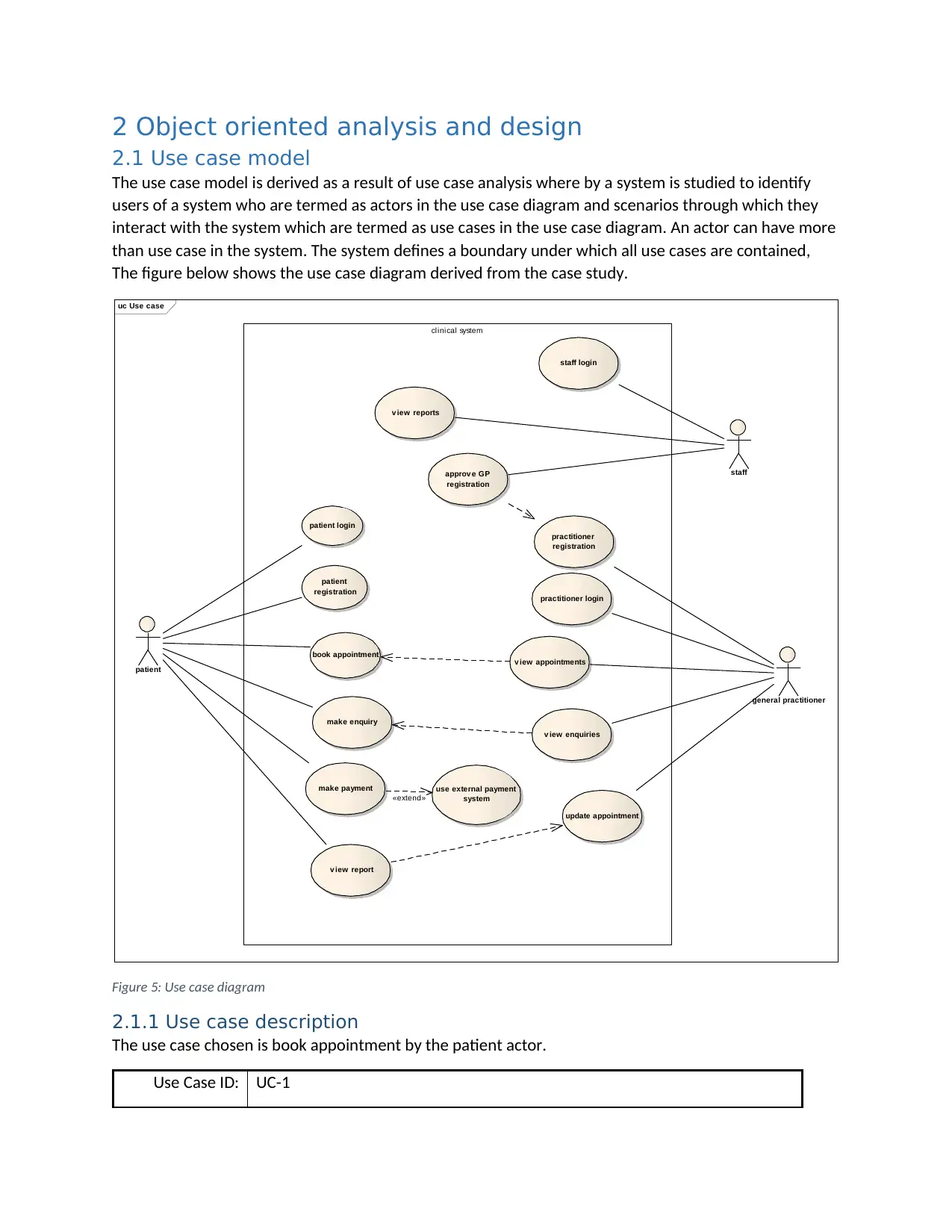
The use case model is derived as a result of use case analysis where by a system is studied to identify
users of a system who are termed as actors in the use case diagram and scenarios through which they
interact with the system which are termed as use cases in the use case diagram. An actor can have more
than use case in the system. The system defines a boundary under which all use cases are contained,
The figure below shows the use case diagram derived from the case study.
uc Use case
clinical system
patient
patient login
patient
registration
book appointment
make enquiry
make payment
v iew report
use external payment
system
general practitioner
practitioner login
practitioner
registration
v iew appointments
update appointment
v iew enquiries
staff
staff login
approv e GP
registration
v iew reports
«extend»
Figure 5: Use case diagram
2.1.1 Use case description
The use case chosen is book appointment by the patient actor.
Use Case ID: UC-1
Secure Best Marks with AI Grader
Need help grading? Try our AI Grader for instant feedback on your assignments.
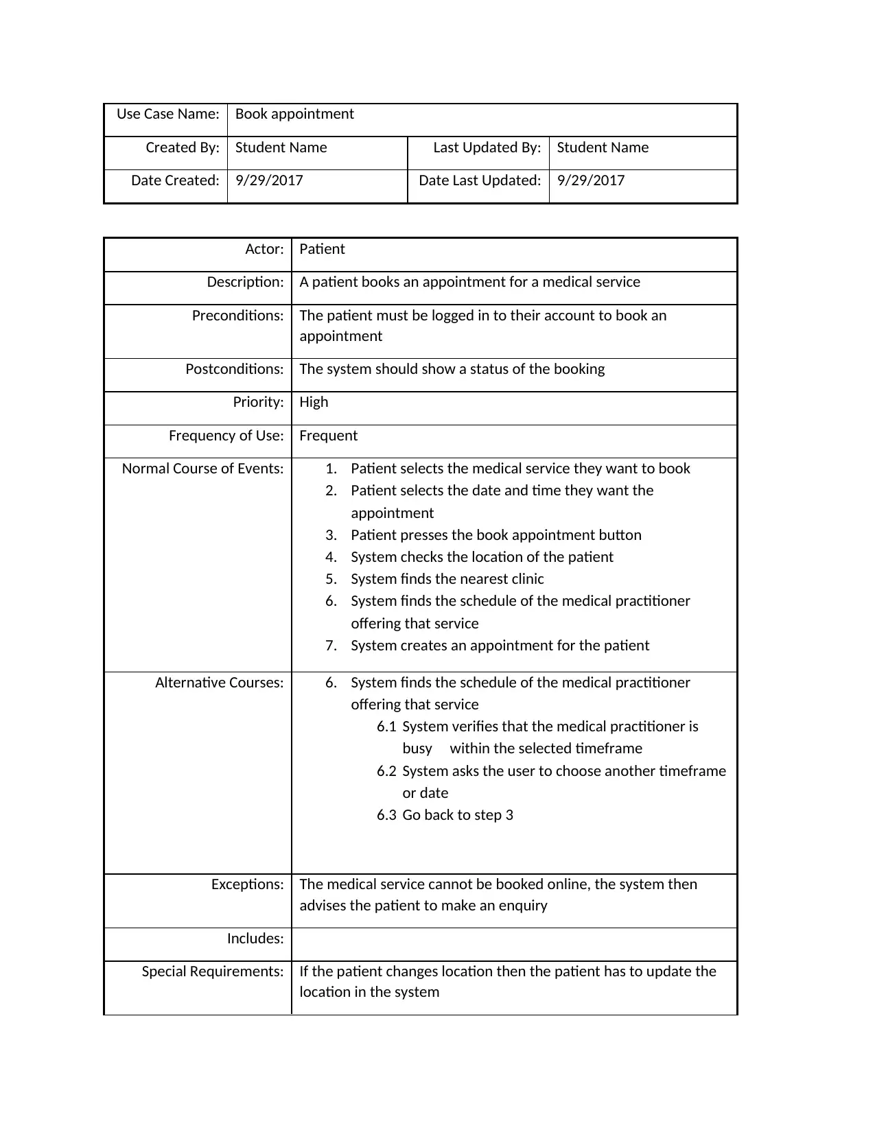
Use Case Name: Book appointment
Created By: Student Name Last Updated By: Student Name
Date Created: 9/29/2017 Date Last Updated: 9/29/2017
Actor: Patient
Description: A patient books an appointment for a medical service
Preconditions: The patient must be logged in to their account to book an
appointment
Postconditions: The system should show a status of the booking
Priority: High
Frequency of Use: Frequent
Normal Course of Events: 1. Patient selects the medical service they want to book
2. Patient selects the date and time they want the
appointment
3. Patient presses the book appointment button
4. System checks the location of the patient
5. System finds the nearest clinic
6. System finds the schedule of the medical practitioner
offering that service
7. System creates an appointment for the patient
Alternative Courses: 6. System finds the schedule of the medical practitioner
offering that service
6.1 System verifies that the medical practitioner is
busy within the selected timeframe
6.2 System asks the user to choose another timeframe
or date
6.3 Go back to step 3
Exceptions: The medical service cannot be booked online, the system then
advises the patient to make an enquiry
Includes:
Special Requirements: If the patient changes location then the patient has to update the
location in the system
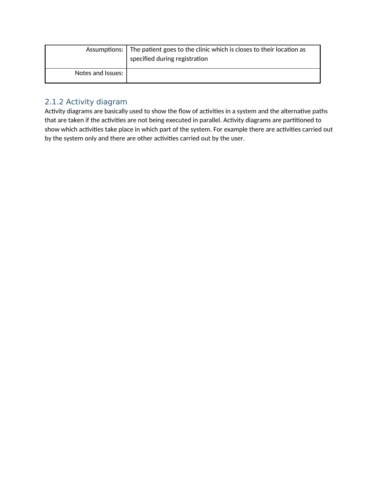
Assumptions: The patient goes to the clinic which is closes to their location as
specified during registration
Notes and Issues:
2.1.2 Activity diagram
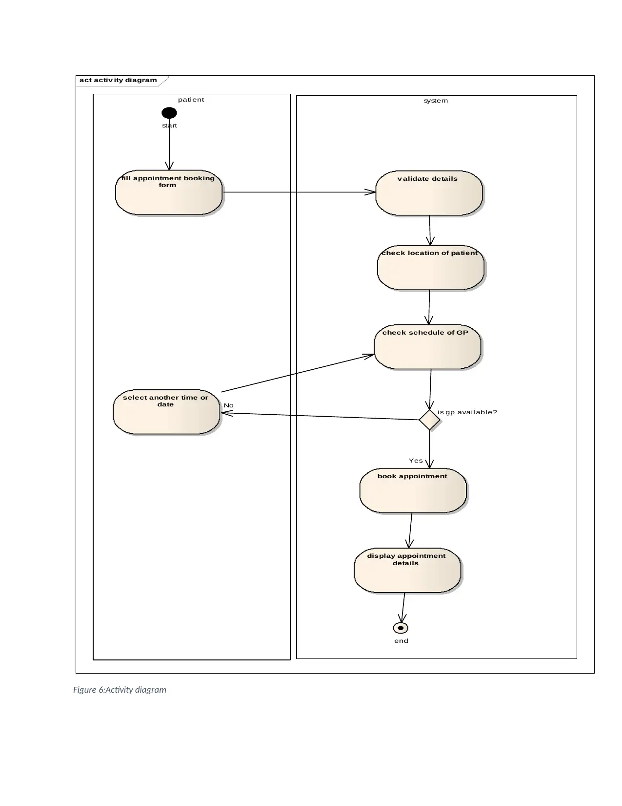
Activity diagrams are basically used to show the flow of activities in a system and the alternative paths
that are taken if the activities are not being executed in parallel. Activity diagrams are partitioned to
show which activities take place in which part of the system. For example there are activities carried out
by the system only and there are other activities carried out by the user.
act activ ity diagram
systempatient
fill appointment booking
form
start
v alidate details
check location of patient
check schedule of GP
book appointment
is gp available?
select another time or
date
display appointment
details
end
No
Yes
Figure 6:Activity diagram
systempatient
fill appointment booking
form
start
v alidate details
check location of patient
check schedule of GP
book appointment
is gp available?
select another time or
date
display appointment
details
end
No
Yes
Figure 6:Activity diagram
Paraphrase This Document
Need a fresh take? Get an instant paraphrase of this document with our AI Paraphraser
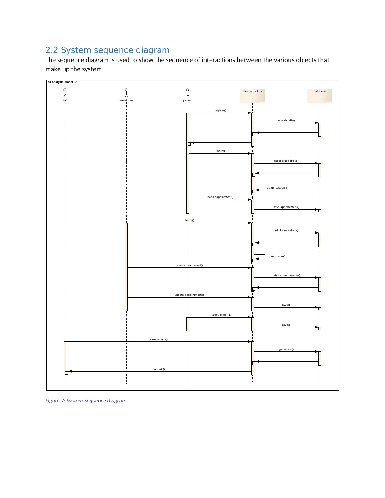
2.2 System sequence diagram
The sequence diagram is used to show the sequence of interactions between the various objects that
make up the system
sd Analysis Model
staff practitioner patient
clinical system database
register()
save details()
login()
cehck credentials()
create session()
book appointment()
save appointment()
login()
cehck credentials()
create sesion()
view appointment()
fetch appointments()
update appointments()
save()
make payment()
save()
view reports()
get report()
reports()
Figure 7: System Sequence diagram
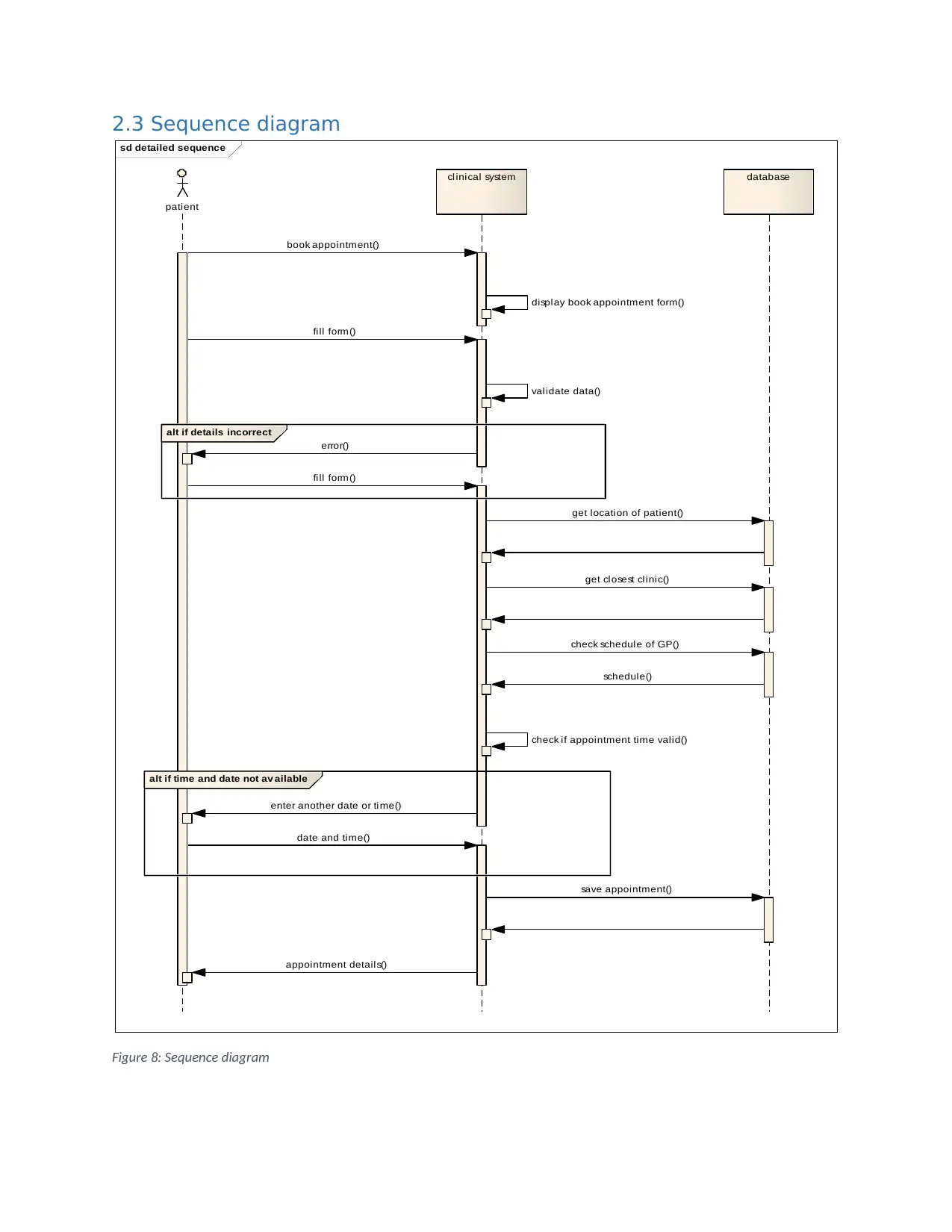
2.3 Sequence diagram
sd detailed sequence
patient
clinical system database
alt if details incorrect
alt if time and date not av ailable
book appointment()
display book appointment form()
fill form()
validate data()
error()
fill form()
get location of patient()
get closest clinic()
check schedule of GP()
schedule()
check if appointment time valid()
enter another date or time()
date and time()
save appointment()
appointment details()
Figure 8: Sequence diagram
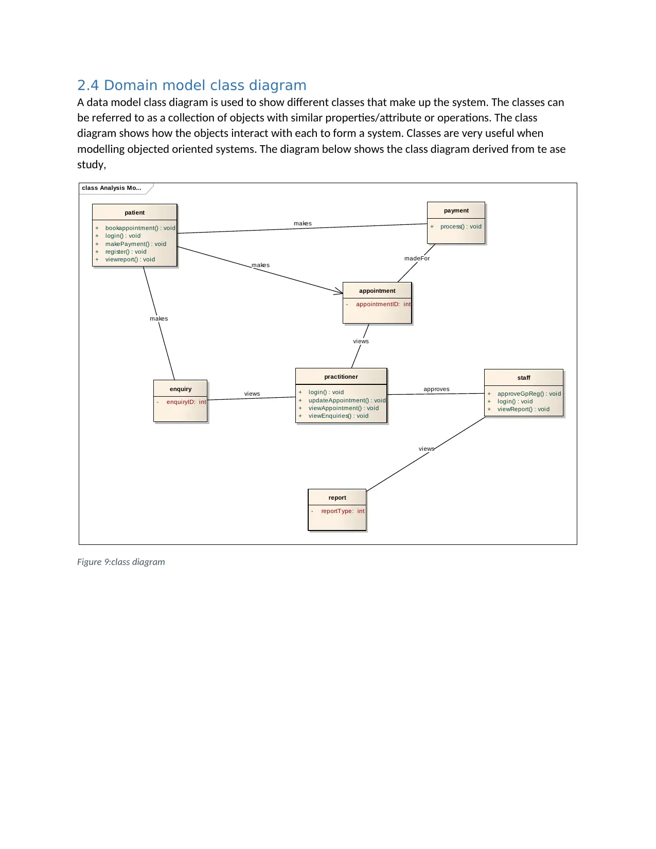
2.4 Domain model class diagram
A data model class diagram is used to show different classes that make up the system. The classes can
be referred to as a collection of objects with similar properties/attribute or operations. The class
diagram shows how the objects interact with each to form a system. Classes are very useful when
modelling objected oriented systems. The diagram below shows the class diagram derived from te ase
study,
class Analysis Mo...
patient
+ bookappointment() : void
+ login() : void
+ makePayment() : void
+ register() : void
+ viewreport() : void
appointment
- appointmentID: int
practitioner
+ login() : void
+ updateAppointment() : void
+ viewAppointment() : void
+ viewEnquiries() : void
enquiry
- enquiryID: int
staff
+ approveGpReg() : void
+ login() : void
+ viewReport() : void
report
- reportType: int
payment
+ process() : void
makes
views
makes
views approves
views
makes
madeFor
Figure 9:class diagram
Secure Best Marks with AI Grader
Need help grading? Try our AI Grader for instant feedback on your assignments.
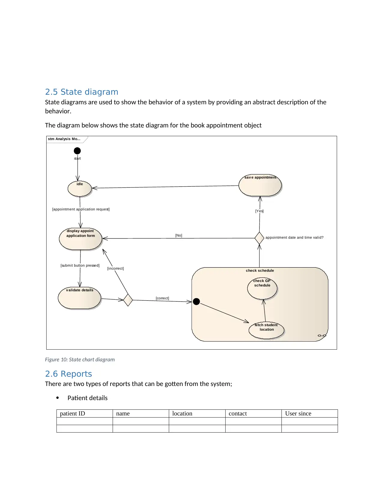
2.5 State diagram
State diagrams are used to show the behavior of a system by providing an abstract description of the
behavior.
The diagram below shows the state diagram for the book appointment object
stm Analysis Mo...
start
idle
display appoint
application form
v alidate details
check schedule
fetch student
location
check GP
schedule
appointment date and time valid?
sav e appointment
[appointment application request]
[submit button pressed] [incorrect]
[correct]
[No]
[Yes]
Figure 10: State chart diagram
2.6 Reports
There are two types of reports that can be gotten from the system;
Patient details
patient ID name location contact User since
1 out of 17
Related Documents
Your All-in-One AI-Powered Toolkit for Academic Success.
+13062052269
info@desklib.com
Available 24*7 on WhatsApp / Email
![[object Object]](/_next/static/media/star-bottom.7253800d.svg)
Unlock your academic potential
© 2024 | Zucol Services PVT LTD | All rights reserved.


