Stress Analysis in Cylindrical Shell

Verified

Added on  2019/09/23

|10
|467
|172
Project
AI Summary
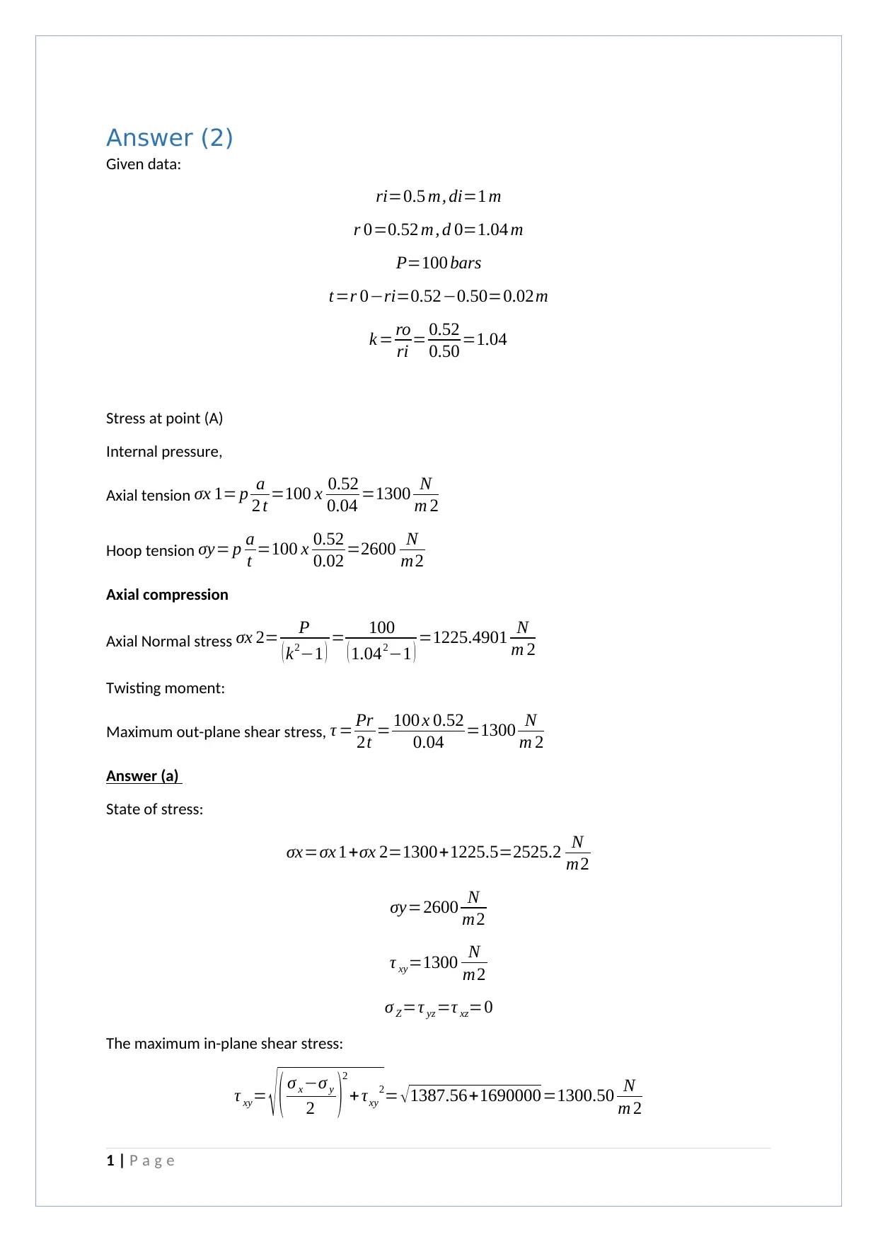
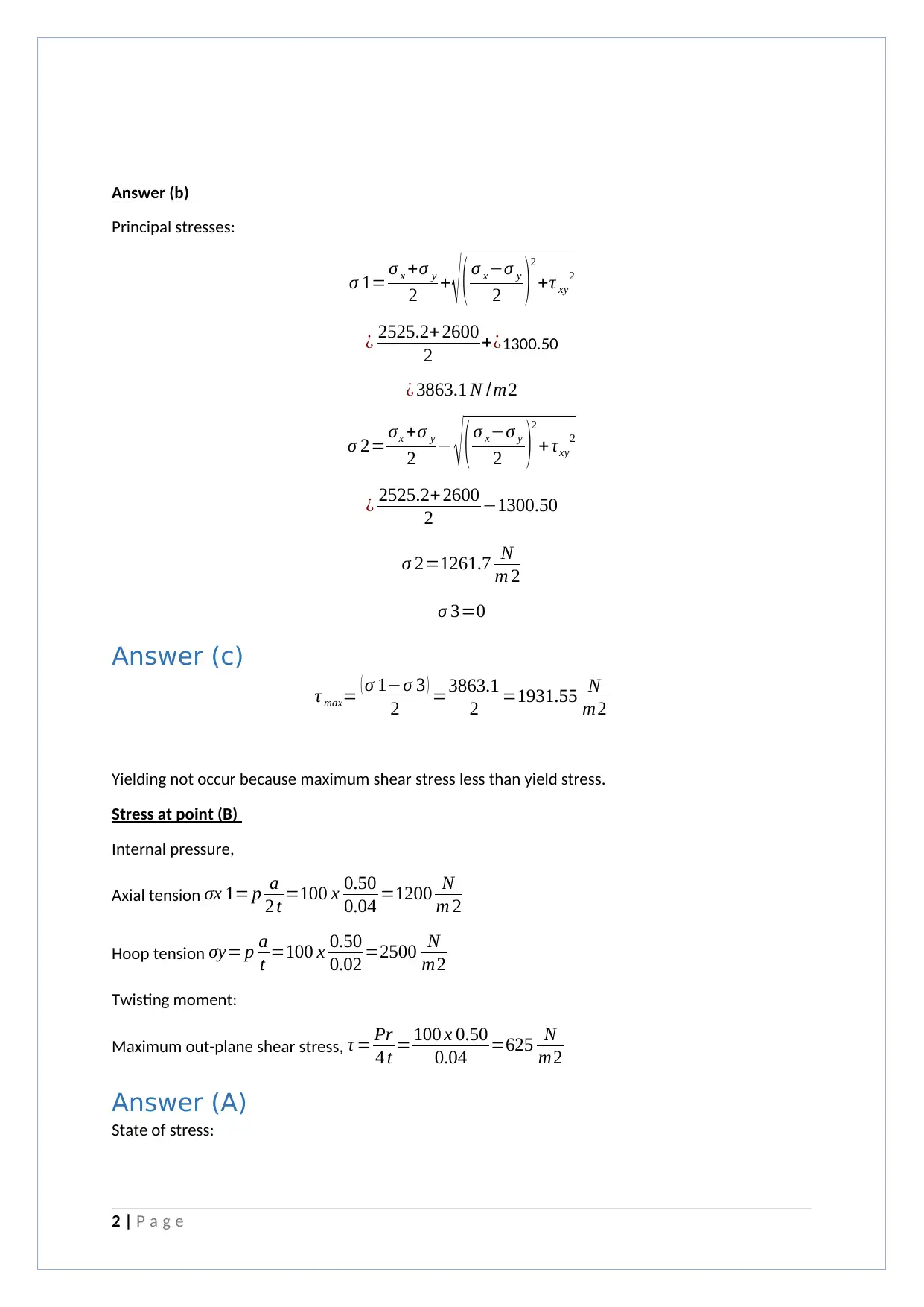
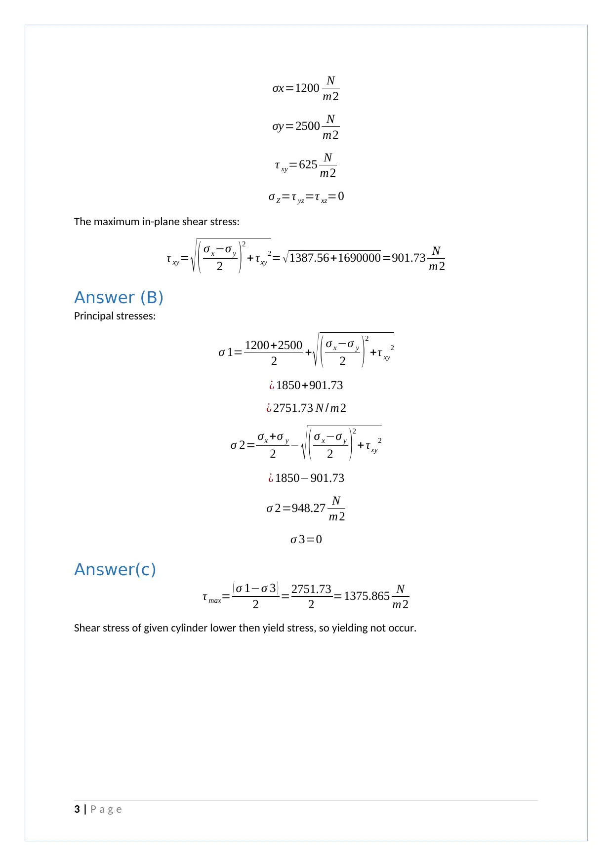
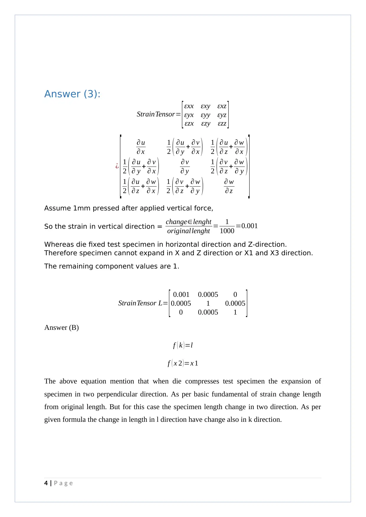
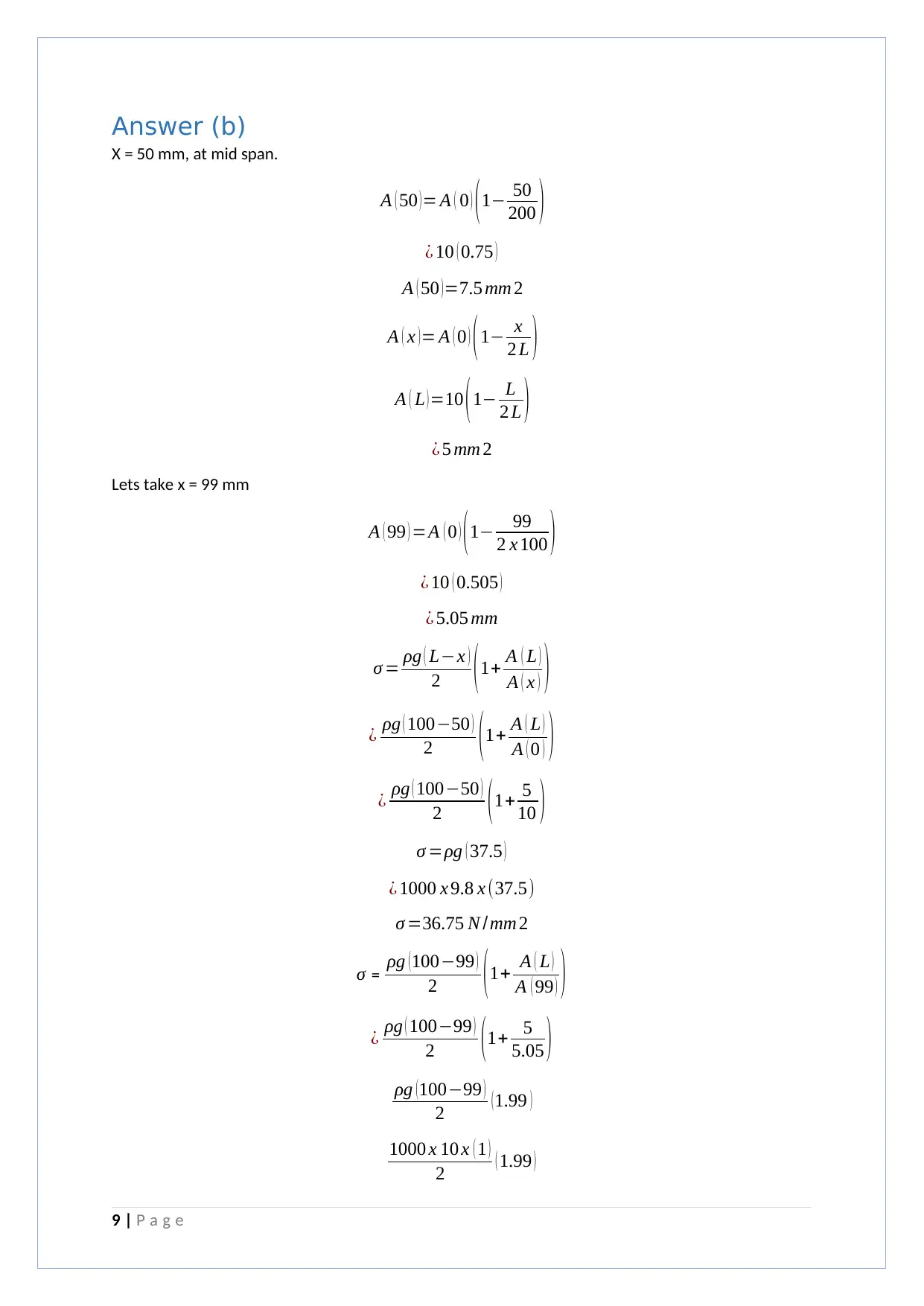
The assignment content discusses various concepts in solid mechanics, including stress at points A and B, principal stresses, and strain. It also includes a problem involving the finite element method to calculate displacement and stress. The summary is as follows: Points A and B are under internal pressure, axial tension, and hoop tension with no twisting moment. The maximum out-of-plane shear stress is lower than the yield stress, so yielding does not occur. Assuming a 1mm compression after applying a vertical force, the strain in the vertical direction is calculated. The finite element method is used to calculate displacement and stress for a given problem.
tabler-icon-diamond-filled.svg

Contribute Materials

Your contribution can guide someone’s learning journey. Share your documents today.
Document Page
Answer (2)
Given data:
ri=0.5 m, di=1 m
r 0=0.52 m, d 0=1.04 m
P=100 bars
t=r 0ri=0.520.50=0.02m
k = ro
ri = 0.52
0.50 =1.04
Stress at point (A)
Internal pressure,
Axial tension σx 1= p a
2 t =100 x 0.52
0.04 =1300 N
m 2
Hoop tension σy= p a
t =100 x 0.52
0.02 =2600 N
m2
Axial compression
Axial Normal stress σx 2= P
( k21 ) = 100
( 1.0421 ) =1225.4901 N
m 2
Twisting moment:
Maximum out-plane shear stress, τ = Pr
2t = 100 x 0.52
0.04 =1300 N
m 2
Answer (a)
State of stress:
σx=σx 1+σx 2=1300+1225.5=2525.2 N
m2
σy=2600 N
m2
τ xy=1300 N
m2
σ Z=τ yz =τ xz=0
The maximum in-plane shear stress:
τ xy= ( σ xσ y
2 )2
+ τxy
2= 1387.56+1690000=1300.50 N
m 2
1 | P a g e
tabler-icon-diamond-filled.svg

Secure Best Marks with AI Grader

Need help grading? Try our AI Grader for instant feedback on your assignments.
Document Page
Answer (b)
Principal stresses:
σ 1= σ x +σ y
2 + ( σ xσ y
2 )2
+τ xy
2
¿ 2525.2+ 2600
2 +¿1300.50
¿ 3863.1 N /m2
σ 2= σx +σ y
2 ( σ xσ y
2 )2
+ τxy
2
¿ 2525.2+2600
2 1300.50
σ 2=1261.7 N
m 2
σ 3=0
Answer (c)
τ max= ( σ 1σ 3 )
2 =3863.1
2 =1931.55 N
m2
Yielding not occur because maximum shear stress less than yield stress.
Stress at point (B)
Internal pressure,
Axial tension σx 1= p a
2 t =100 x 0.50
0.04 =1200 N
m 2
Hoop tension σy= p a
t =100 x 0.50
0.02 =2500 N
m2
Twisting moment:
Maximum out-plane shear stress, τ = Pr
4 t = 100 x 0.50
0.04 =625 N
m2
Answer (A)
State of stress:
2 | P a g e
Document Page
σx=1200 N
m2
σy=2500 N
m2
τ xy=625 N
m2
σ Z=τ yz =τ xz=0
The maximum in-plane shear stress:
τ xy= ( σ xσ y
2 )2
+ τxy
2= 1387.56+1690000=901.73 N
m2
Answer (B)
Principal stresses:
σ 1= 1200+2500
2 + ( σ xσ y
2 )
2
+τ xy
2
¿ 1850+901.73
¿ 2751.73 N / m2
σ 2= σx +σ y
2 ( σ xσ y
2 )2
+ τxy
2
¿ 1850901.73
σ 2=948.27 N
m2
σ 3=0
Answer(c)
τ max= ( σ 1σ 3 )
2 =2751.73
2 =1375.865 N
m2
Shear stress of given cylinder lower then yield stress, so yielding not occur.
3 | P a g e
Document Page
Answer (3):
StrainTensor= [εxx εxy εxz
εyx εyy εyz
εzx εzy εzz ]
¿
[ u
x
1
2 ( u
y + v
x ) 1
2 ( u
z + w
x )
1
2 ( u
y + v
x ) v
y
1
2 ( v
z + w
y )
1
2 ( u
z + w
x ) 1
2 ( v
z + w
y ) w
z ]Assume 1mm pressed after applied vertical force,
So the strain in vertical direction = changelenght
originallenght = 1
1000 =0.001
Whereas die fixed test specimen in horizontal direction and Z-direction.
Therefore specimen cannot expand in X and Z direction or X1 and X3 direction.
The remaining component values are 1.
StrainTensor L= [ 0.001 0.0005 0
0.0005 1 0.0005
0 0.0005 1 ]
Answer (B)
f ( k ) =l
f ( x 2 )=x 1
The above equation mention that when die compresses test specimen the expansion of
specimen in two perpendicular direction. As per basic fundamental of strain change length
from original length. But for this case the specimen length change in two direction. As per
given formula the change in length in l direction have change also in k direction.
4 | P a g e
tabler-icon-diamond-filled.svg

Secure Best Marks with AI Grader

Need help grading? Try our AI Grader for instant feedback on your assignments.
Document Page
[ u
x 1
1
2 ( u
x 2 + v
x 1 ) 1
2 ( u
x 3 + w
x 1 )
1
2 ( u
x 2 + v
x 1 ) v
x 2
1
2 ( v
x 3 + w
x 2 )
1
2 ( u
x 3 + w
x 1 ) 1
2 ( v
x 3 + w
x 2 ) w
x 3
]let us consider u=l , v=kw=n
¿
[ l
x 1
1
2 ( l
x 2 + k
x 1 ) 1
2 ( l
x 3 + n
x 1 )
1
2 ( l
x 2 + k
x 1 ) k
x 2
1
2 ( k
x 3 + n
x 2 )
1
2 ( l
x 3 + n
x 1 ) 1
2 ( k
x 3 + n
x 2 ) n
x 3
]
¿
[ 1
l
1
2 (0+ 1
l ) 1
2 ( 0+0 )
1
2 (0+ 1
l ) 1
k
1
2 ( 0+0 )
1
2 ( 0+0 ) 1
2 ( 0+0 ) 0 ]
¿
[ 1
l
1
2l 0
1
2l
1
k 0
0 0 0 ]
For compressive stress σ =
σ com=E
[ 1
l
1
2l 0
1
2l
1
k 0
0 0 0 ] N /mm2
5 | P a g e
Document Page
Answer (C)
As given m = 9500mm so the change in length = 500mm so that following strain
tensor obtained
ε = 500
1000 =0.5
Following matrix obtained
ε ij= [ 0.5 0.25 0.25
0.25 1 0
0.25 0 1 ]
σ =ε ij E
Converting into meter and obtained following equation
¿ 1000 x [ 0.5 0.25 0.25
0.25 1 0
0.25 0 1 ]
σ ij= [ 500 250 250
250 1000 0
0 25 1000 ] N /mm 2
F=σ x 1 x 1 x Area
Fx 1 x 1=500 x ( 10 x 10 )
Fx 1 x 1=50000 N
Answer (4):
Using two element each of 50 mm long in length, the finite element model in figure below. Nodes
and elements are numbered as shown. Noted that the area at the mid-point of the plate is as
discussed following:
6 | P a g e
Document Page
A ( x )= A ( 0 ) (1 x
2 L )
A 1 ( 0 )=10 mm2
L=100 mm
Let us take area X = L,
A ( L )=10 (1 1
2 )
A 2 ( L )=5 mm 2
So, the area at mid span A 3= A 1+ A 2
2 =10+5
2 = 7.5mm2
Area of top most ¿ position= 10+7.5
2 =8.75 mm 2
Area of bottom most position= 7.5+5
2 =6.25 mm 2
Boundary condition F 1=0 , F 3=1 N
Element stiffness matrix Ke= EA
L [ 1 1
1 1 ]
K1= 1000 x 8.75
50 [ 1 1
1 1 ]
K2= 1000 x 6.25
50 [ 1 1
1 1 ]
The global stiffness matrix K assembled
K= 1000
50 [ 1 8.75 0
8.75 15 6.25
0 6.25 6.25 ]
The element body force vector are
Fe= Alρ
2 [1
1 ]
F1= 8.75 x 50 x 1000
2 [1
1 ]
F2=6.25 x 50 x 1000
2 [ 1
1 ]
7 | P a g e
tabler-icon-diamond-filled.svg

Paraphrase This Document

Need a fresh take? Get an instant paraphrase of this document with our AI Paraphraser
Document Page
The force applied
F1= 8.75 x 50 x 1000
2 [1
1 ]
F1=[ 0.218750
0.218750 ]
F2=6.25 x 50 x 1000
2 [ 1
1 ]
F2=
[0.156250
0.156250 ]
The global load vector F is assembled from f 1 , f 2 and the point load F = 1N added
F= [ 0.218750
0.37500
1.15625 ]
Now using formula in order to obtained displacement F=kx
1000
50 [ 1 8.75 0
8.75 15 6.25
0 6.25 6.25 ][u 1
u 2
u 3 ]= [0.218750
0.37500
1.15625 ]
sinceu 1=0 due ¿ ¿ postion of vertical rod , eliminate first rawfirst coloum
1000 x 6.25
50 [ 15 6.25
6.25 6.25 ][u 2
u3 ]= [ 0.375
1.15625 ]
Solving above ¿
u 2=1.4 mm
u 3=3.35952 mm
To obtain stress
σ =EBq
σ 1=1000 x 1
50 [ 1 1 ] [ 0
1.4 ] =28 N
mm 2
σ 2=1000 x 1
50 [ 1 1 ] [ 1.4
3.35952 ]=39.1904 N
mm 2
8 | P a g e
Document Page
Answer (b)
X = 50 mm, at mid span.
A ( 50 ) = A ( 0 ) ( 1 50
200 )
¿ 10 ( 0.75 )
A ( 50 )=7.5 mm 2
A ( x )= A ( 0 ) (1 x
2 L )
A ( L )=10 (1 L
2 L )
¿ 5 mm 2
Lets take x = 99 mm
A ( 99 ) =A ( 0 ) (1 99
2 x 100 )
¿ 10 ( 0.505 )
¿ 5.05 mm
σ = ρg ( Lx )
2 ( 1+ A ( L )
A ( x ) )
¿ ρg ( 10050 )
2 ( 1+ A ( L )
A ( 0 ) )
¿ ρg ( 10050 )
2 (1+ 5
10 )
σ =ρg ( 37.5 )
¿ 1000 x 9.8 x (37.5)
σ =36.75 N / mm 2
σ = ρg (10099 )
2 (1+ A ( L )
A ( 99 ) )
¿ ρg ( 10099 )
2 ( 1+ 5
5.05 )
ρg (10099 )
2 (1.99 )
1000 x 10 x ( 1 )
2 ( 1.99 )
9 | P a g e
Document Page
σ =99.50 N /mm 2
The finite element method and other calculative method have different answer because finite
element consider behaviour at the element level whereas number of elements increasing more
accurate results obtained. In calculative method considering entire body and so that results may
varies from finite element method.
10 | P a g e
chevron_up_icon
1 out of 10
circle_padding
hide_on_mobile
zoom_out_icon
[object Object]

Your All-in-One AI-Powered Toolkit for Academic Success.

Available 24*7 on WhatsApp / Email

[object Object]