Network System Design and Implementation
VerifiedAdded on 2020/11/30
|68
|8283
|427
Project
AI Summary
The assignment focuses on designing and implementing a networked system for a school. It involves analyzing network devices, protocols, and activities. The report details the network design, including wireless connectivity and potential improvements like scaling up the lab and implementing redundant configurations for LAN. Security considerations are also addressed, highlighting the need for firewalls to protect against data breaches.
Contribute Materials
Your contribution can guide someone’s learning journey. Share your
documents today.
ASSIGNMENT FRONT SHEET
Qualification BTEC Level 5 HND Diploma in Computing
Unit number and title Unit 2: Networking
Submission date Date Received 1st submission
Re-submission Date Date Received 2nd submission
Student Name Student ID
Class Assessor name
Student declaration
I certify that the assignment submission is entirely my own work and I fully understand the consequences of plagiarism. I understand that
making a false declaration is a form of malpractice.
Student’s signature LINH
DO THI DIEU LINH
Grading grid
P1 P2 P3 P4 P5 P6 P7 P8 M1 M2 M3 M4 D1 D2 D3
Secure Best Marks with AI Grader
Need help grading? Try our AI Grader for instant feedback on your assignments.
Summative Feedback: Resubmission Feedback:
Grade: Assessor Signature: Date:
Signature & Date:
2
Grade: Assessor Signature: Date:
Signature & Date:
2

3
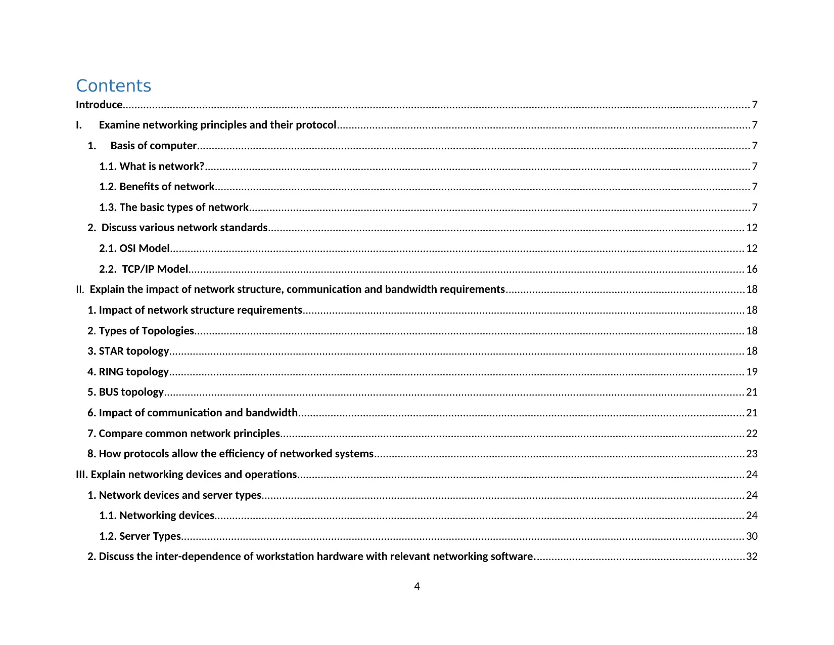
Contents
Introduce..................................................................................................................................................................................................................... 7
I. Examine networking principles and their protocol............................................................................................................................................7
1. Basis of computer............................................................................................................................................................................................ 7
1.1. What is network?......................................................................................................................................................................................... 7
1.2. Benefits of network...................................................................................................................................................................................... 7
1.3. The basic types of network..........................................................................................................................................................................7
2. Discuss various network standards..................................................................................................................................................................12
2.1. OSI Model................................................................................................................................................................................................... 12
2.2. TCP/IP Model............................................................................................................................................................................................. 16
II. Explain the impact of network structure, communication and bandwidth requirements.................................................................................18
1. Impact of network structure requirements......................................................................................................................................................18
2. Types of Topologies........................................................................................................................................................................................... 18
3. STAR topology................................................................................................................................................................................................... 18
4. RING topology................................................................................................................................................................................................... 19
5. BUS topology..................................................................................................................................................................................................... 21
6. Impact of communication and bandwidth.......................................................................................................................................................21
7. Compare common network principles..............................................................................................................................................................22
8. How protocols allow the efficiency of networked systems..............................................................................................................................23
III. Explain networking devices and operations........................................................................................................................................................24
1. Network devices and server types....................................................................................................................................................................24
1.1. Networking devices.................................................................................................................................................................................... 24
1.2. Server Types............................................................................................................................................................................................... 30
2. Discuss the inter-dependence of workstation hardware with relevant networking software.......................................................................32
4
Secure Best Marks with AI Grader
Need help grading? Try our AI Grader for instant feedback on your assignments.
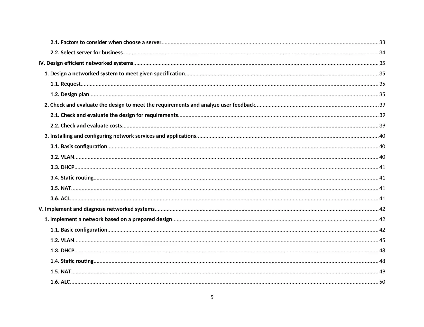
2.1. Factors to consider when choose a server.................................................................................................................................................33
2.2. Select server for business........................................................................................................................................................................... 34
IV. Design efficient networked systems....................................................................................................................................................................35
1. Design a networked system to meet given specification.................................................................................................................................35
1.1. Request....................................................................................................................................................................................................... 35
1.2. Design plan................................................................................................................................................................................................. 35
2. Check and evaluate the design to meet the requirements and analyze user feedback..................................................................................39
2.1. Check and evaluate the design for requirements......................................................................................................................................39
2.2. Check and evaluate costs........................................................................................................................................................................... 39
3. Installing and configuring network services and applications..........................................................................................................................40
3.1. Basis configuration..................................................................................................................................................................................... 40
3.2. VLAN........................................................................................................................................................................................................... 40
3.3. DHCP........................................................................................................................................................................................................... 41
3.4. Static routing.............................................................................................................................................................................................. 41
3.5. NAT............................................................................................................................................................................................................. 41
3.6. ACL.............................................................................................................................................................................................................. 41
V. Implement and diagnose networked systems.....................................................................................................................................................42
1. Implement a network based on a prepared design..........................................................................................................................................42
1.1. Basic configuration..................................................................................................................................................................................... 42
1.2. VLAN........................................................................................................................................................................................................... 45
1.3. DHCP........................................................................................................................................................................................................... 48
1.4. Static routing.............................................................................................................................................................................................. 48
1.5. NAT............................................................................................................................................................................................................. 49
1.6. ALC.............................................................................................................................................................................................................. 50
5
2. Analysis of test result compared with expected results...................................................................................................................................59
2.1. VLAN........................................................................................................................................................................................................... 59
2.2. DHCP........................................................................................................................................................................................................... 60
2.3. Static routing and NAT............................................................................................................................................................................... 61
2.4. ALC.............................................................................................................................................................................................................. 63
2.5. Devices can also ping each other...............................................................................................................................................................63
2.6. Test Mail at network system. Successful...................................................................................................................................................65
2.7. Processing potential improvements for networked systems....................................................................................................................66
Conclude.................................................................................................................................................................................................................... 66
6
Introduce
In the report, I will explain of networking principles, protocols and devices, including benefits and
constraints of networked solutions, the impact of network topology, communication and bandwidth
requirements, effectiveness of networking systems, operating principles of networking devices and server
types and networking software.
I. Examine networking principles and their protocol
1.Basis of computer
1.1. What is network?
A network computer is a group of two and more computer connected together using a
telecommunication system for the purpose of communicating and sharing resources.
1.2. Benefits of network
- File sharing: you can easily share data between different users or remote access if you keep
it on other connected devices. (Audio, Video, Text)
- Resource sharing: using networked peripherals such as printers, scanners and copiers or
sharing software among multiple users, saves money. (printers, network data and
applications can be accessed by remote connection
- devices, using network-connected devices).
- Internet Sharing: it saves costs and can help protect your system if you properly secure the
network. (internet)
- Increasing storage: you can access files and multimedia, such as photos and music, that
you store remotely on other devices or attached storage devices. (NAS – Network Attached
Storage)
1.3. The basic types of network
Based on geographical distance
Computer networks may be distributed in a certain area or may be within a country or
globally. Based on the scope of distribution, one can categorize the following types of
networks:
- LAN (Local Area Network)
7
Paraphrase This Document
Need a fresh take? Get an instant paraphrase of this document with our AI Paraphraser
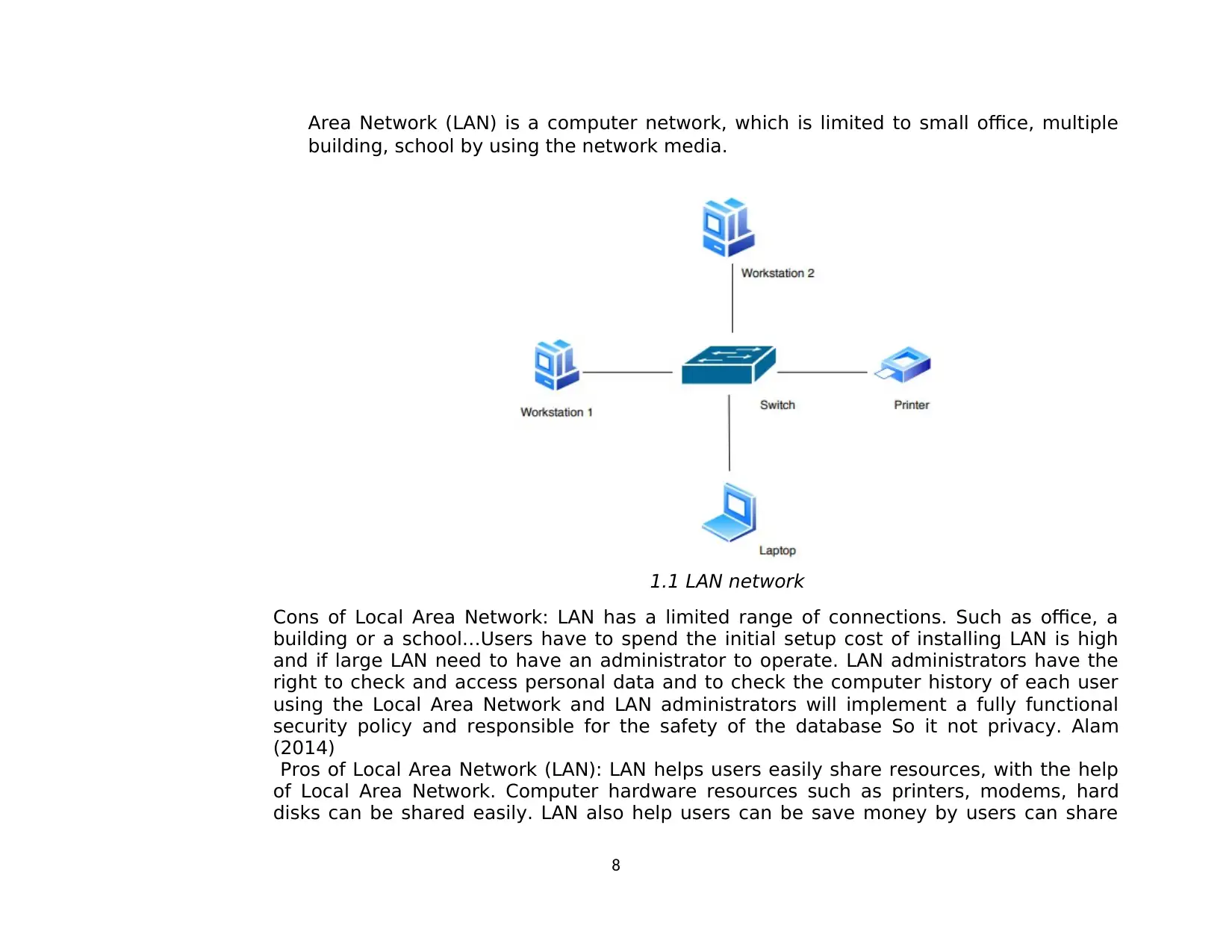
Area Network (LAN) is a computer network, which is limited to small office, multiple
building, school by using the network media.
1.1 LAN network
Cons of Local Area Network: LAN has a limited range of connections. Such as office, a
building or a school…Users have to spend the initial setup cost of installing LAN is high
and if large LAN need to have an administrator to operate. LAN administrators have the
right to check and access personal data and to check the computer history of each user
using the Local Area Network and LAN administrators will implement a fully functional
security policy and responsible for the safety of the database So it not privacy. Alam
(2014)
Pros of Local Area Network (LAN): LAN helps users easily share resources, with the help
of Local Area Network. Computer hardware resources such as printers, modems, hard
disks can be shared easily. LAN also help users can be save money by users can share
8
one application purchased instead of each customer having to buy the application and
only internet connection sharing system keeps the internet costs cheaper. (Alam, 2014).
- Wan (Wide Area Network)
WAN is a computer network connection of wide area such as the world. A Wide
Area Network spans over multiple geographic, which is composed of multiple LANs.
Pros of Metropolitan Area Network (MAN): MAN range of connections is relatively
large, with stable speeds with medium bandwidth to operate applications such as
ATM, cable television, lower installation costs than the global network. The wan
network also meets the security. Requirements. (James Edwards, 2009).
Cons of Metropolitan Area Network (MAN): Wide area network is a data network
designed to connect Metropolitan Area Networks (MAN) between geographically
separated regions, covering both a nation or a global. (Bourgeois, 2016).
9
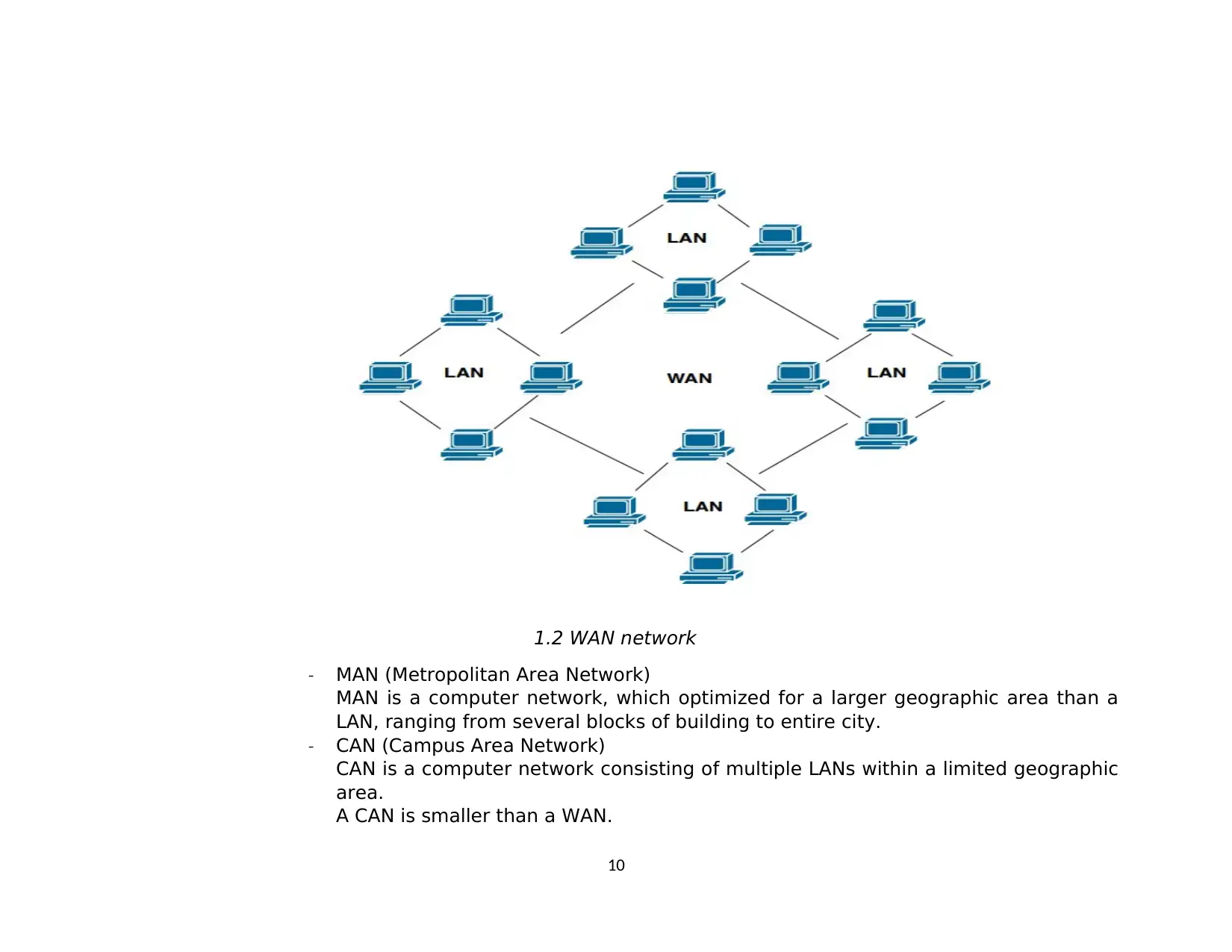
1.2 WAN network
- MAN (Metropolitan Area Network)
MAN is a computer network, which optimized for a larger geographic area than a
LAN, ranging from several blocks of building to entire city.
- CAN (Campus Area Network)
CAN is a computer network consisting of multiple LANs within a limited geographic
area.
A CAN is smaller than a WAN.
10
Secure Best Marks with AI Grader
Need help grading? Try our AI Grader for instant feedback on your assignments.
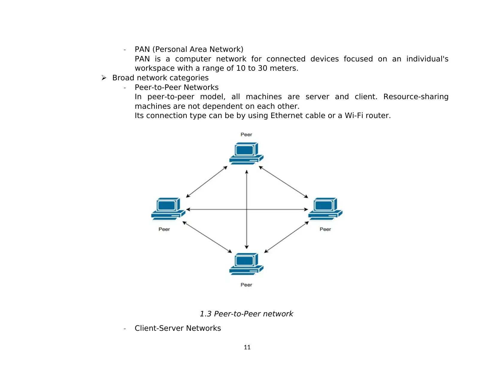
- PAN (Personal Area Network)
PAN is a computer network for connected devices focused on an individual's
workspace with a range of 10 to 30 meters.
Broad network categories
- Peer-to-Peer Networks
In peer-to-peer model, all machines are server and client. Resource-sharing
machines are not dependent on each other.
Its connection type can be by using Ethernet cable or a Wi-Fi router.
1.3 Peer-to-Peer network
- Client-Server Networks
11
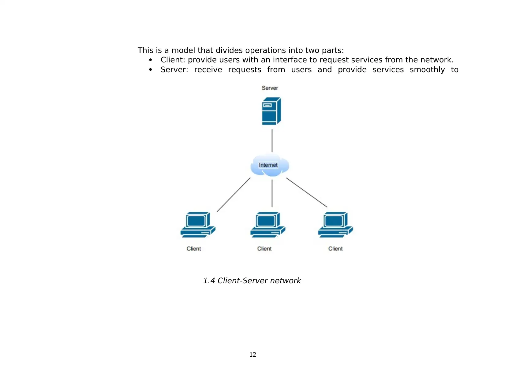
This is a model that divides operations into two parts:
Client: provide users with an interface to request services from the network.
Server: receive requests from users and provide services smoothly to
1.4 Client-Server network
12
Client: provide users with an interface to request services from the network.
Server: receive requests from users and provide services smoothly to
1.4 Client-Server network
12
2. Discuss various network standards
2.1. OSI Model
2.1.1. What is OSI?
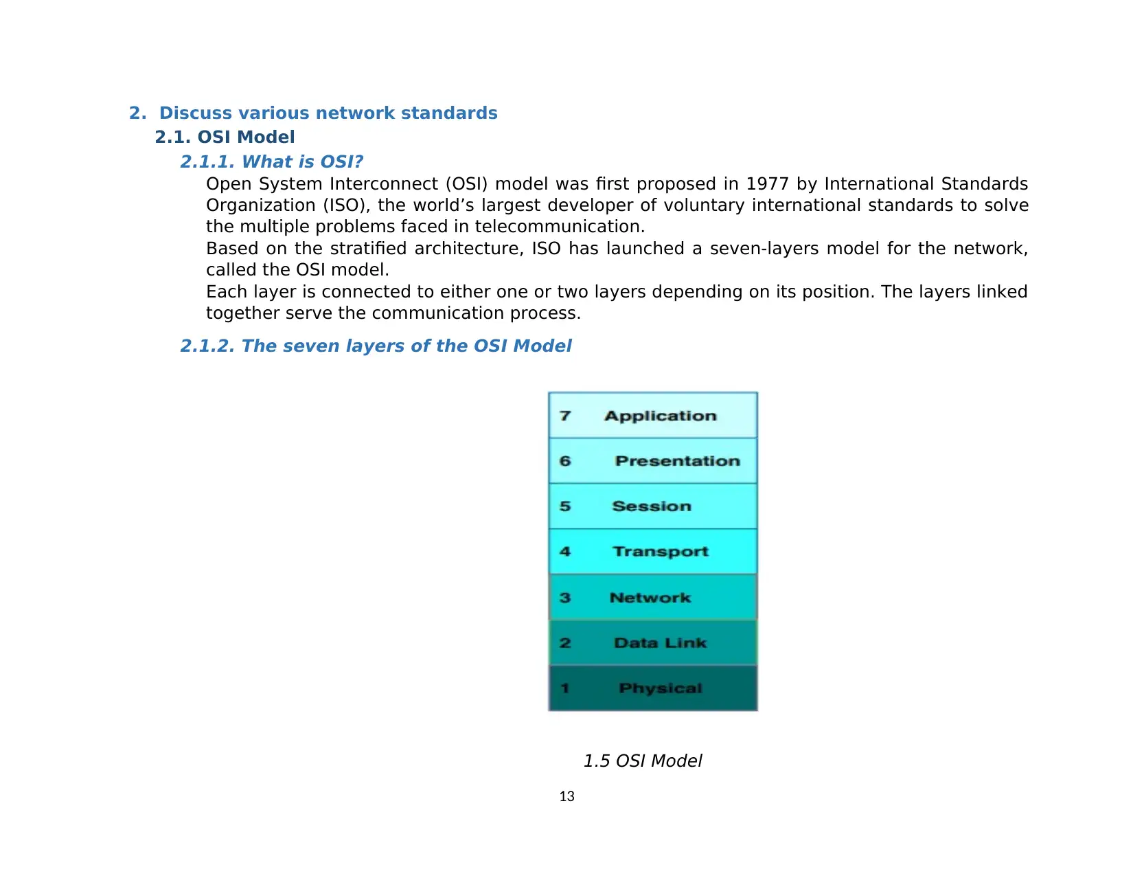
Open System Interconnect (OSI) model was first proposed in 1977 by International Standards
Organization (ISO), the world’s largest developer of voluntary international standards to solve
the multiple problems faced in telecommunication.
Based on the stratified architecture, ISO has launched a seven-layers model for the network,
called the OSI model.
Each layer is connected to either one or two layers depending on its position. The layers linked
together serve the communication process.
2.1.2. The seven layers of the OSI Model
1.5 OSI Model
13
Paraphrase This Document
Need a fresh take? Get an instant paraphrase of this document with our AI Paraphraser
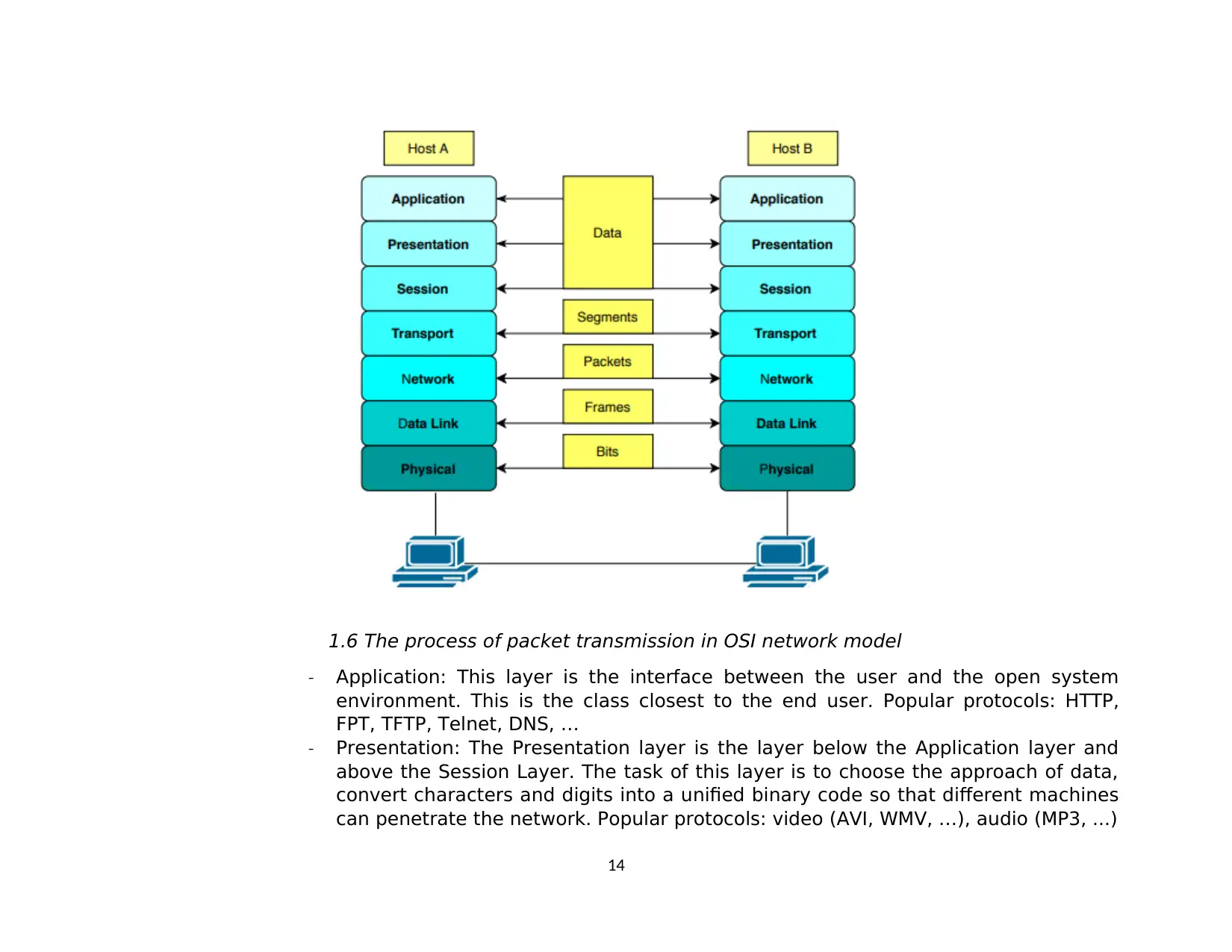
1.6 The process of packet transmission in OSI network model
- Application: This layer is the interface between the user and the open system
environment. This is the class closest to the end user. Popular protocols: HTTP,
FPT, TFTP, Telnet, DNS, …
- Presentation: The Presentation layer is the layer below the Application layer and
above the Session Layer. The task of this layer is to choose the approach of data,
convert characters and digits into a unified binary code so that different machines
can penetrate the network. Popular protocols: video (AVI, WMV, …), audio (MP3, ...)
14
- Session: Establish, maintain, synchronize and cancel communication sessions. The
Session is below the Presentation layer.
- Transport: The Transport layer is below the Session layer are received. This layer
helps to ensure the reliability of data transfer and data integrity from the sender to
the receiver.
Popular protocols:
Transmission Control Protocol (TCP): connection-oriented, reliable.
User Datagram Protocol (UDP): connectionless, unreliable.
- Network: The Network layer is below the Transport layer. It is responsible for
routing the packet based on its logical address.
- Data Link: The Data Link layer is below the Network layer and concerned with
physical addressing. The Data Link layer provides the physical transmission of the
data.
The Data Link layer is made up of 2 sublayers:
Upper layer: Logical Link Control (LLC).
Lower layer: Media Access Control (MAC).
- Physical: Transmission of an unstructured bit stream over a physical link between
end systems
2.1.3. Advantages
- Separation of online information activities into smaller and simpler parts.
- It standardizes network components to allow the development of a network from a
product vendor.
- Allow different types of hardware and software to communicate.
- Allow the person who designs the subject and develops the function in a modular
fashion.
- It makes network learning easier.
2.1.4. Disadvantages
- The OSI model is very complex.
15
- It is purely a theoretical model that does not consider the availability of
appropriate technology. This limits its practical implementation.
- After being launched, the OSI model didn’t meet the actual needs as well as the
TCP / IP model.
- There are duplicates of services in different classes. Services such as addressing,
flow control and error are provided by multiple layers.
2.2. TCP/IP Model
2.2.1. What is TCP/IP Model?
TCP/IP model (Transmission Control Protocol/ Internet Protocol) was created in the 1970s
by DARPA (Defense Advance Research Project Agency) as an open, vendor-neutral,
public networking model for Provides general instructions for designing and
implementing network protocols.
TCP/IP model consists of 4 layer:
- Class / 4th floor: Application
- Class / 3rd floor: Transport
- Class / 2nd floor: Internet
- Class/ 1st floor: Network Access
16
Secure Best Marks with AI Grader
Need help grading? Try our AI Grader for instant feedback on your assignments.
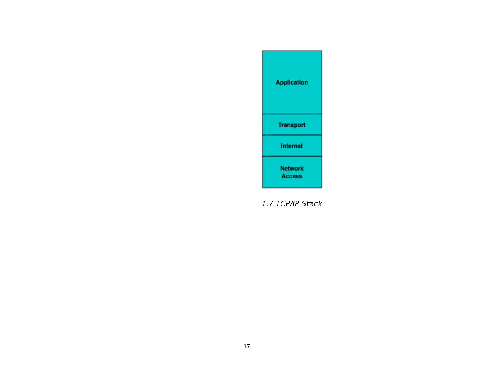
1.7 TCP/IP Stack
17
17
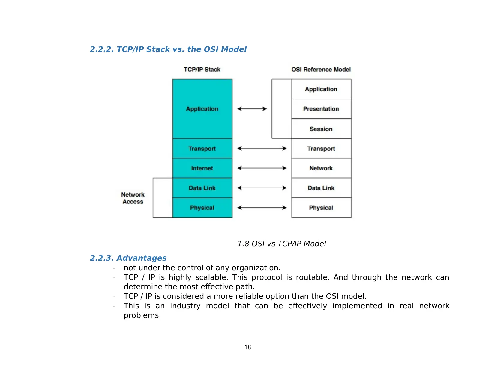
2.2.2. TCP/IP Stack vs. the OSI Model
1.8 OSI vs TCP/IP Model
2.2.3. Advantages
- not under the control of any organization.
- TCP / IP is highly scalable. This protocol is routable. And through the network can
determine the most effective path.
- TCP / IP is considered a more reliable option than the OSI model.
- This is an industry model that can be effectively implemented in real network
problems.
18
2.2.4. Disadvantages
- Assigning a centralized TCP / IP domain name requires effort and registration costs.
- It is general in nature. Therefore, it can’t represent any protocol stack other than
TCP/IP.
- It does not clearly distinguish the concepts of services, interfaces, and protocols.
Therefore, it is not suitable to describe new technologies in new networks.
II. Explain the impact of network structure, communication and bandwidth requirements
1. Impact of network structure requirements
Network topology refers to the physical layout or logic of the network.
Network topology is the arrangement of the various elements (link, nodes, etc.) of a computer
network.
Topology are divided into two types:
- Physical topology: it refers to the topology of the Local Area Network (LAN). It is the placement
of the various components of a network, including device location and cable installation
- Logical topology: illustrates how data flows within a network, regardless of its physical design.
2. Types of Topologies
There are 6 different types of physical topologies:
- BUS topology
- RING topology
- STAR topology
- MESH topology
- TREE topology
- HYBRID topology
3. STAR topology
Star-shaped networks include a center and information nodes.
All nodes connected to a central Hub with separated cables. Data passes through hub before
reaching destination.
19
Paraphrase This Document
Need a fresh take? Get an instant paraphrase of this document with our AI Paraphraser
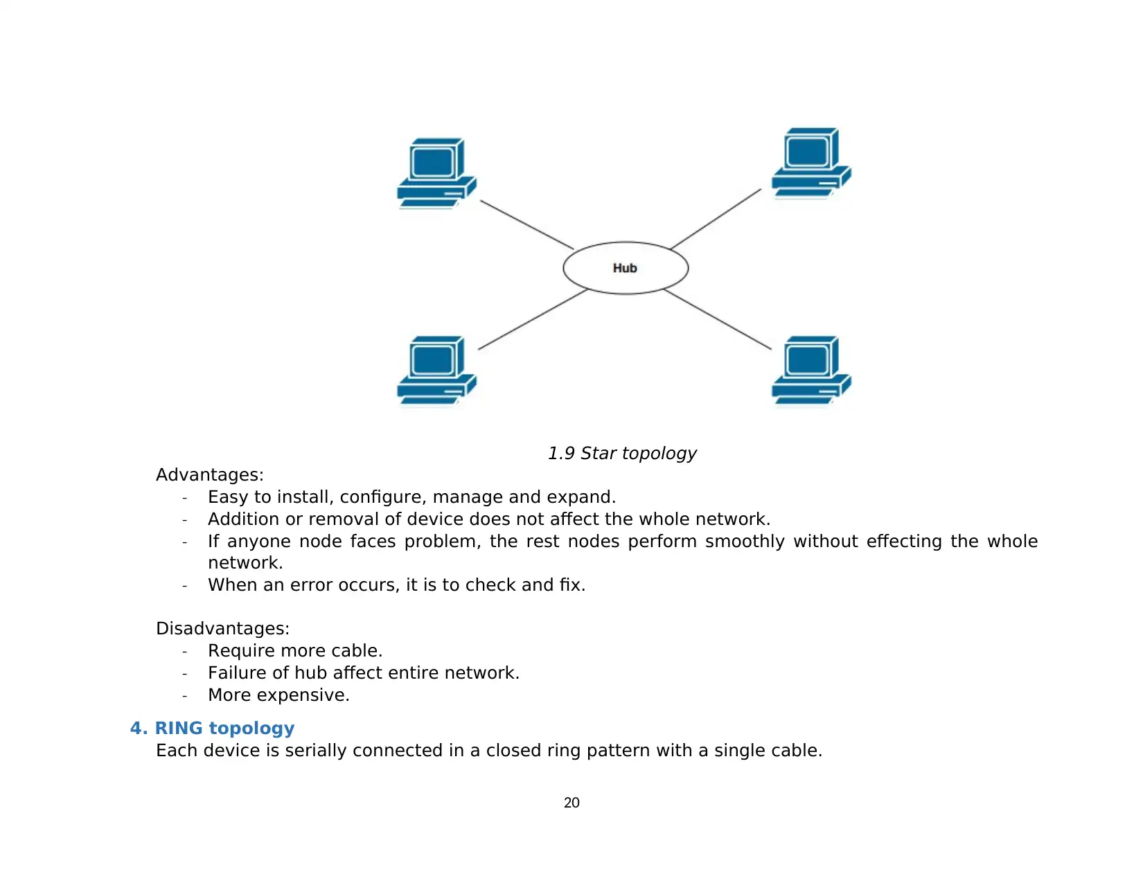
1.9 Star topology
Advantages:
- Easy to install, configure, manage and expand.
- Addition or removal of device does not affect the whole network.
- If anyone node faces problem, the rest nodes perform smoothly without effecting the whole
network.
- When an error occurs, it is to check and fix.
Disadvantages:
- Require more cable.
- Failure of hub affect entire network.
- More expensive.
4. RING topology
Each device is serially connected in a closed ring pattern with a single cable.
20
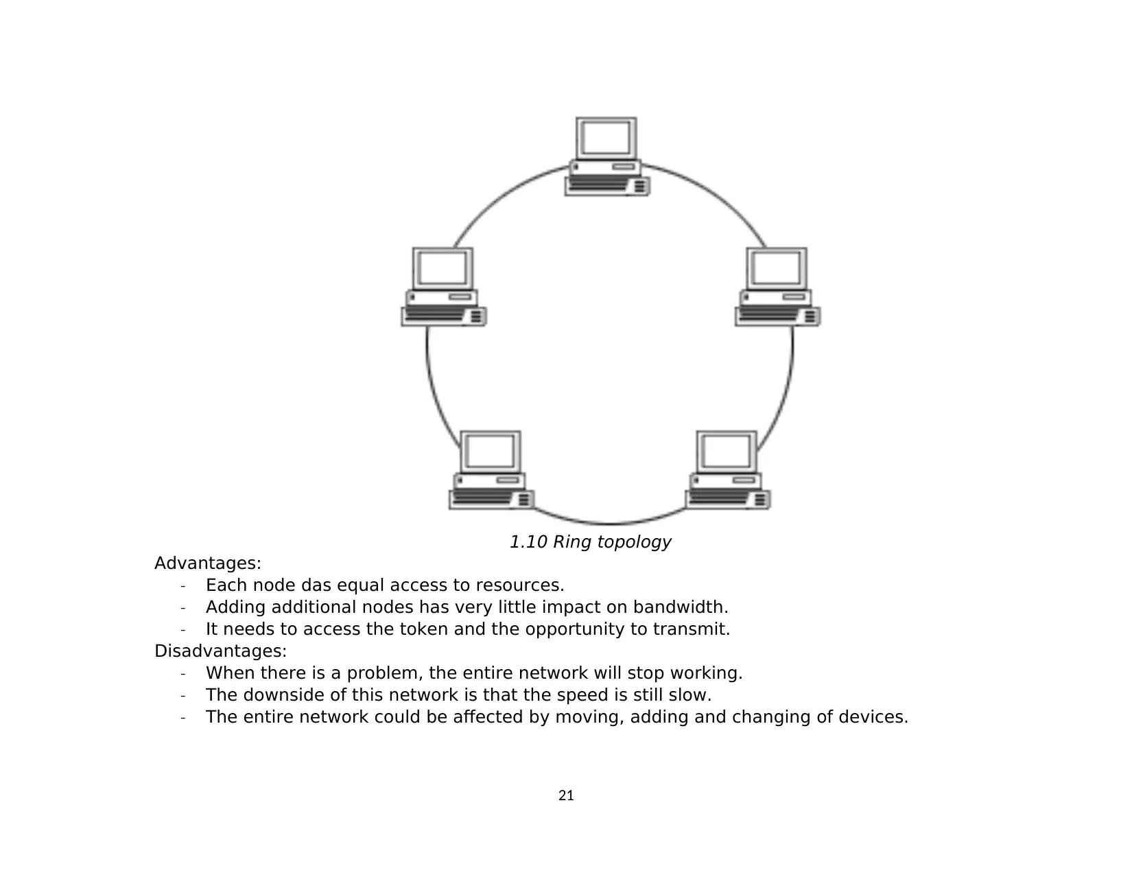
1.10 Ring topology
Advantages:
- Each node das equal access to resources.
- Adding additional nodes has very little impact on bandwidth.
- It needs to access the token and the opportunity to transmit.
Disadvantages:
- When there is a problem, the entire network will stop working.
- The downside of this network is that the speed is still slow.
- The entire network could be affected by moving, adding and changing of devices.
21
5. BUS topology
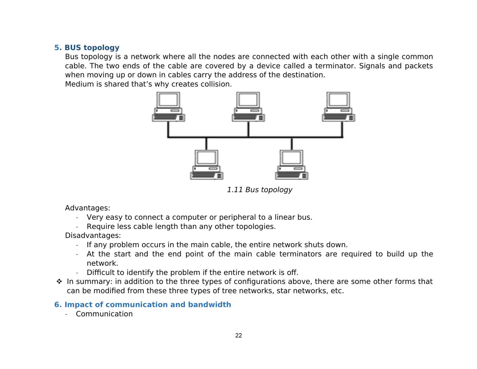
Bus topology is a network where all the nodes are connected with each other with a single common
cable. The two ends of the cable are covered by a device called a terminator. Signals and packets
when moving up or down in cables carry the address of the destination.
Medium is shared that’s why creates collision.
1.11 Bus topology
Advantages:
- Very easy to connect a computer or peripheral to a linear bus.
- Require less cable length than any other topologies.
Disadvantages:
- If any problem occurs in the main cable, the entire network shuts down.
- At the start and the end point of the main cable terminators are required to build up the
network.
- Difficult to identify the problem if the entire network is off.
In summary: in addition to the three types of configurations above, there are some other forms that
can be modified from these three types of tree networks, star networks, etc.
6. Impact of communication and bandwidth
- Communication
22
Secure Best Marks with AI Grader
Need help grading? Try our AI Grader for instant feedback on your assignments.
Data communication is the process of transmitting data between two or more computers or
transmitting data from one place to another and vice versa based on the communication between
nodes that can transmit to communicate with each other, such as copper wire or wireless signal.
- The concept of bandwidth is closely linked to the ability of a system to transmit information. In
order to transmit data, the signal must change in a certain way and the rate at which these
changes occur affects the speed of information transmission.
The term hard bandwidth is used to describe not only data transfer speed but also data
processing speed. This is essentially a flux concept applied to a processing system rather than a
communication system.
7. Compare common network principles
Bus topology Ring topology Star topology
Application Good for small
networks and
networks with
low traffic and
low data traffic
Good for cases where the
network has a few
stations operating at high
speed, not far apart or the
network has unevenly
distributed data
Currently the star network
is the best way for the case
of data and signal
integration. Public networks
have this structure
Complexity Not complicated Requiring relatively
complex installation
The complexity depends on
the central device, which is
generally easy
Efficiency Very good under
low load can
reduce
performance
very quickly
Effective in the case of
high traffic volume and is
quite stable
Good for medium load
Defect A broken station
does not affect
the whole
network
A faulty station can affect
the whole system. Difficult
to find broken network
button.
Only hub is failure point.
The reliability of the system
depends on the central
device, the network only
fails when the central
23
device fails
Cost Relatively low The cost of ring topology
is low
The cost of star topology is
high
Ability of
extension
Adding and
reshaping is easy
Whereas to add a new
node in ring topology, the
connection must be
broken.
A new cable is added to the
central hub to add a new
node.
8. How protocols allow the efficiency of networked systems
TCP
Transmission Control Protocol (TCP) is an example of connection-oriented protocol.
TCP is reliable protocol. That is, the receiver always sends positive or negative
acknowledgement of the packet to the sender, so that the sender always has clear clues
as to whether the packet has reached its destination or not.
TCP ensures that data arrive at the intended destination in the order it is sent.
TCP communication operates in Server / Client point-to-point model. Three –way
handshake is used for connection management.
Application that use TCP to send their data information is DNS, FTP, HTTP, SMTP, …
UDP
User Datagram Protocol (UDP) is an example of connectionless protocol.
When an application uses UDP, packets are only sent to the recipient. The sender does
not wait to make sure the recipient receives the packet or not, but it continues to send
subsequent packets. If the recipient misses a few UDP packets, the packet is lost
because the sender will not resend them. This means devices can communicate faster.
UDP is used when speed is desired and error correction is not required. For example,
UDP is often used for live broadcasts and online games.
TCP is more secure than UDP. In many organizations, firewalls and routers prohibit UDP
packets, this is because hackers often use UDP ports.
Application that use UDP to send their data information is DNS, TFTP …
24
III. Explain networking devices and operations
1. Network devices and server types
1.1. Networking devices
To connect the Internet from home to home and office electronics. Indispensable network
devices such as Repeater, Switch, Router, Bridge or Hub. These devices have the same
function of connecting and transmitting internet signals, but they have different characteristics.
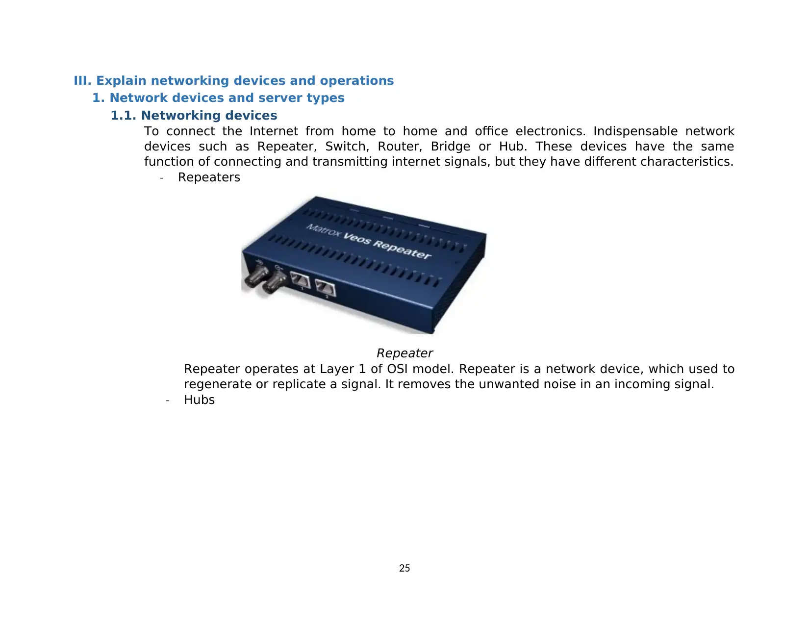
- Repeaters
Repeater
Repeater operates at Layer 1 of OSI model. Repeater is a network device, which used to
regenerate or replicate a signal. It removes the unwanted noise in an incoming signal.
- Hubs
25
Paraphrase This Document
Need a fresh take? Get an instant paraphrase of this document with our AI Paraphraser
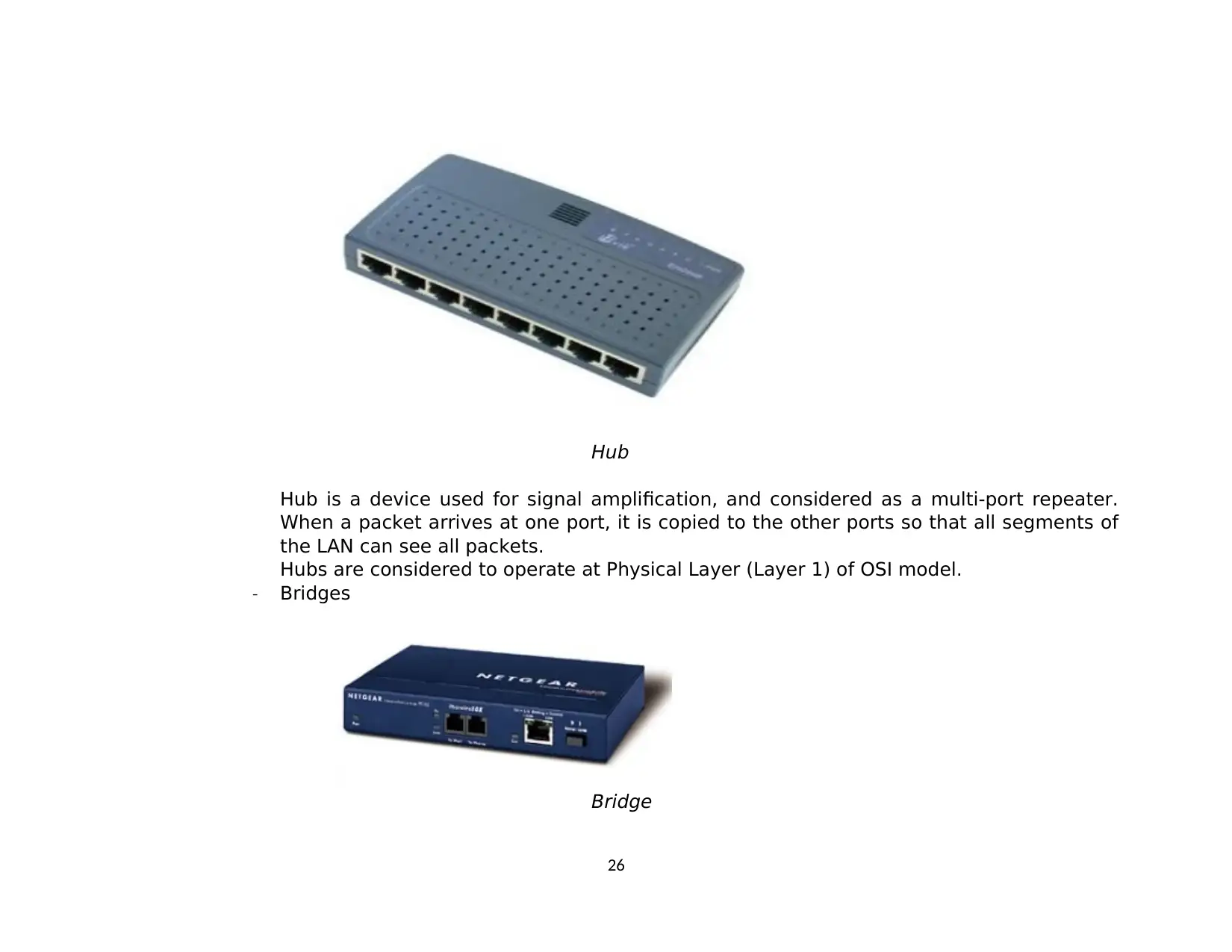
Hub
Hub is a device used for signal amplification, and considered as a multi-port repeater.
When a packet arrives at one port, it is copied to the other ports so that all segments of
the LAN can see all packets.
Hubs are considered to operate at Physical Layer (Layer 1) of OSI model.
- Bridges
Bridge
26
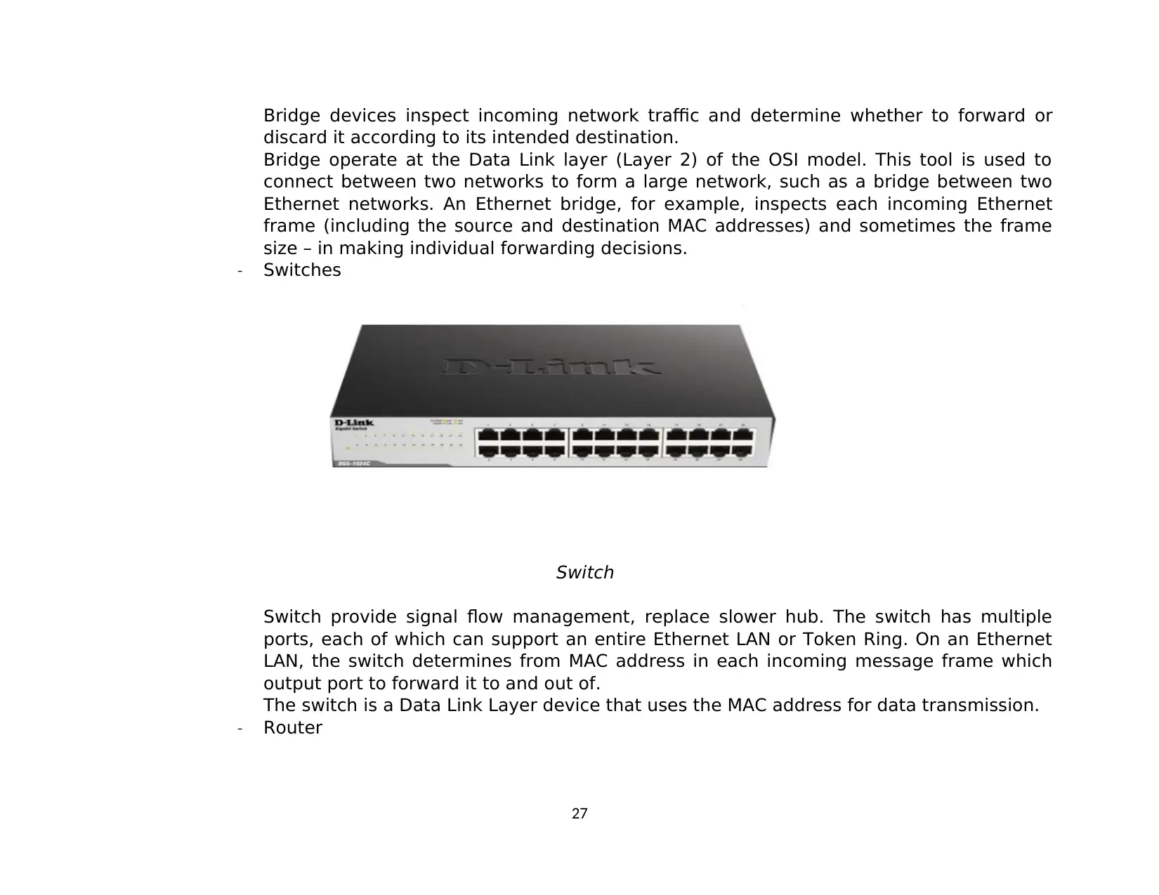
Bridge devices inspect incoming network traffic and determine whether to forward or
discard it according to its intended destination.
Bridge operate at the Data Link layer (Layer 2) of the OSI model. This tool is used to
connect between two networks to form a large network, such as a bridge between two
Ethernet networks. An Ethernet bridge, for example, inspects each incoming Ethernet
frame (including the source and destination MAC addresses) and sometimes the frame
size – in making individual forwarding decisions.
- Switches
Switch
Switch provide signal flow management, replace slower hub. The switch has multiple
ports, each of which can support an entire Ethernet LAN or Token Ring. On an Ethernet
LAN, the switch determines from MAC address in each incoming message frame which
output port to forward it to and out of.
The switch is a Data Link Layer device that uses the MAC address for data transmission.
- Router
27
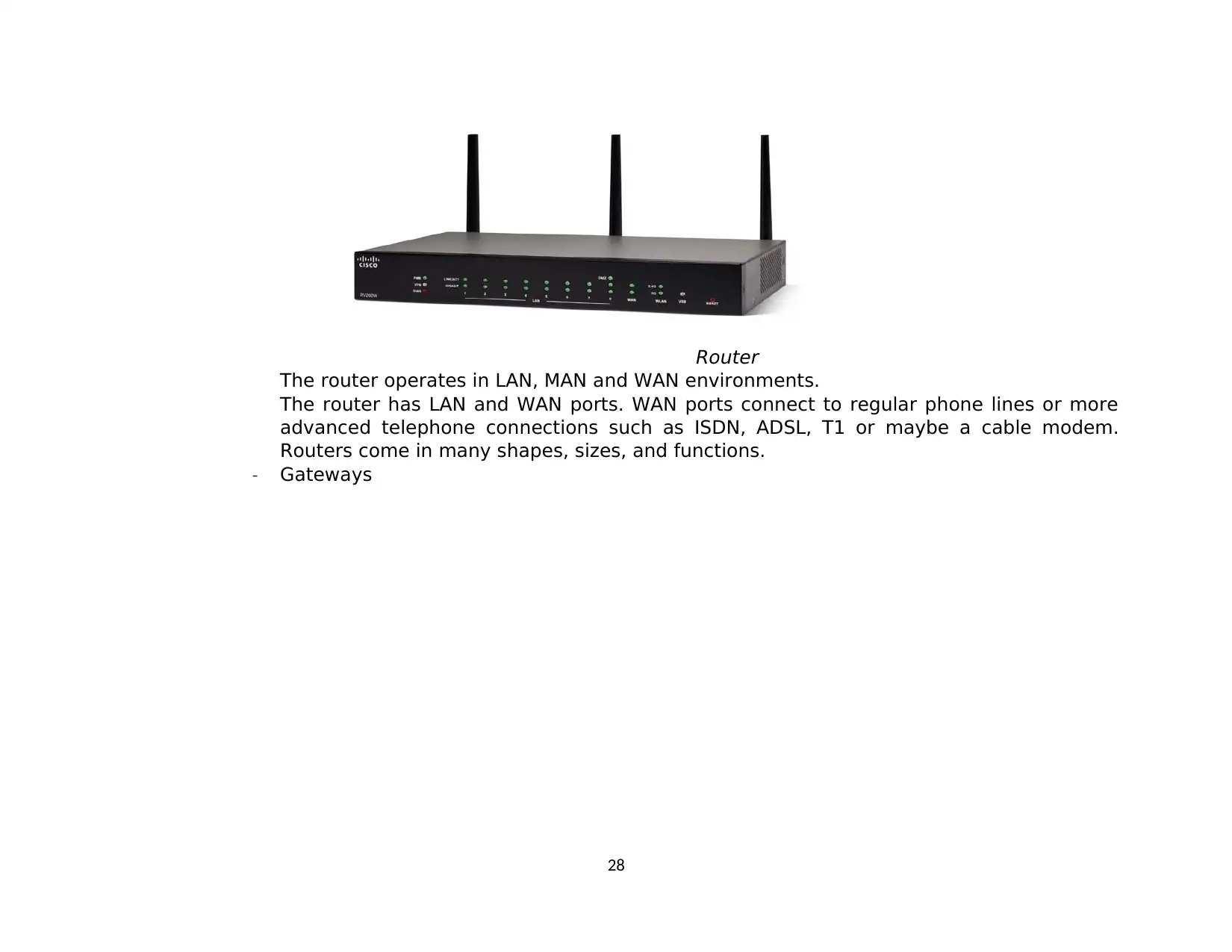
Router
The router operates in LAN, MAN and WAN environments.
The router has LAN and WAN ports. WAN ports connect to regular phone lines or more
advanced telephone connections such as ISDN, ADSL, T1 or maybe a cable modem.
Routers come in many shapes, sizes, and functions.
- Gateways
28
The router operates in LAN, MAN and WAN environments.
The router has LAN and WAN ports. WAN ports connect to regular phone lines or more
advanced telephone connections such as ISDN, ADSL, T1 or maybe a cable modem.
Routers come in many shapes, sizes, and functions.
- Gateways
28
Secure Best Marks with AI Grader
Need help grading? Try our AI Grader for instant feedback on your assignments.
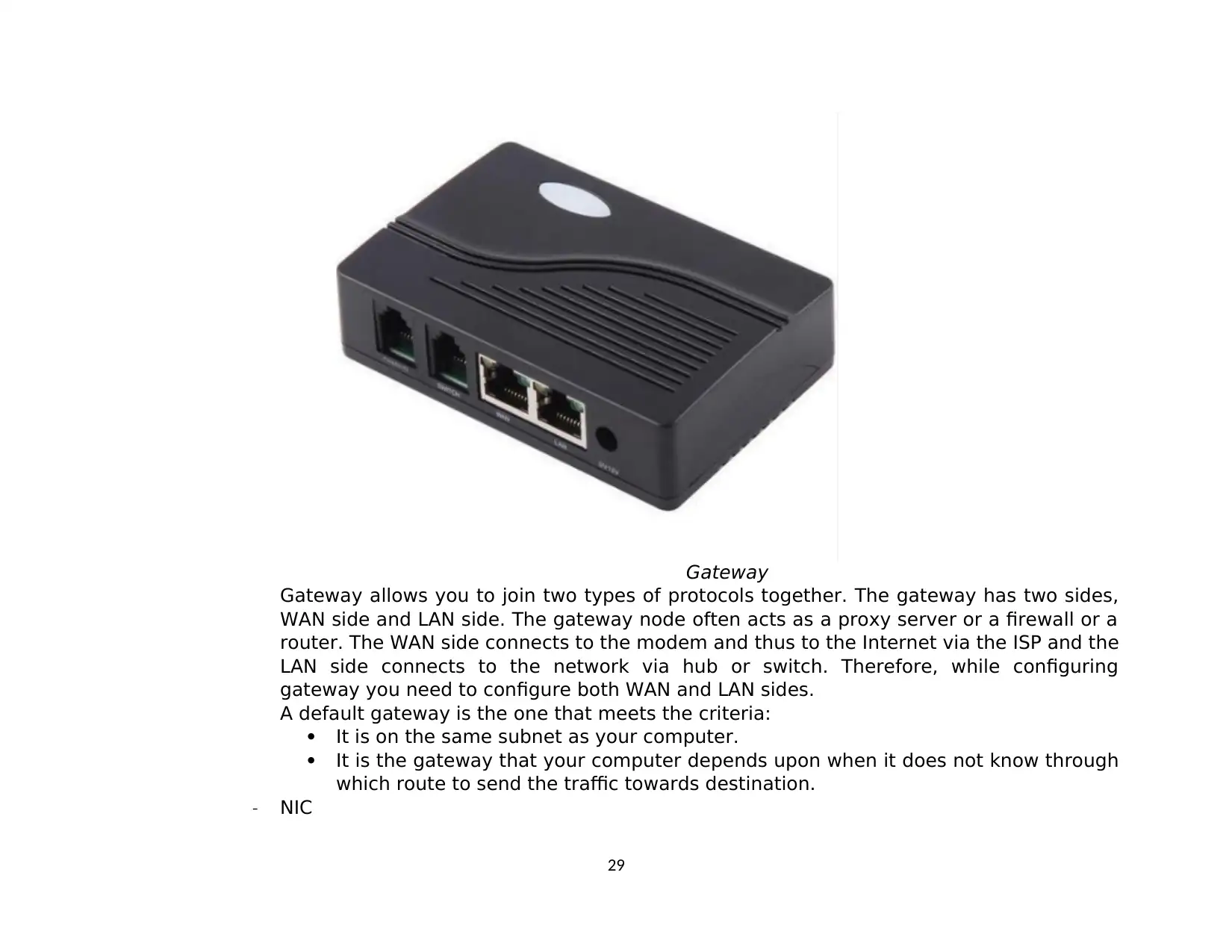
Gateway
Gateway allows you to join two types of protocols together. The gateway has two sides,
WAN side and LAN side. The gateway node often acts as a proxy server or a firewall or a
router. The WAN side connects to the modem and thus to the Internet via the ISP and the
LAN side connects to the network via hub or switch. Therefore, while configuring
gateway you need to configure both WAN and LAN sides.
A default gateway is the one that meets the criteria:
It is on the same subnet as your computer.
It is the gateway that your computer depends upon when it does not know through
which route to send the traffic towards destination.
- NIC
29
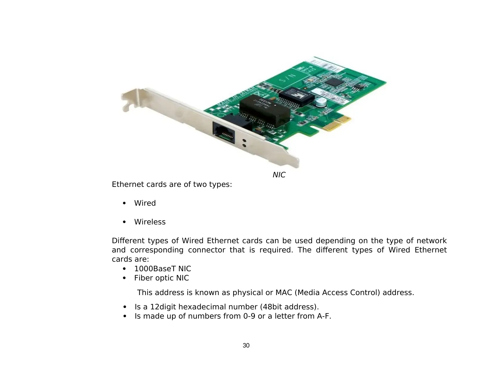
NIC
Ethernet cards are of two types:
Wired
Wireless
Different types of Wired Ethernet cards can be used depending on the type of network
and corresponding connector that is required. The different types of Wired Ethernet
cards are:
1000BaseT NIC
Fiber optic NIC
This address is known as physical or MAC (Media Access Control) address.
Is a 12digit hexadecimal number (48bit address).
Is made up of numbers from 0-9 or a letter from A-F.
30
It is provided by a device known as Network Interface Card (NIC) and it operates at
layer 2 of the OSI model.
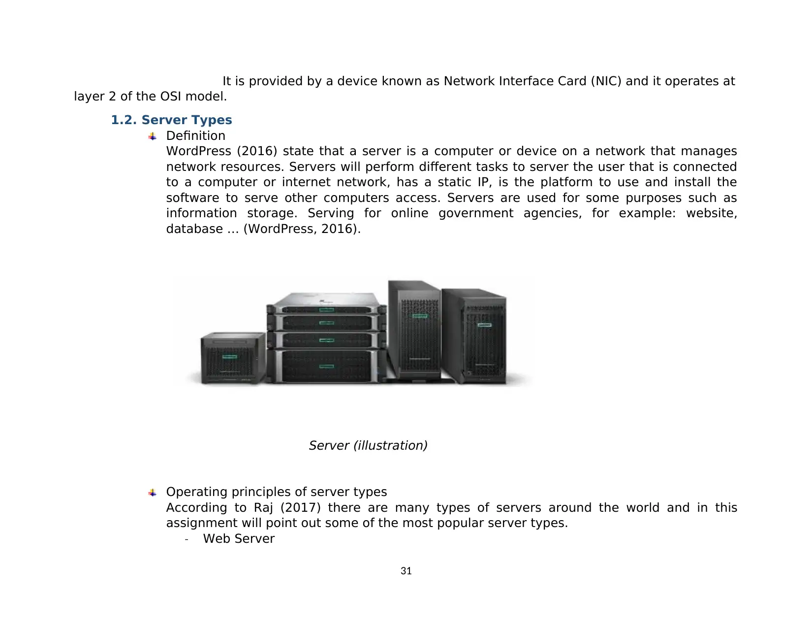
1.2. Server Types
Definition
WordPress (2016) state that a server is a computer or device on a network that manages
network resources. Servers will perform different tasks to server the user that is connected
to a computer or internet network, has a static IP, is the platform to use and install the
software to serve other computers access. Servers are used for some purposes such as
information storage. Serving for online government agencies, for example: website,
database … (WordPress, 2016).
Server (illustration)
Operating principles of server types
According to Raj (2017) there are many types of servers around the world and in this
assignment will point out some of the most popular server types.
- Web Server
31
Paraphrase This Document
Need a fresh take? Get an instant paraphrase of this document with our AI Paraphraser
Web Server is an end device or software dedicated to processing client request and
provide World Wide Web servers. In other words, web server is a repository to store
all the data provided on the internet that it is assigned to manage. When a browser
needs a files stored on a web server, the browser sends the request to the web server
via HTTP protocol. When the request reaches the correct web server, the web server
sends the requested document back, also via HTTTP protocol.
- Application Server
Application server is a type of server created to store, operate, install and provide
services to users. In many times, the application server works with the web server
and it is called the web application server.
- Printer Server
The print server is a server that connects the printer to a client via the internet. The
print server is used to print jobs from the computer and send the print job to the
appropriate printers.
- Proxy Server
It is a server standing between an application, like a web browser and a real server. It
acts as a mediator between the client program and the external server for filtering
requests to improve performance and share connections.
- Database Server
Database server is the dedicated server used to store websites, data and information.
A database server is a basic application on the server / workstation architecture
model.
- FTP Server
FTP server (File Transfer Protocol) is a type of server for changing of data using TCP/IP
protocol. The FTP server, running software
that provides FTP services, is called a server, listening to the service requests of other
computers on the network. An FTP service is a software application that runs file
transfer protocols, which
exchange files over the internet.
- Mail Server
32
Mail server is the system used to send e-mail, messages over the internet or over
internet. It is a tool for people to exchange information. These types of server receive
to e-mail of message and send to client.
- DNS Server
DNS (Domain Name System) is the system used to translate domain names placed so
that it is easy to remember people such as fpt.edu.vn to the corresponding digital
internet (IP-Internet Protocol) address. As well as identifying and locating the
computer system and resources on the internet instead of using the IP address to
access, it will be difficult to remember for user.
- DHCP Server
DHCP server (Dynamic Host Configuration Protocol) is a type of servers used to
provide dynamic IP address for workstations. When there is request from DHCP client,
DHCP server checks in its database to find the IP address and grant this address to
DHCP client.
- Virtual Private Server – VPS
VPS is a server type separated from the above physical server by using virtualization
technology. VPS is initialized and run on a physical server. At peak times the physical
server may hang resulting in the VPS may temporarily stop working.
- Cloud Server
Cloud server is a virtual that combines many different servers in the internet. Data is
virtualized and stored through internet. This server using cloud computing technology
to operate.
2. Discuss the inter-dependence of workstation hardware with relevant networking
software.
- Network hardware – It is a computer component that allows data transmission between electronic
devices. Although it contains many hardware components, there are many different types that
make up the total functionality of the network.
- Router - It is often used to connect two or more network segments with different protocols and
architectures. This device features the best route decision making for data transmission and
packet filtering.
33
- Gateway - it works with different protocols. It resides in the network node and interfaces with
another network.
- Switch - A switch receives data from a port, uses packet switching to resolve the target device,
and then forwards the data to a specific destination, instead of transmitting it as a hub.
- Bridges - it allows a large network area into a smaller, more efficient segment. They make the
data updated and create connections on both sides. It forwards packets from source network to
destiny network.
- Modem - A modem is a device that converts electrical signals sent through telephone lines,
coaxial cables or other similar wires.
- File server - File server is a networked computer that provides space to store and share data such
as text, images, audio, and video. A server that can be reserved is such a case, its entire
processing power is allocated to the network function.
- Network operating system - it is loaded into the server's hard disk along with system
management tools and user utilities. The operating system plays an intermediary role in the
communication between users and computer hardware, providing an environment that allows
users to develop and execute their applications easily.
- Workstation - workstations or nodes are attached to the server via network interface cards and
cables. The workstation can be connected to a network or independent systems like a normal
computer. A workstation is a higher-performance computer used for a specific task, usually the
hardware and software on a workstation designed to provide the best performance in a type of
work (technical graphics 3D, video rendering, logic calculations, artificial intelligence ...).
- Network interface card - all devices connected to the LAN need a network interface card to plug
into the LAN.
- Server Software is a computer that is on the network and shares its application resources with
network users. From there, users can access and use the application.
- Network cabling - The purpose of cable installation is to ensure the speed needed for network
communication needs. There are three main types of cables used to connect most networks:
Coaxial
Twisted-Pair
Fiber-Optic
34
Secure Best Marks with AI Grader
Need help grading? Try our AI Grader for instant feedback on your assignments.
2.1. Factors to consider when choose a server
- Price
This is the aspect most of us will look at first when choosing a hosting provider. You should set
a budget right from the start and based on that budget to have an appropriate plan. The
server market is quite diverse. You have many choices; therefore, take a closer look at the
features that each host provides.
- Hardware
Once you’ve ticked off your basic requirements in terms of processing power, memory and
storage, take a look at your hardware. The server’s hardware can be distinguished by brand
and model. You need to choose a supplier known for that kind of server. This ensures you will
buy a server from a reputable, famous brand and fully supported during use.
- Features / Add-Ons
Servers are invested for long-term use, so the extent of system expansion and features should
be considered. If you see one that offers something you need or find important, that might be
a good indicator that you should consider when using that company.
- Support
For customers that go down the managed route, cost and accessibility of support are vitally
important factors to consider. So be sure to ask your provider about the setup they have. and
who 'will be available to answer the phone or receive a support ticket
- Security
When choosing dedicated server hosting, it is important that your hosting provider access
security with the severity that it deserves. Most small businesses have no IT department
available, so they often have to outsource. But if you buy a server from a reputable provider,
you will always be offered the maintenance package included.
2.2. Select server for business
- For small and medium enterprises
For a new business, cloud-based servers are an option for them but dedicated on-premises
servers can give them more security and control over critical data.
The main advantage of having your own on-premises server is that it gives you more control -
and security - over your business's software and data. Besides, for higher demands such as
35
storing large amounts of information or needing to exchange data back and forth, server use
can be considered mandatory.
- For big business
Servers for large businesses are needed because of management needs capacity and
operating speed are always the top priority.
Some of the needs that server helps solve for this business object include:
Running software: management, finance ...
Backup, data backup.
Secure data protection and confidentiality.
Local anti-attack.
Save and manage a large amount of business information, project management
information ...
Manage and operate the system remotely.
Increased processing capability, allowing for powerful processing capabilities during peak
periods, the need of resources such as RAM, CPU, high speed transmission
IV. Design efficient networked systems
1. Design a networked system to meet given specification
1.1. Request
The requirement given is: Design a networked system for a local educational institution includes:
- People: 200 students, 15 teachers, 12 marketing and administration staff, 5 higher
managers include the head of academics and the program manager, 3 computer network
administrators.
- Resources: 50 student lab computers, 35 computer staff, 3 printers.
- Building: 3 floors, all computers and printers are on the ground floor outside the IT lab - a
laboratory is located on the first floor and another is on the second floor.
1.2. Design plan
Design plan
Step by step plan of setting up:
Step 1: Design a Logic blueprint of the network.
36
Step 2: Choice and buy devices.
Step3: set up places the devices, place computers printer to their positions.
Step 4: Install devices (router, server, switch, …).
Security: because in school, expect tests there’s not many things really need to protect
so some need to Firewall devices high price are not so needed. All wifi router are set up
by enterprise, so each person are need to come to IT and register so to access to LAN
they must get in LAB or staff room. Camera can share help this.
Target:
- Everyone can access the internet.
- All network devices in the institution can communicate with each other; Exchange
data quickly and safely.
- All network devices can access Mail and Server.
- Only administrators can access computers DHCP server.
- Only staff and manager computers can use printer.
- Only administrators can access router and switch using Telnet command.
- Do not give guest access to Database server by web (http and https).
Maintenance schedule support the network system
To support network system, administrators have to follow a maintenance schedule to
check and find errors as soon as possible.
The schedule is:
- Network administrators have to check the connections in the network every day. If
some of the connections fail, they must find out where the errors are (cable,
router, switch or end device) so they can replace or maintenance.
- Network have to check the configuration of connection of connection devices
(switch, router, …) and servers to make sure that these devices work normally.
Logical model
Network configuration for this 3 floor building includes these symbolic network devices
are: Router, Switch, PC, Printer, Wireless, server, switch layer 3.
37
Paraphrase This Document
Need a fresh take? Get an instant paraphrase of this document with our AI Paraphraser
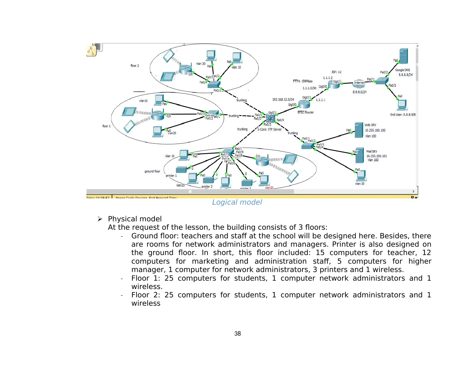
Logical model
Physical model
At the request of the lesson, the building consists of 3 floors:
- Ground floor: teachers and staff at the school will be designed here. Besides, there
are rooms for network administrators and managers. Printer is also designed on
the ground floor. In short, this floor included: 15 computers for teacher, 12
computers for marketing and administration staff, 5 computers for higher
manager, 1 computer for network administrators, 3 printers and 1 wireless.
- Floor 1: 25 computers for students, 1 computer network administrators and 1
wireless.
- Floor 2: 25 computers for students, 1 computer network administrators and 1
wireless
38
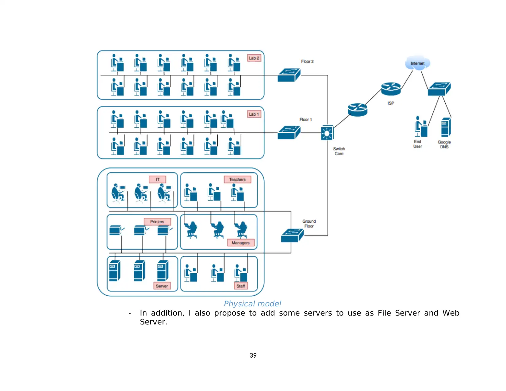
Physical model
- In addition, I also propose to add some servers to use as File Server and Web
Server.
39
- In addition, I also propose to add some servers to use as File Server and Web
Server.
39
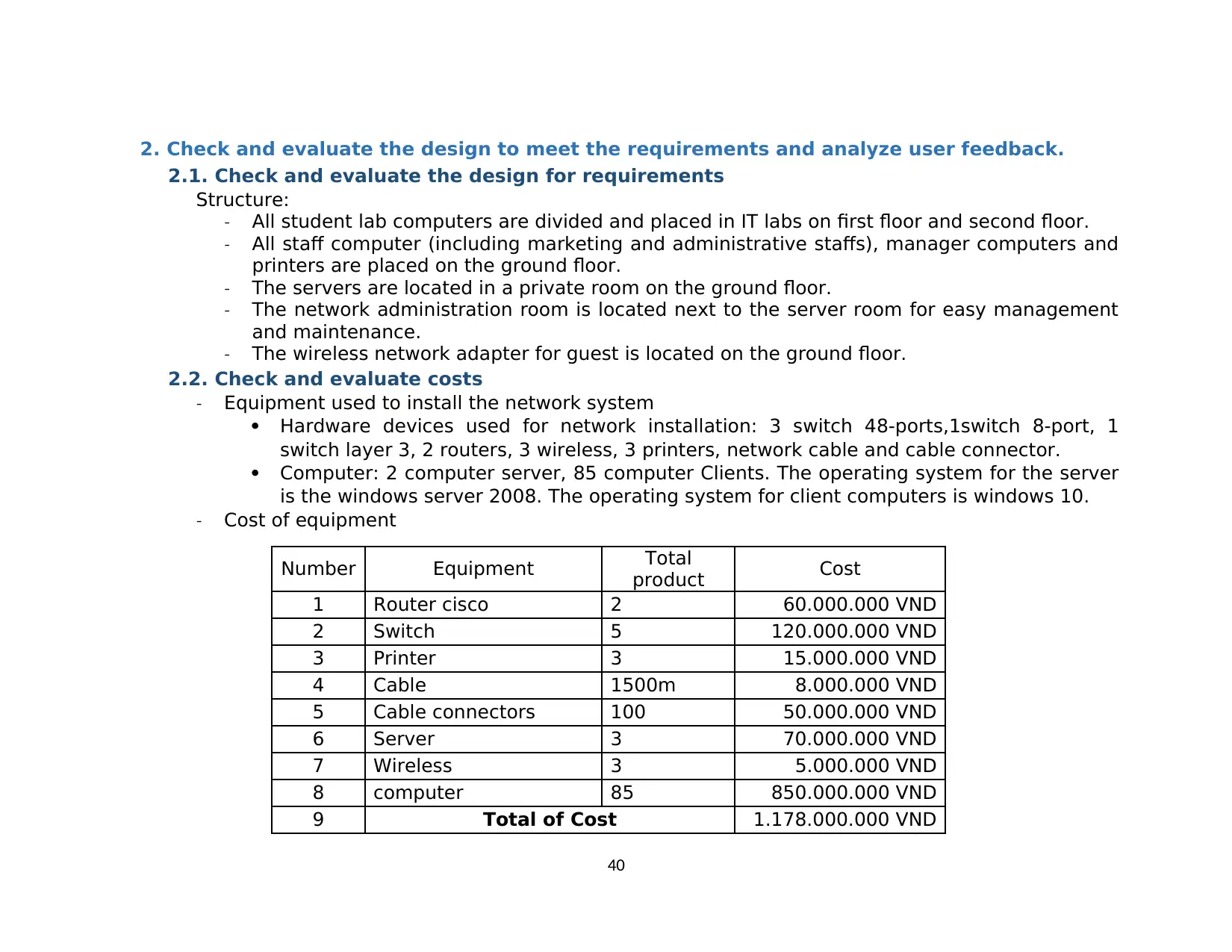
2. Check and evaluate the design to meet the requirements and analyze user feedback.
2.1. Check and evaluate the design for requirements
Structure:
- All student lab computers are divided and placed in IT labs on first floor and second floor.
- All staff computer (including marketing and administrative staffs), manager computers and
printers are placed on the ground floor.
- The servers are located in a private room on the ground floor.
- The network administration room is located next to the server room for easy management
and maintenance.
- The wireless network adapter for guest is located on the ground floor.
2.2. Check and evaluate costs
- Equipment used to install the network system
Hardware devices used for network installation: 3 switch 48-ports,1switch 8-port, 1
switch layer 3, 2 routers, 3 wireless, 3 printers, network cable and cable connector.
Computer: 2 computer server, 85 computer Clients. The operating system for the server
is the windows server 2008. The operating system for client computers is windows 10.
- Cost of equipment
Number Equipment Total
product Cost
1 Router cisco 2 60.000.000 VND
2 Switch 5 120.000.000 VND
3 Printer 3 15.000.000 VND
4 Cable 1500m 8.000.000 VND
5 Cable connectors 100 50.000.000 VND
6 Server 3 70.000.000 VND
7 Wireless 3 5.000.000 VND
8 computer 85 850.000.000 VND
9 Total of Cost 1.178.000.000 VND
40
Secure Best Marks with AI Grader
Need help grading? Try our AI Grader for instant feedback on your assignments.
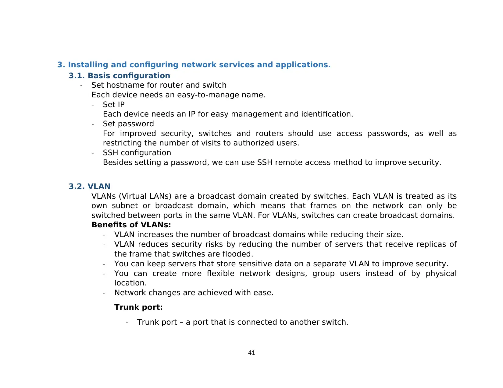
3. Installing and configuring network services and applications.
3.1. Basis configuration
- Set hostname for router and switch
Each device needs an easy-to-manage name.
- Set IP
Each device needs an IP for easy management and identification.
- Set password
For improved security, switches and routers should use access passwords, as well as
restricting the number of visits to authorized users.
- SSH configuration
Besides setting a password, we can use SSH remote access method to improve security.
3.2. VLAN
VLANs (Virtual LANs) are a broadcast domain created by switches. Each VLAN is treated as its
own subnet or broadcast domain, which means that frames on the network can only be
switched between ports in the same VLAN. For VLANs, switches can create broadcast domains.
Benefits of VLANs:
- VLAN increases the number of broadcast domains while reducing their size.
- VLAN reduces security risks by reducing the number of servers that receive replicas of
the frame that switches are flooded.
- You can keep servers that store sensitive data on a separate VLAN to improve security.
- You can create more flexible network designs, group users instead of by physical
location.
- Network changes are achieved with ease.
Trunk port:
- Trunk port – a port that is connected to another switch.
41
- To enable VLAN communication between switches, you need to configure the
switches to use VLAN trunk on the links between them. The protocol used may be
Cisco's proprietary ISL protocol or IEEE 802.1q standard. If your switches support
both ISL and 802.1q frame tagging protocols, you also need to use the switchport
trunk encapsulation [dot1q | isl] command to determine the trunk type.
3.3. DHCP
DHCP (Dynamic Host Configuration Protocol) is a protocol for allocating IP address for devices
on a network.
DHCP uses a client-server architecture; a DHCP client is configured to request network
parameters from the DHCP server. There are three components within the DHCP architecture,
including DHCP clients, DHCP servers, and DHCP relay agents.
DHCP server is a device that allocates an IP address.
3.4. Static routing
Static routes are one way we can communicate with remote networks. For static routing, the
route information is assigned by the network administrator to the router. Then, the
administration has the function of updating and deleting information about the path for the
router.
For large networks, the maintenance of the routing network for the router like this takes a lot
of time. Also for small networks, there is little change. This work is less costly. In addition, in
large networks, Static routing is often used in conjunction with dynamic routing protocols for
some special purposes.
3.5. NAT
NAT (Network Address Translation) is a technique that allows conversion from one IP address
to another. Usually NAT usually changes the address is usually the private address (Private IP)
of a network connection to a public address (IP Public).
NAT can also be considered a basis firewall. NAT maintains a table of information about each
packet sent.
Static NAT is used to permanently convert one IP address to another.
42
Static NAT is useful in cases where devices need to have a fixed address to be accessible from
outside the Internet. These devices are popular as Web servers, Mail, ...
3.6. ACL
ACLs (Access control lists) are also known as access list, which are a list of commands used to
manage access (in and out) on the device with the corresponding actions allowed (allow) or
banned (deny).
Purpose of using ACL:
- Permit or deny packets moving through the router.
- Permit or deny vty access to or from the router.
- Without ACLs, all packets could be transmitted to all parts of your network.
Types of ACLs:
- Standard ACL:
Checks source address.
Generally, allow or deny the entire protocol.
- Extended ACL:
Checks source and destination address
Generally, permits or denies specific protocols and applications.
Two methods used to identify stander and extended ACLs:
- Numbered ACLs use a number for identification.
- Named ACLs use a descriptive name or number for identification.
V. Implement and diagnose networked systems
1. Implement a network based on a prepared design
1.1. Basic configuration
I use Cisco Packet Tracer Instructor to implement the design above and follow these steps to complete the network model:
43
Paraphrase This Document
Need a fresh take? Get an instant paraphrase of this document with our AI Paraphraser
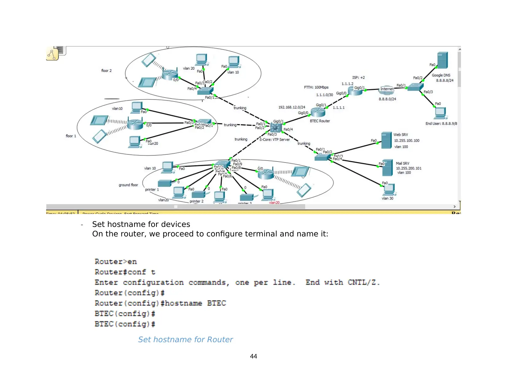
- Set hostname for devices
On the router, we proceed to configure terminal and name it:
Set hostname for Router
44
On the router, we proceed to configure terminal and name it:
Set hostname for Router
44
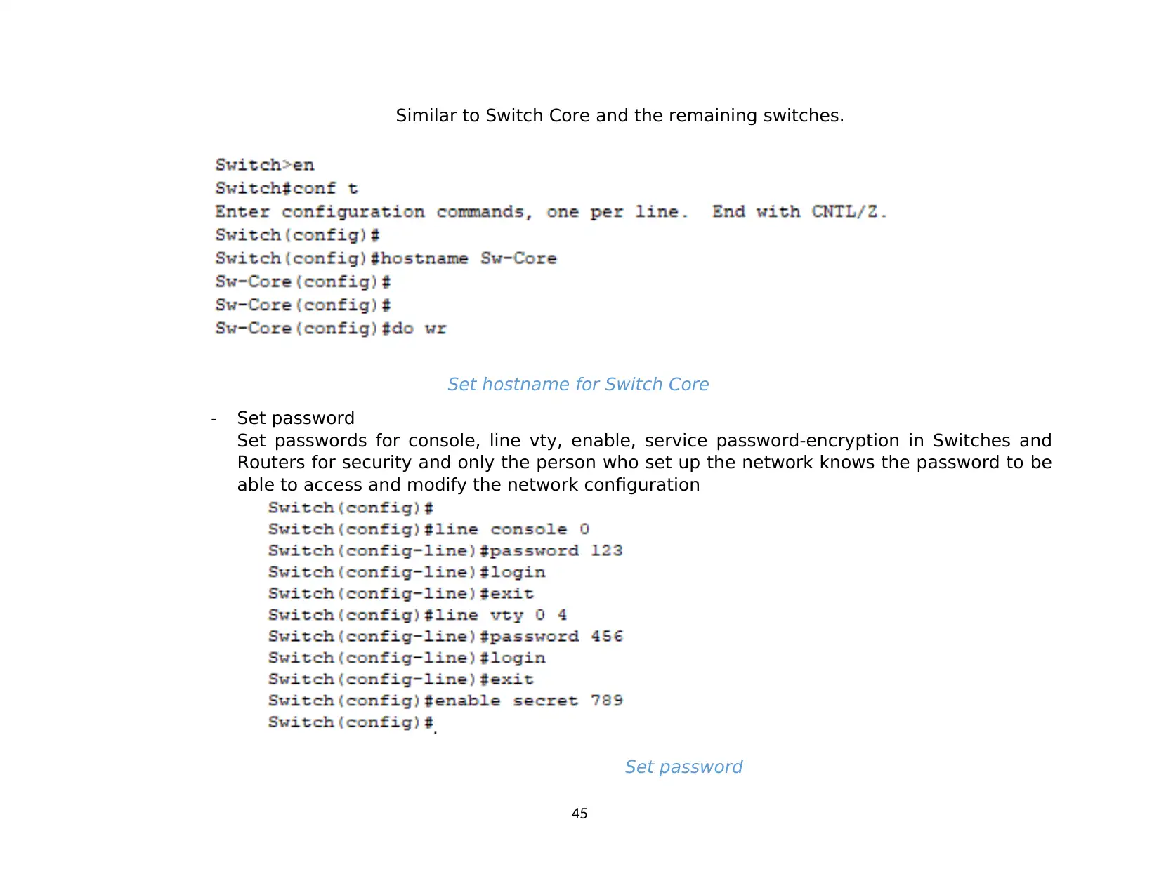
Similar to Switch Core and the remaining switches.
Set hostname for Switch Core
- Set password
Set passwords for console, line vty, enable, service password-encryption in Switches and
Routers for security and only the person who set up the network knows the password to be
able to access and modify the network configuration
Set password
45
Set hostname for Switch Core
- Set password
Set passwords for console, line vty, enable, service password-encryption in Switches and
Routers for security and only the person who set up the network knows the password to be
able to access and modify the network configuration
Set password
45
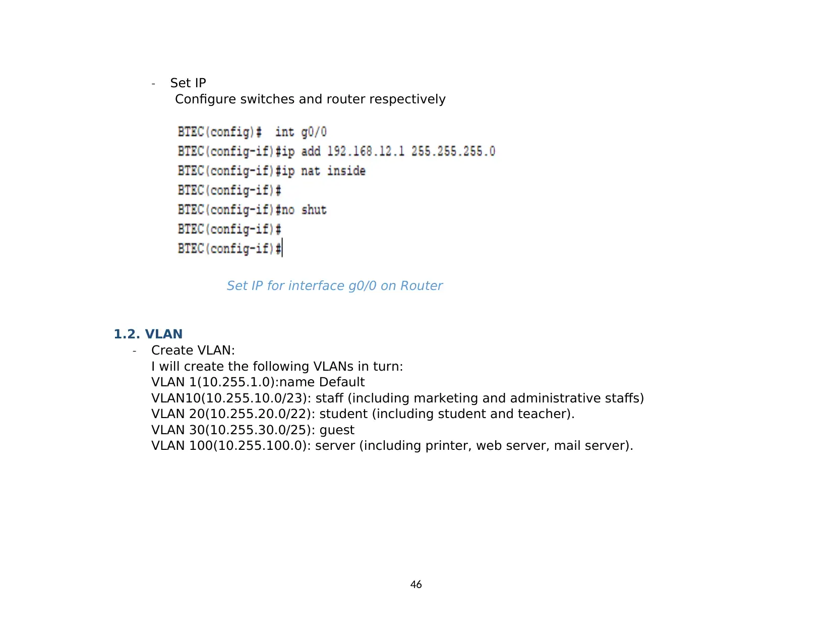
- Set IP
Configure switches and router respectively
Set IP for interface g0/0 on Router
1.2. VLAN
- Create VLAN:
I will create the following VLANs in turn:
VLAN 1(10.255.1.0):name Default
VLAN10(10.255.10.0/23): staff (including marketing and administrative staffs)
VLAN 20(10.255.20.0/22): student (including student and teacher).
VLAN 30(10.255.30.0/25): guest
VLAN 100(10.255.100.0): server (including printer, web server, mail server).
46
Secure Best Marks with AI Grader
Need help grading? Try our AI Grader for instant feedback on your assignments.
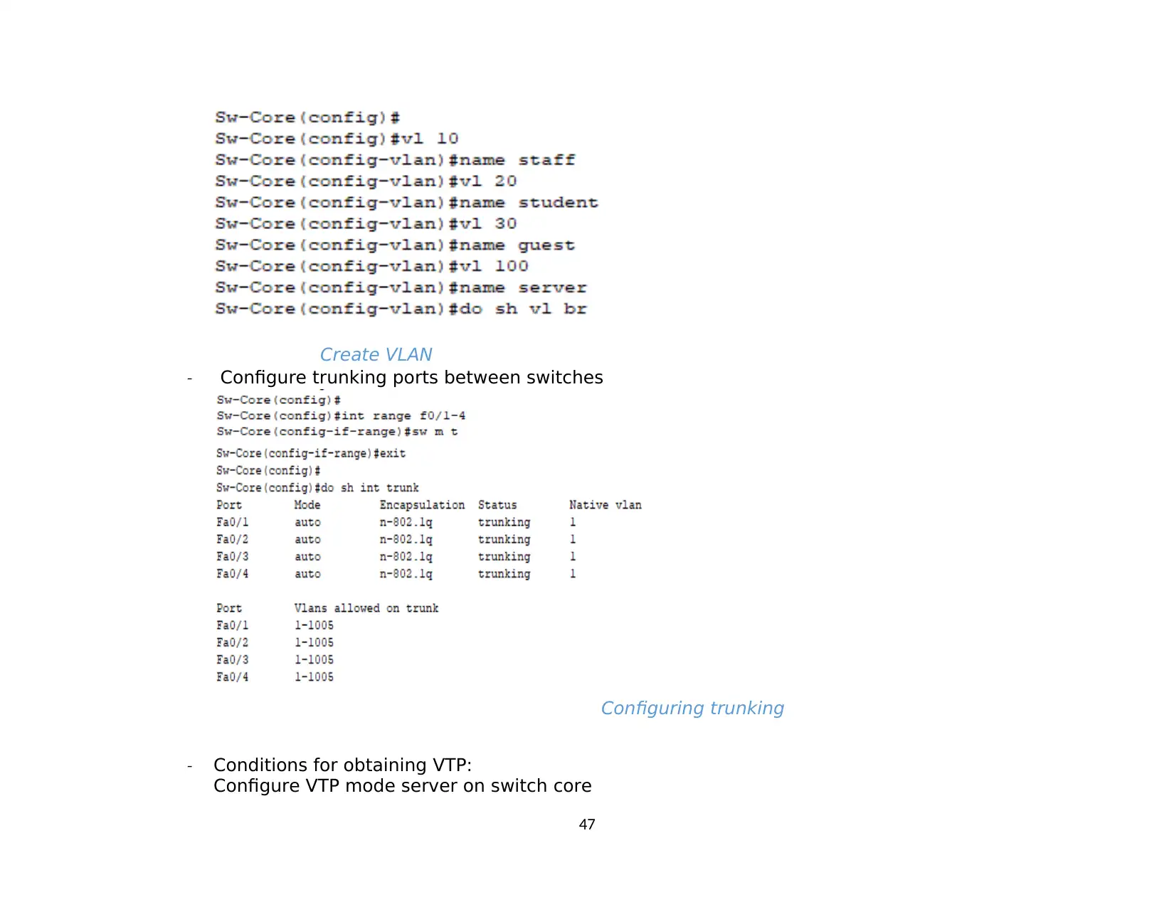
Create VLAN
- Configure trunking ports between switches
Configuring trunking
- Conditions for obtaining VTP:
Configure VTP mode server on switch core
47
- Configure trunking ports between switches
Configuring trunking
- Conditions for obtaining VTP:
Configure VTP mode server on switch core
47
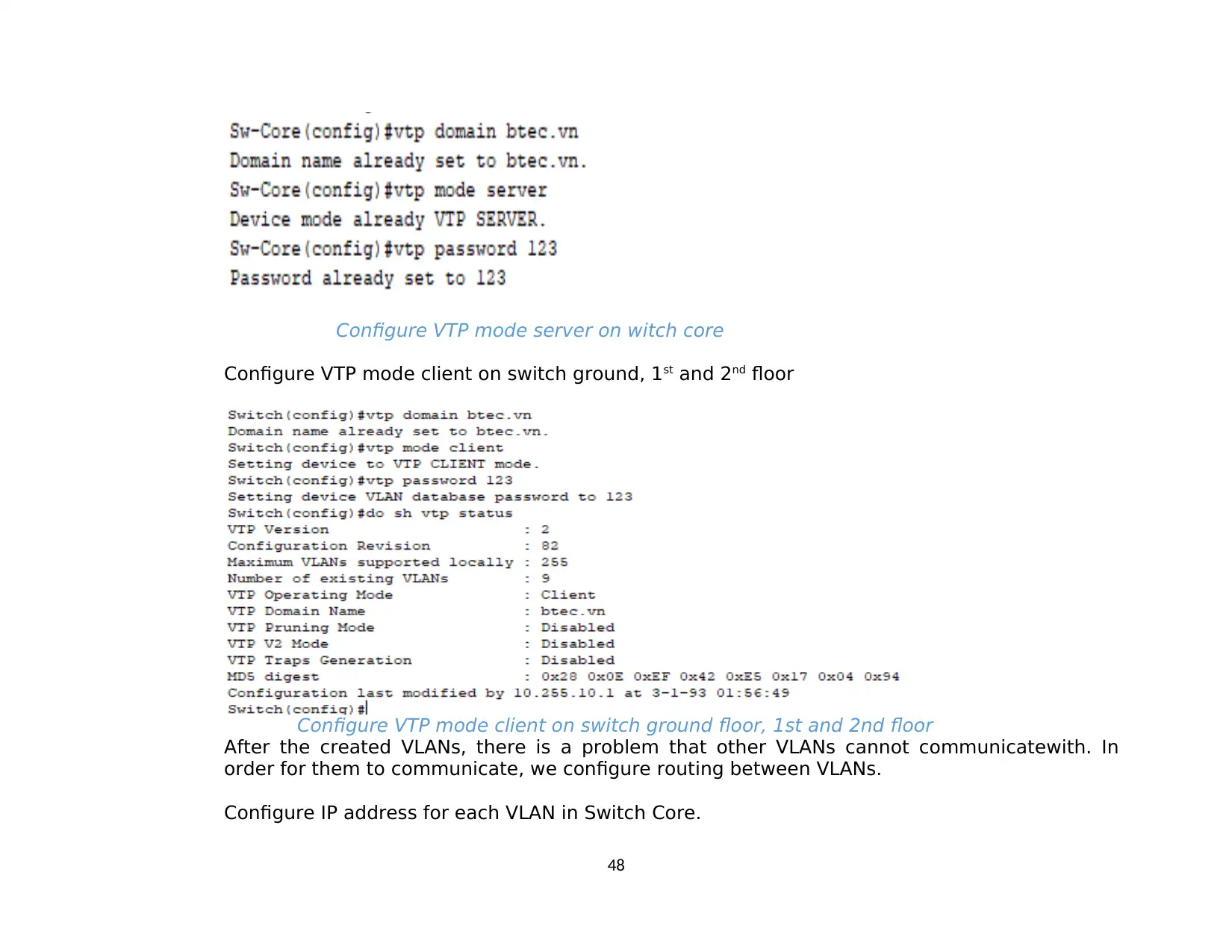
Configure VTP mode server on witch core
Configure VTP mode client on switch ground, 1st and 2nd floor
Configure VTP mode client on switch ground floor, 1st and 2nd floor
After the created VLANs, there is a problem that other VLANs cannot communicatewith. In
order for them to communicate, we configure routing between VLANs.
Configure IP address for each VLAN in Switch Core.
48
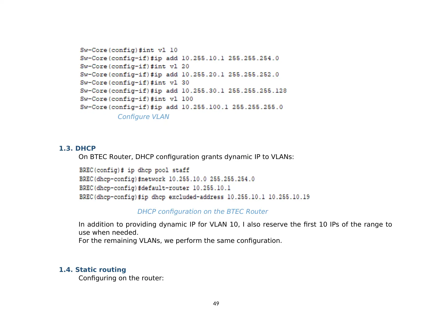
Configure VLAN
1.3. DHCP
On BTEC Router, DHCP configuration grants dynamic IP to VLANs:
DHCP configuration on the BTEC Router
In addition to providing dynamic IP for VLAN 10, I also reserve the first 10 IPs of the range to
use when needed.
For the remaining VLANs, we perform the same configuration.
1.4. Static routing
Configuring on the router:
49
Paraphrase This Document
Need a fresh take? Get an instant paraphrase of this document with our AI Paraphraser
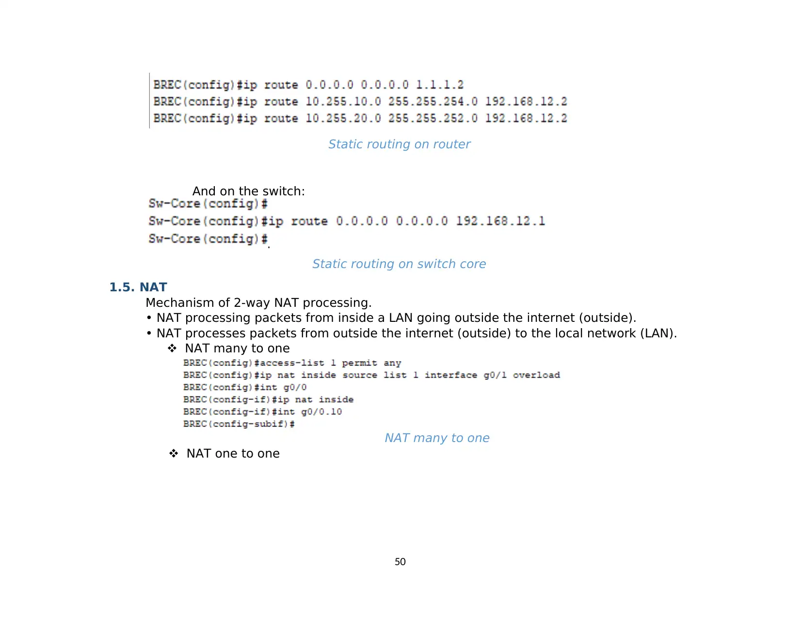
Static routing on router
And on the switch:
Static routing on switch core
1.5. NAT
Mechanism of 2-way NAT processing.
• NAT processing packets from inside a LAN going outside the internet (outside).
• NAT processes packets from outside the internet (outside) to the local network (LAN).
NAT many to one
NAT many to one
NAT one to one
50
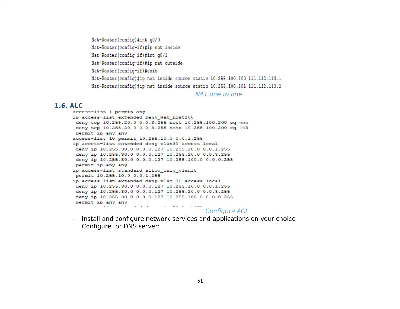
NAT one to one
1.6. ALC
Configure ACL
- Install and configure network services and applications on your choice
Configure for DNS server:
51
1.6. ALC
Configure ACL
- Install and configure network services and applications on your choice
Configure for DNS server:
51
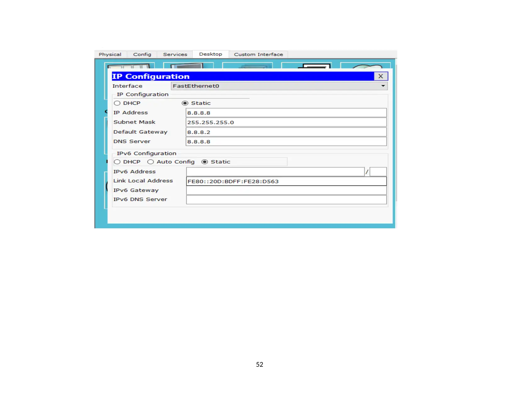
52
Secure Best Marks with AI Grader
Need help grading? Try our AI Grader for instant feedback on your assignments.
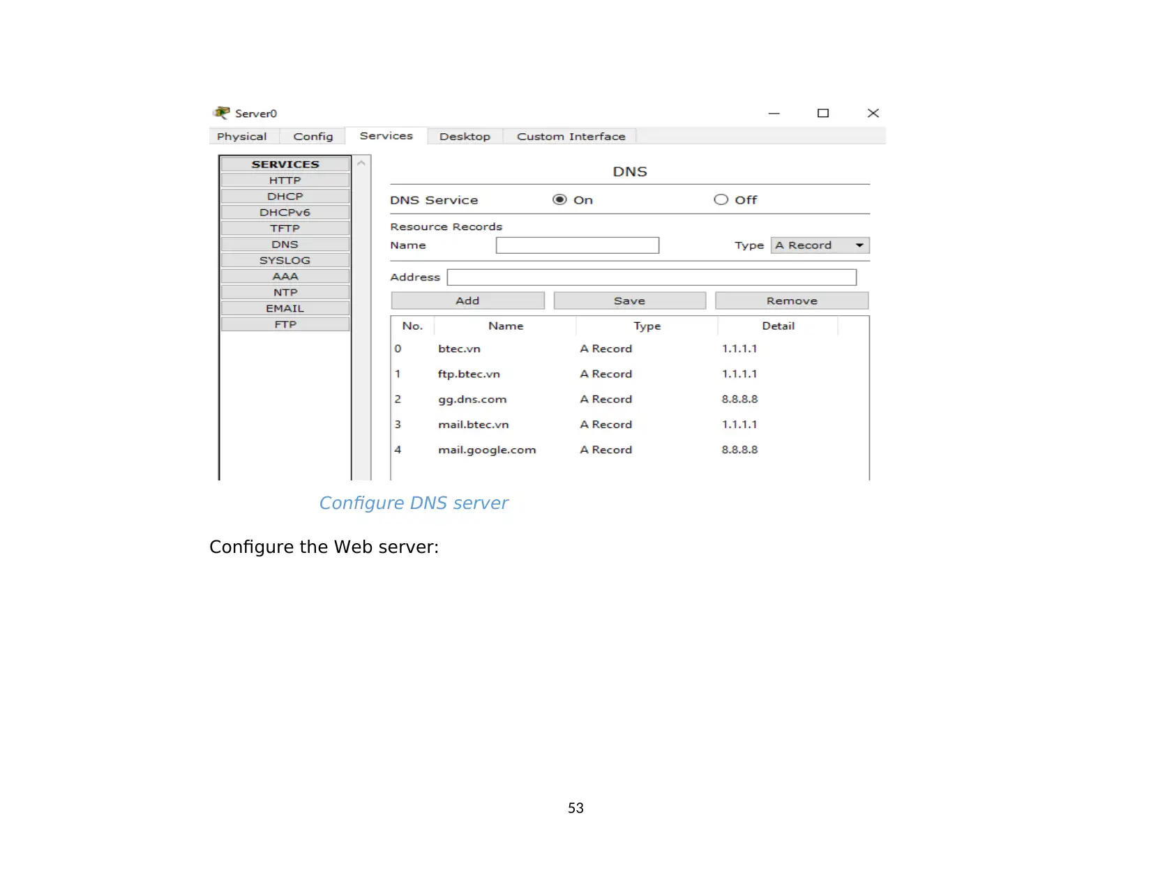
Configure DNS server
Configure the Web server:
53
Configure the Web server:
53
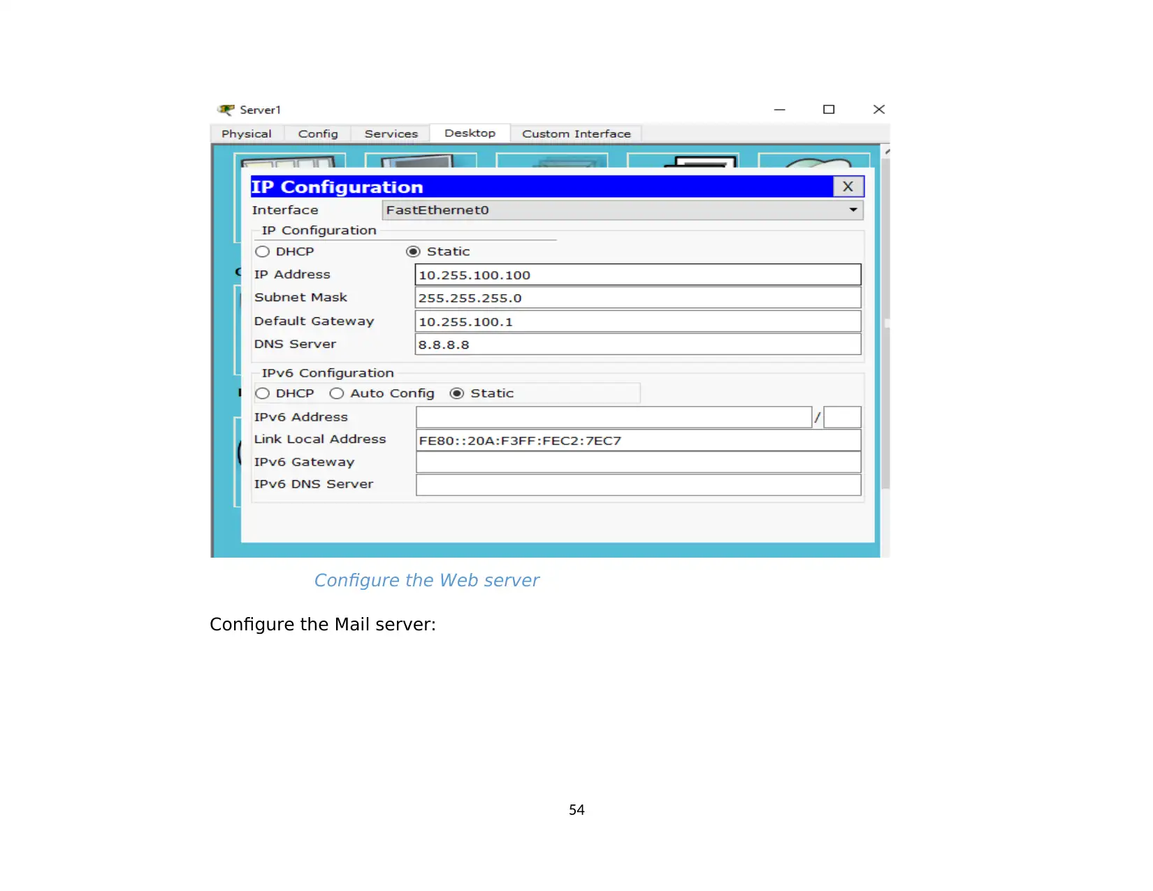
Configure the Web server
Configure the Mail server:
54
Configure the Mail server:
54
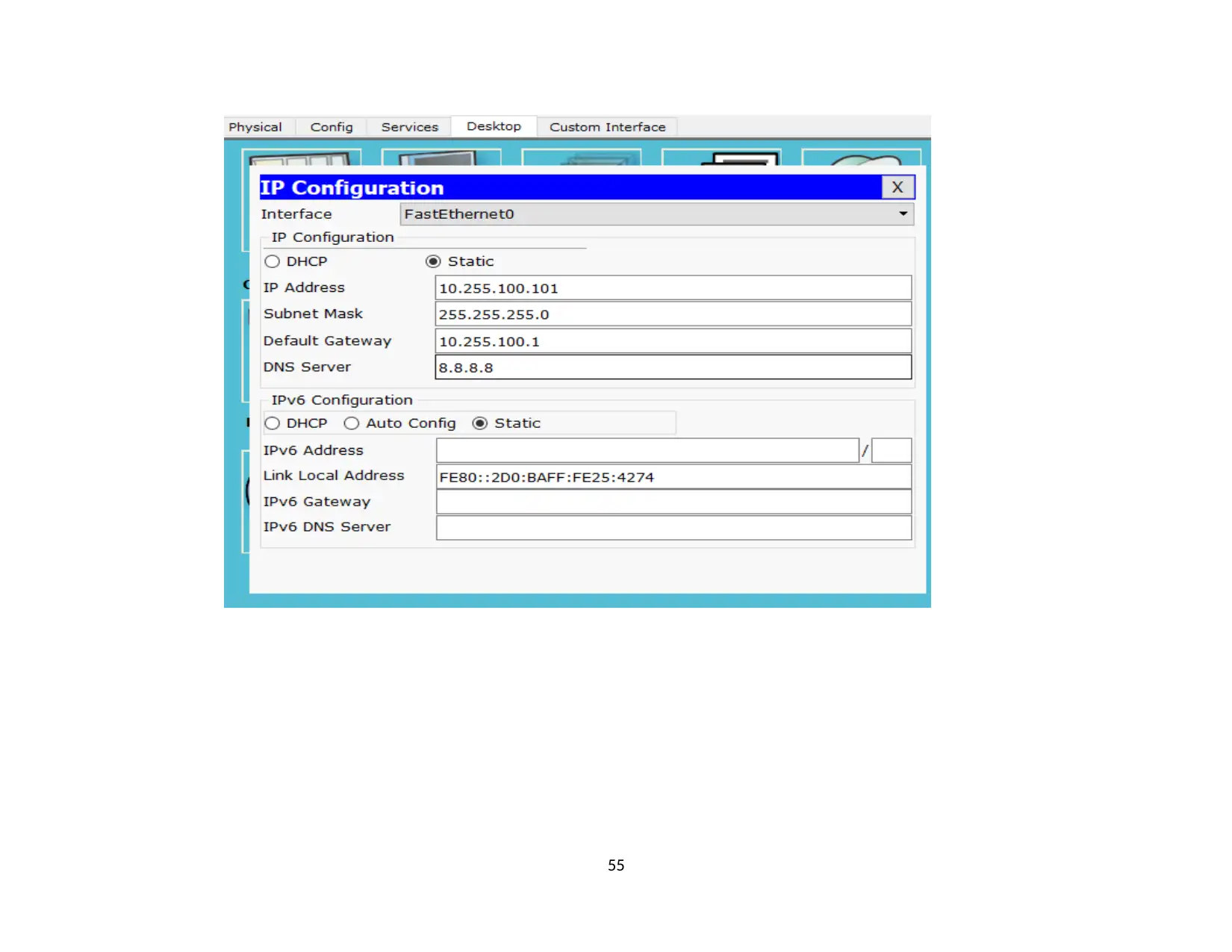
55
Paraphrase This Document
Need a fresh take? Get an instant paraphrase of this document with our AI Paraphraser
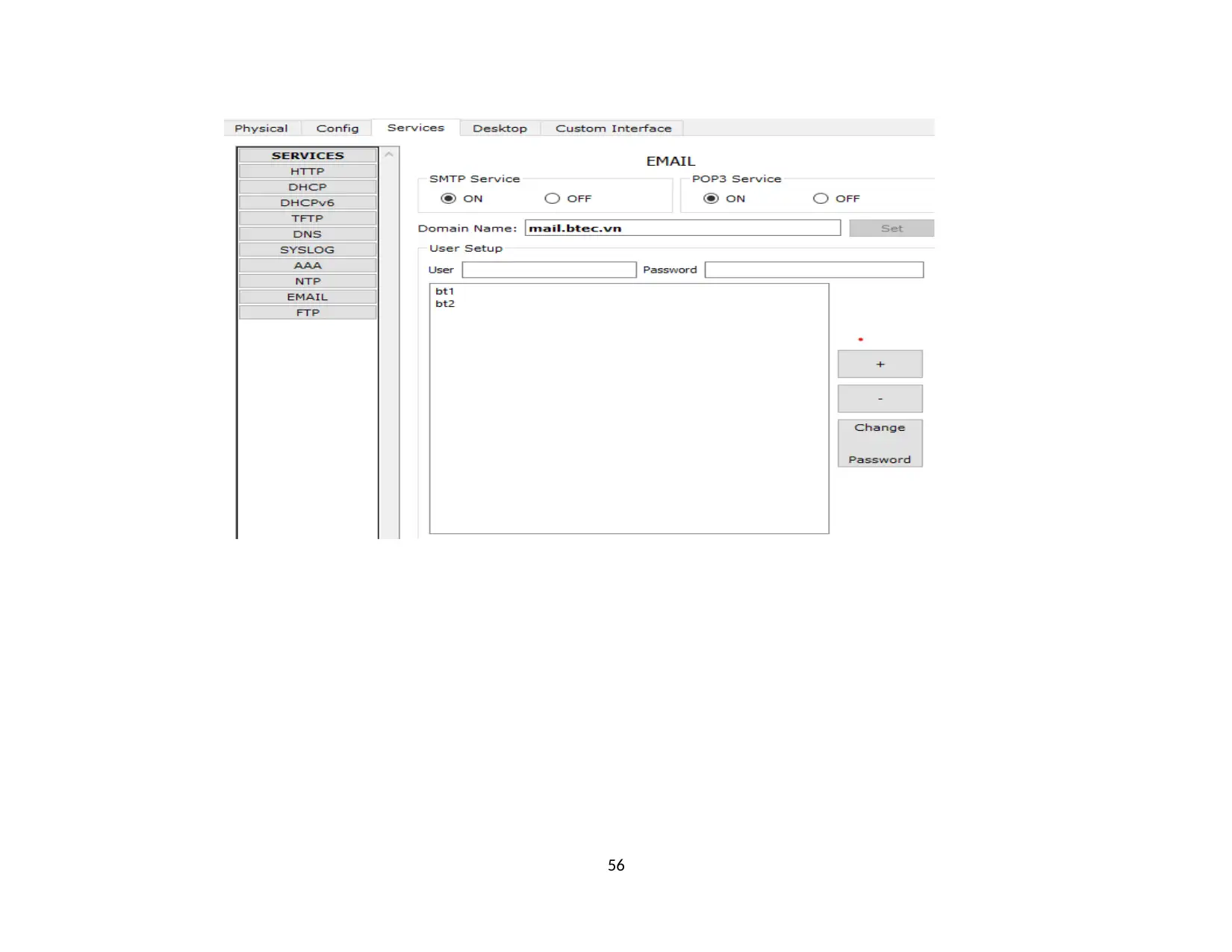
56
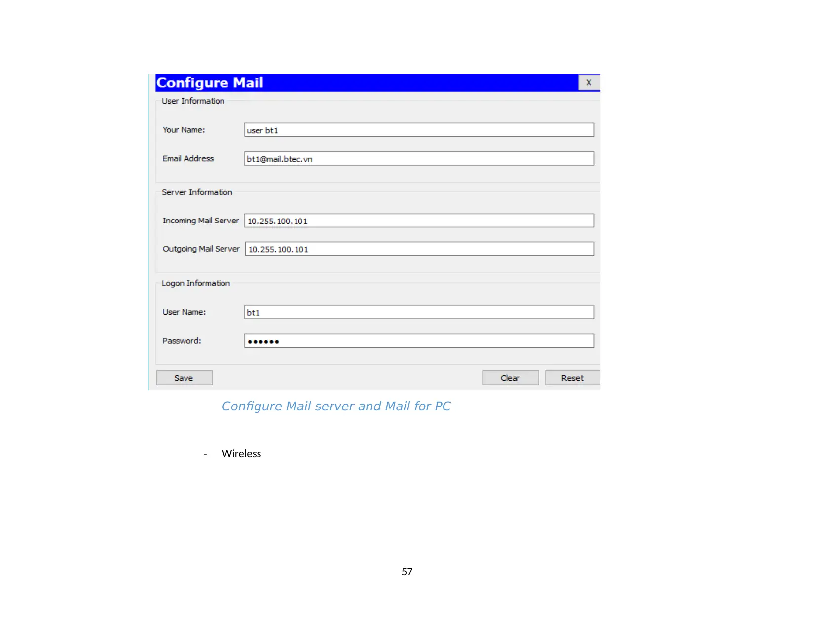
Configure Mail server and Mail for PC
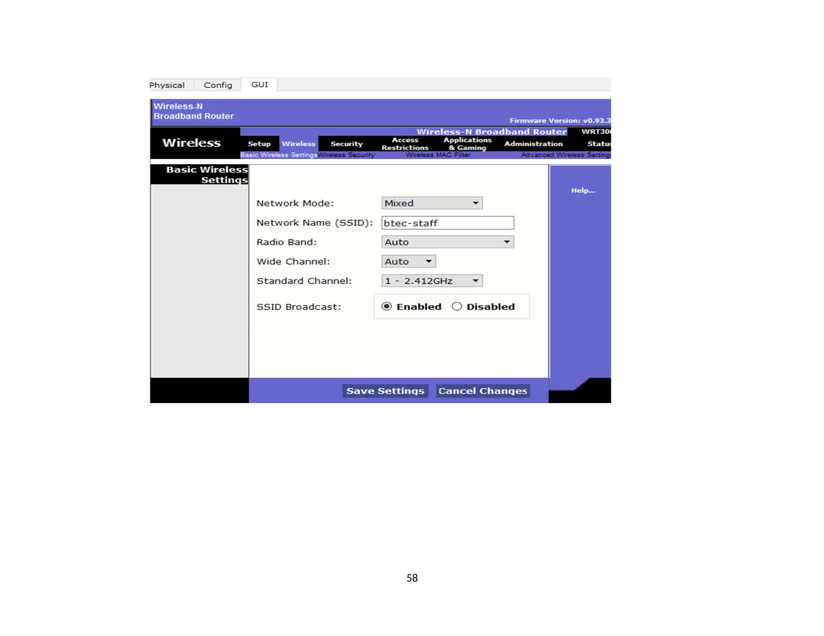
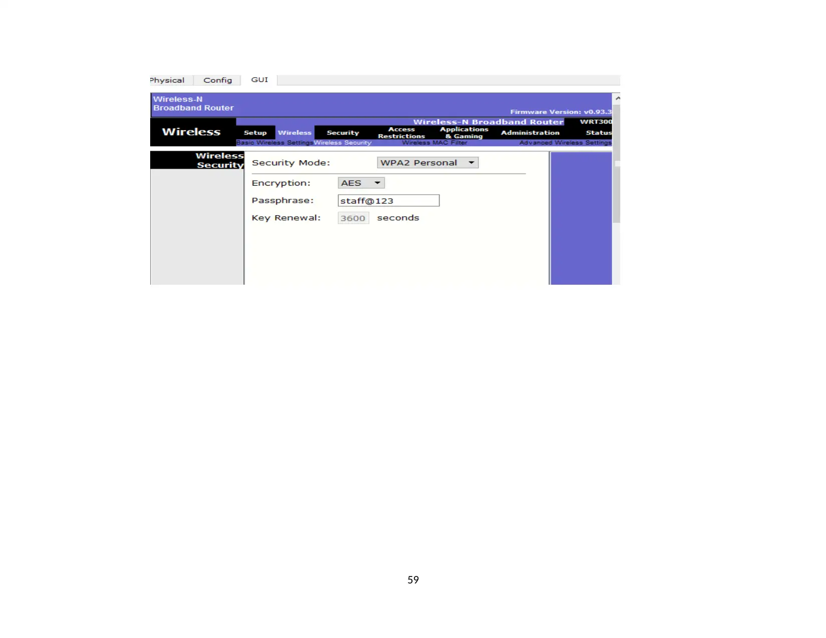
- Wireless
57
- Wireless
57
58
Secure Best Marks with AI Grader
Need help grading? Try our AI Grader for instant feedback on your assignments.
59
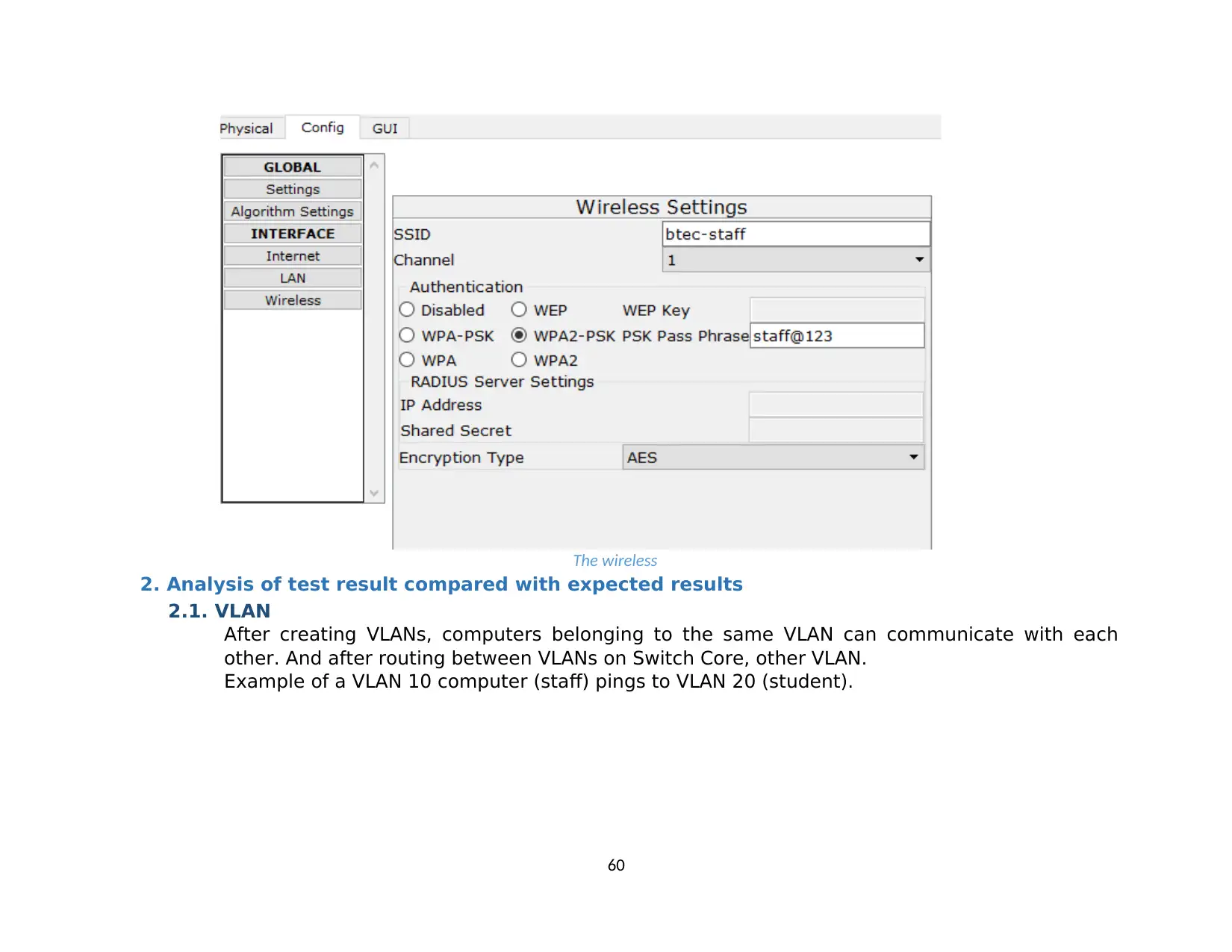
The wireless
2. Analysis of test result compared with expected results
2.1. VLAN
After creating VLANs, computers belonging to the same VLAN can communicate with each
other. And after routing between VLANs on Switch Core, other VLAN.
Example of a VLAN 10 computer (staff) pings to VLAN 20 (student).
60
2. Analysis of test result compared with expected results
2.1. VLAN
After creating VLANs, computers belonging to the same VLAN can communicate with each
other. And after routing between VLANs on Switch Core, other VLAN.
Example of a VLAN 10 computer (staff) pings to VLAN 20 (student).
60
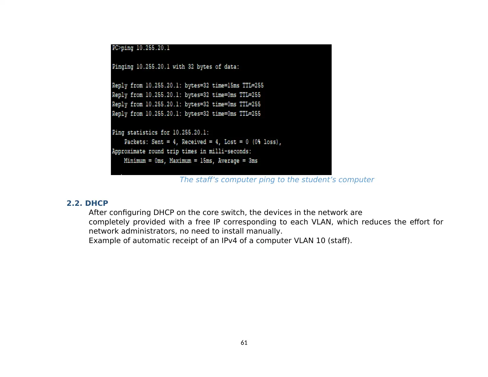
The staff’s computer ping to the student’s computer
2.2. DHCP
After configuring DHCP on the core switch, the devices in the network are
completely provided with a free IP corresponding to each VLAN, which reduces the effort for
network administrators, no need to install manually.
Example of automatic receipt of an IPv4 of a computer VLAN 10 (staff).
61
Paraphrase This Document
Need a fresh take? Get an instant paraphrase of this document with our AI Paraphraser
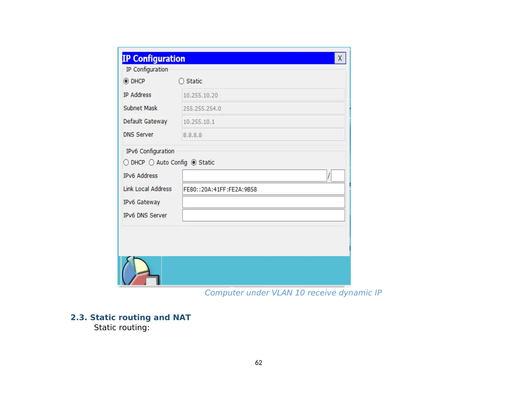
Computer under VLAN 10 receive dynamic IP
2.3. Static routing and NAT
Static routing:
62
2.3. Static routing and NAT
Static routing:
62
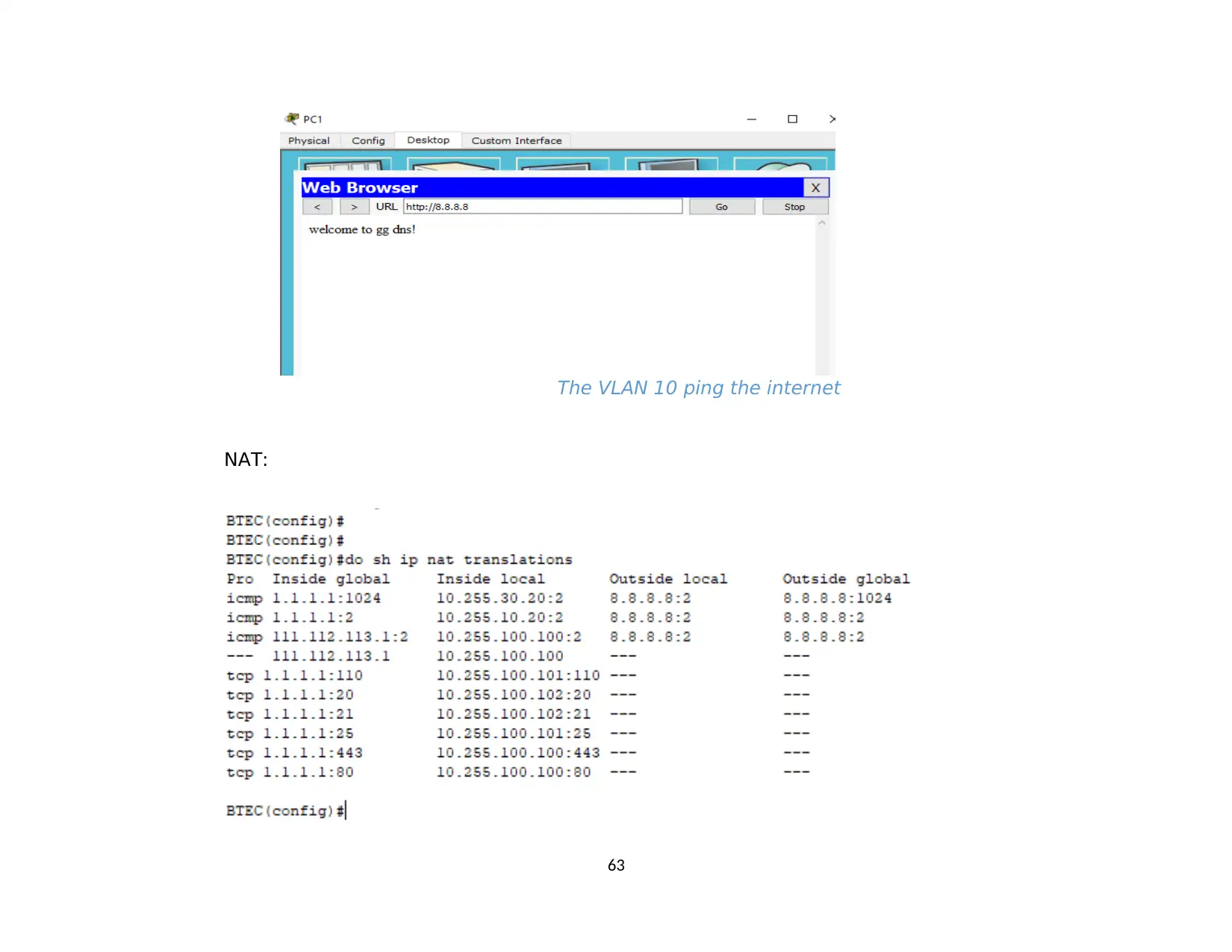
The VLAN 10 ping the internet
NAT:
63
NAT:
63
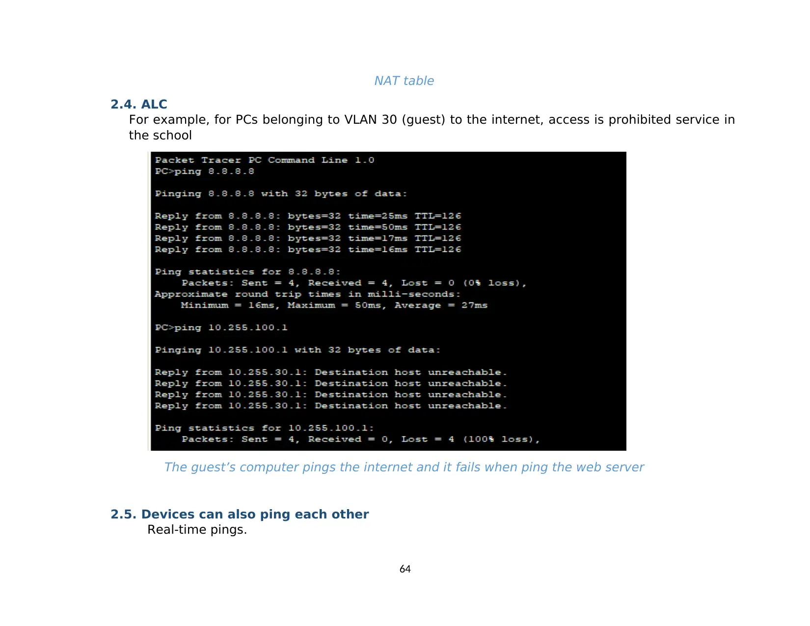
NAT table
2.4. ALC
For example, for PCs belonging to VLAN 30 (guest) to the internet, access is prohibited service in
the school
The guest’s computer pings the internet and it fails when ping the web server
2.5. Devices can also ping each other
Real-time pings.
64
2.4. ALC
For example, for PCs belonging to VLAN 30 (guest) to the internet, access is prohibited service in
the school
The guest’s computer pings the internet and it fails when ping the web server
2.5. Devices can also ping each other
Real-time pings.
64
Secure Best Marks with AI Grader
Need help grading? Try our AI Grader for instant feedback on your assignments.
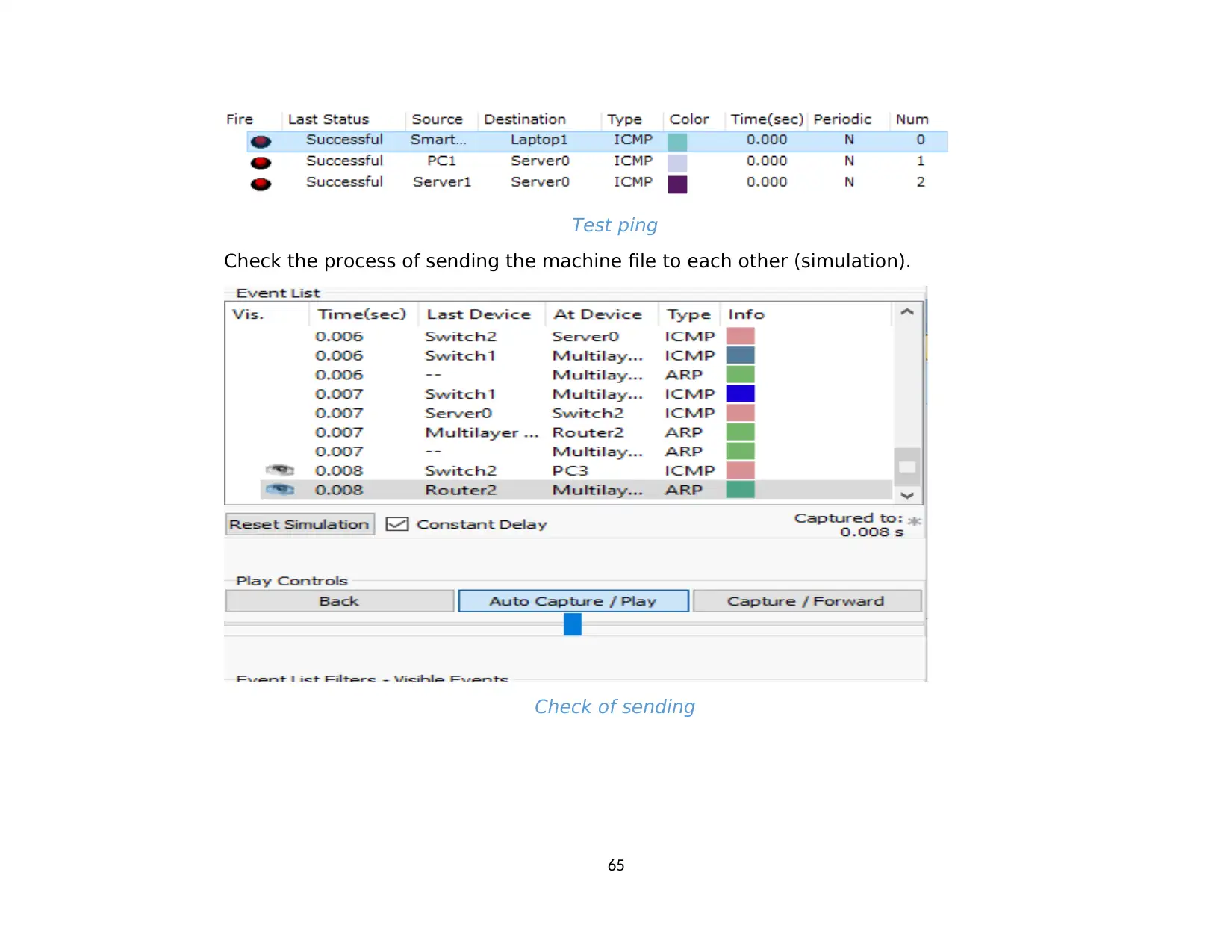
Test ping
Check the process of sending the machine file to each other (simulation).
Check of sending
65
Check the process of sending the machine file to each other (simulation).
Check of sending
65
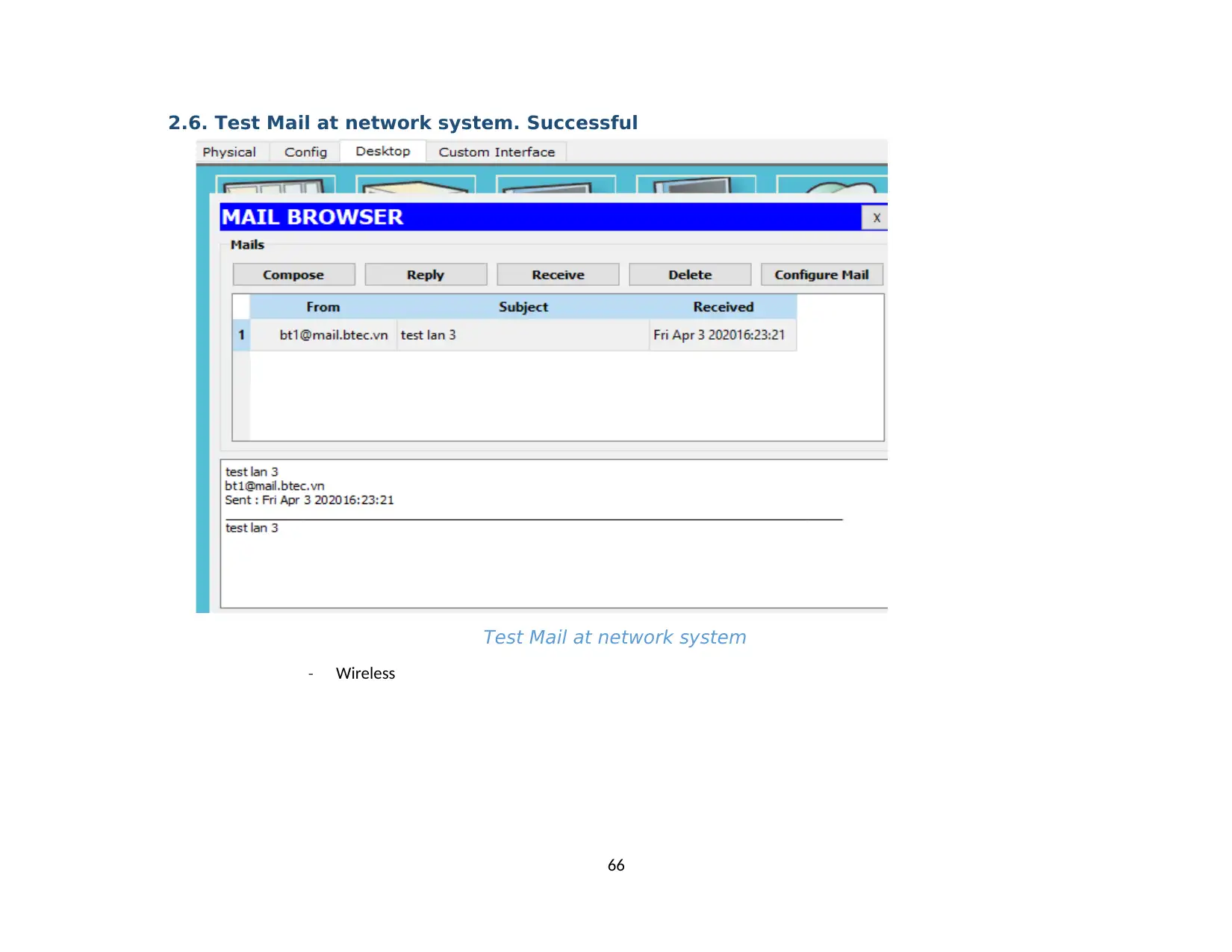
2.6. Test Mail at network system. Successful
Test Mail at network system
- Wireless
66
Test Mail at network system
- Wireless
66
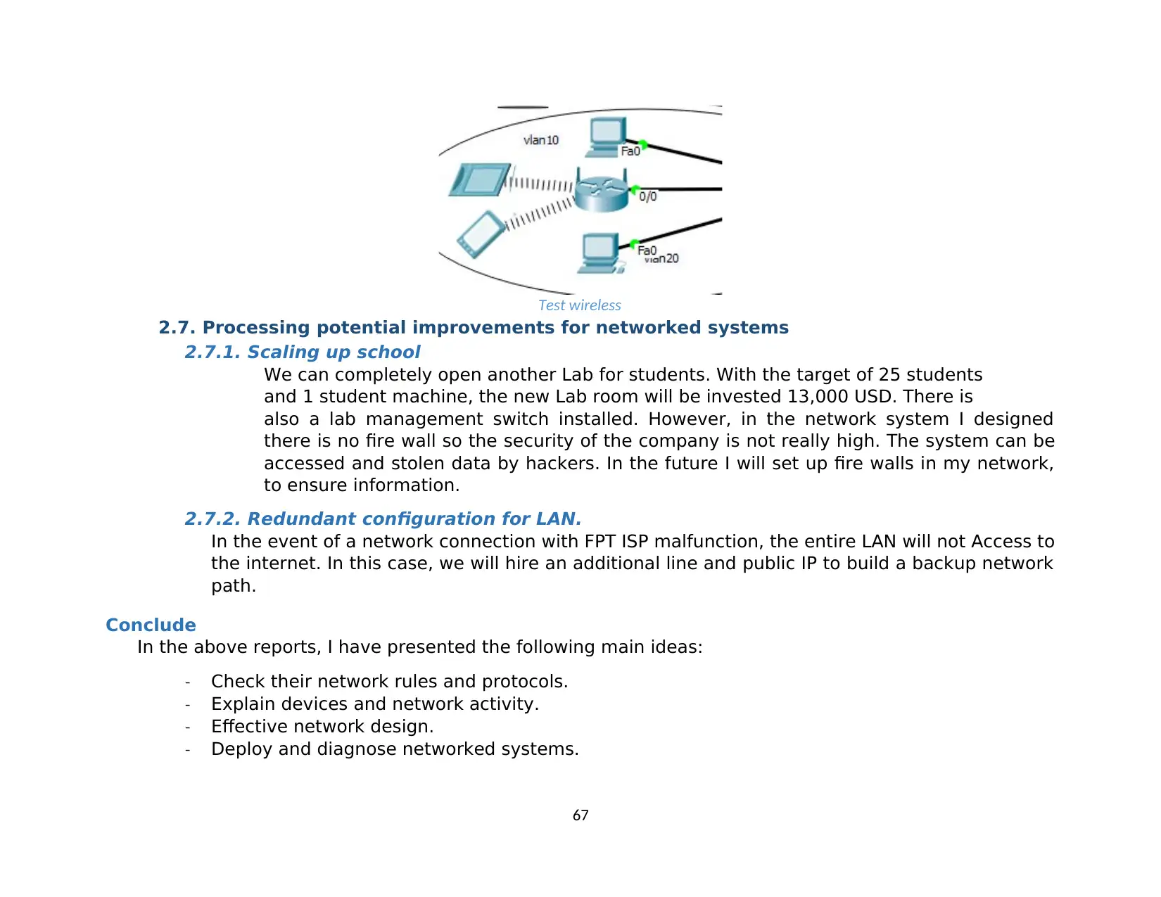
Test wireless
2.7. Processing potential improvements for networked systems
2.7.1. Scaling up school
We can completely open another Lab for students. With the target of 25 students
and 1 student machine, the new Lab room will be invested 13,000 USD. There is
also a lab management switch installed. However, in the network system I designed
there is no fire wall so the security of the company is not really high. The system can be
accessed and stolen data by hackers. In the future I will set up fire walls in my network,
to ensure information.
2.7.2. Redundant configuration for LAN.
In the event of a network connection with FPT ISP malfunction, the entire LAN will not Access to
the internet. In this case, we will hire an additional line and public IP to build a backup network
path.
Conclude
In the above reports, I have presented the following main ideas:
- Check their network rules and protocols.
- Explain devices and network activity.
- Effective network design.
- Deploy and diagnose networked systems.
67
Paraphrase This Document
Need a fresh take? Get an instant paraphrase of this document with our AI Paraphraser
References
Alam, M., 2014. Advantages and Disadvantages of LAN Local Area Network. [Online].
Alexander, 2016. What are OSI and TCP/IP?. [Online] Available at:
https://www.swissns.ch/site/2016/11/what-are-osi-and-tcpip/
Anon., 2015. Network-LAN-WAN Solution. [Online] Available at: http://uranus.com.vn/solutions/Giai-
phap-mang-LAN-WAN/Mo-hinh-mang-cho-cac-doanh- nghiep-vua-va-nho-9/
Anon., 2017. Get started with Visual Studio 2017. [Online].
Anon., n.d. Wire Area Network. [Online] Available at: https://metricloop.com/library/network
Tech, N., 2018. What is DNS server? Types of name server? google DNS- by nearly tech. [Online] Available at:
https://www.nearlytech.com/2018/06/what-is-dns-server-types-of-name-server.html
Tutorial, S., 2018. The Relationship Between Hardware and Software. [Online].
WordPress, J. R. D., 2016. What are the different types of servers? [Online] Available at: https://www.quora.com/What-are-
the-different-types-of-servers
Computer network devices, router, repeaters, gateway, bridge, and hub. Available at: https://t4tutorials.com/computer-network-
devices-router-repeaters-gateway-bridge-an
LAN Card or WIFI Card (NIC) – What It Is & Why We Need It?. Available at: https://www.deskdecode.com/lan-card-or-wifi-card-nic/
68
1 out of 68
Related Documents
Your All-in-One AI-Powered Toolkit for Academic Success.
+13062052269
info@desklib.com
Available 24*7 on WhatsApp / Email
![[object Object]](/_next/static/media/star-bottom.7253800d.svg)
Unlock your academic potential
© 2024 | Zucol Services PVT LTD | All rights reserved.


