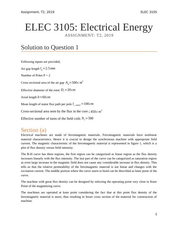
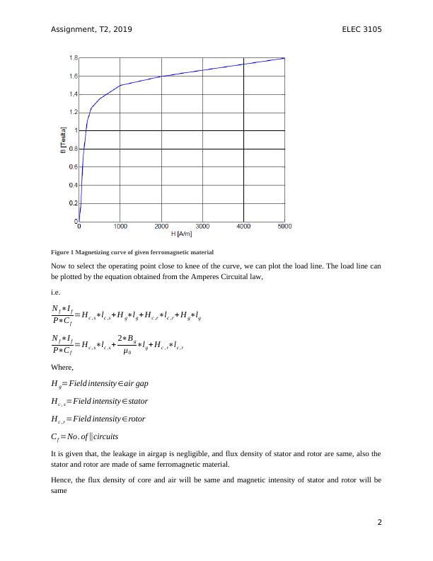
Magnetic Circuits of AC Machines: Analysis and Derivations
This assignment is for the course ELEC3105: Electrical Energy. It is worth 10% of the final marks and must be uploaded as a PDF file on Moodle by 11:59 pm on Monday, 12 August. The assignment assesses the student's ability to select and design power engineering devices for real-life applications.
12 Pages1717 Words373 Views
Added on 2022-10-12
About This Document
This assignment focuses on understanding the magnetic circuits of ac machines. The assignment involves the study of mmf, flux density, B-H curve, energy stored in air gap and magnetism of electrical ac machines.
Magnetic Circuits of AC Machines: Analysis and Derivations
This assignment is for the course ELEC3105: Electrical Energy. It is worth 10% of the final marks and must be uploaded as a PDF file on Moodle by 11:59 pm on Monday, 12 August. The assignment assesses the student's ability to select and design power engineering devices for real-life applications.
Added on 2022-10-12
ShareRelated Documents
End of preview
Want to access all the pages? Upload your documents or become a member.
Synchronous Machines - Types, Operation, Phasor Diagram, Torque and Power
|3
|535
|313