logo

Synchronous Machines - Types, Operation, Phasor Diagram, Torque and Power

Learn about FACTS Devices such as SVC and STATCOM and HVDC (high voltage DC) system

3 Pages535 Words313 Views
   

Added on  2022-11-18

About This Document

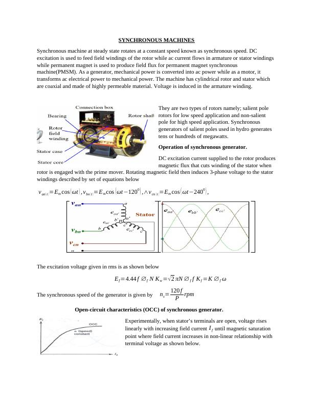
Synchronous machines are used as generators and motors. They have cylindrical rotor and stator made of highly permeable material. Learn about the types of rotors, operation of synchronous generator, open-circuit characteristics, equivalent circuit model, phasor diagram, torque and power, parallel operation of synchronous generators, voltage regulation characteristics of a standalone synchronous generator and synchronous condenser.

Synchronous Machines - Types, Operation, Phasor Diagram, Torque and Power

Learn about FACTS Devices such as SVC and STATCOM and HVDC (high voltage DC) system

   Added on 2022-11-18

ShareRelated Documents
SYNCHRONOUS MACHINES
Synchronous machine at steady state rotates at a constant speed known as synchronous speed. DC
excitation is used to feed field windings of the rotor while ac current flows in armature or stator windings
while permanent magnet is used to produce field flux for permanent magnet synchronous
machine(PMSM). As a generator, mechanical power is converted into ac power while as a motor, it
transforms ac electrical power to mechanical power. The machine has cylindrical rotor and stator which
are coaxial and made of highly permeable material. Voltage is induced in the armature winding.
They are two types of rotors namely; salient pole
rotors for low speed application and non-salient
pole for high speed application. Synchronous
generators of salient poles used in hydro generates
tens or hundreds of megawatts.
Operation of synchronous generator.
DC excitation current supplied to the rotor produces
magnetic flux that cuts winding of the stator when
rotor is engaged with the prime mover. Rotating magnetic field then induces 3-phase voltage to the stator
windings described by set of equations below
van ( t ) =Em cos ( ωt ) , vbn ( t ) =Em cos ( ωt1200 ) ,vcn ( t ) =Em cos ( ωt2400 ) ,
The excitation voltage given in rms is as shown below
Ef =4.44 f f N Kw = 2 πN f f Kf =K f ω
The synchronous speed of the generator is given by ns= 120 f
P rpm
Open-circuit characteristics (OCC) of synchronous generator.
Experimentally, when stator’s terminals are open, voltage rises
linearly with increasing field current I f until magnetic saturation
point where field current increases in non-linear relationship with
terminal voltage as shown below.
Synchronous Machines - Types, Operation, Phasor Diagram, Torque and Power_1

End of preview

Want to access all the pages? Upload your documents or become a member.

Related Documents
Theoretical Background Electrical Engineering
|9
|1452
|51

Power Electronics : Assignment
|3
|729
|162

Transformer and Induction Motor Tests and Analysis
|11
|927
|438

DC Motor Depth Study-Report
|10
|2241
|446

Classifications of DC Motors
|15
|1933
|121

Types and Construction of Generators
|7
|718
|109