Comprehensive Report: 3-Band Audio Amplifier Design and Analysis
VerifiedAdded on 2022/09/15
|33
|5764
|17
Report
AI Summary
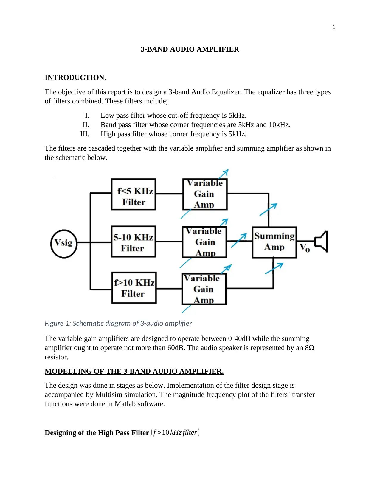
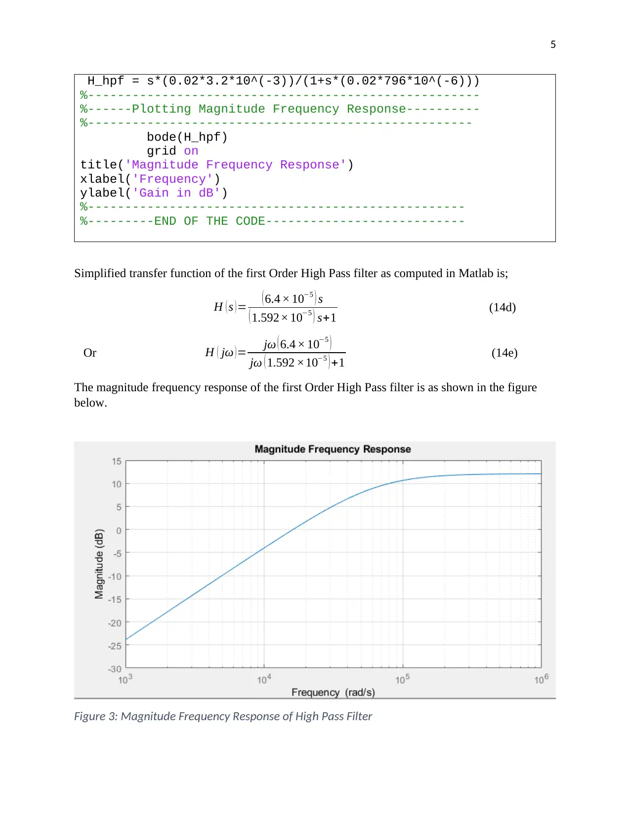
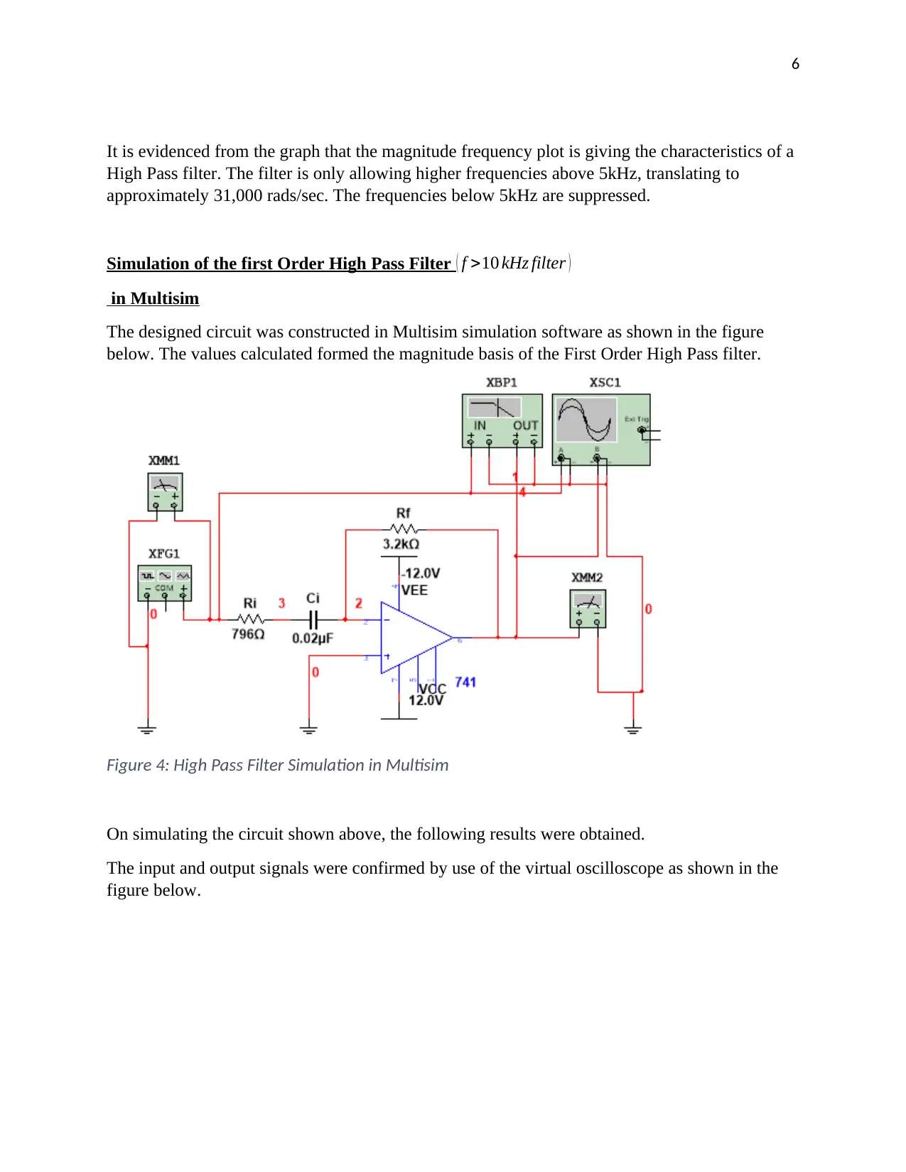
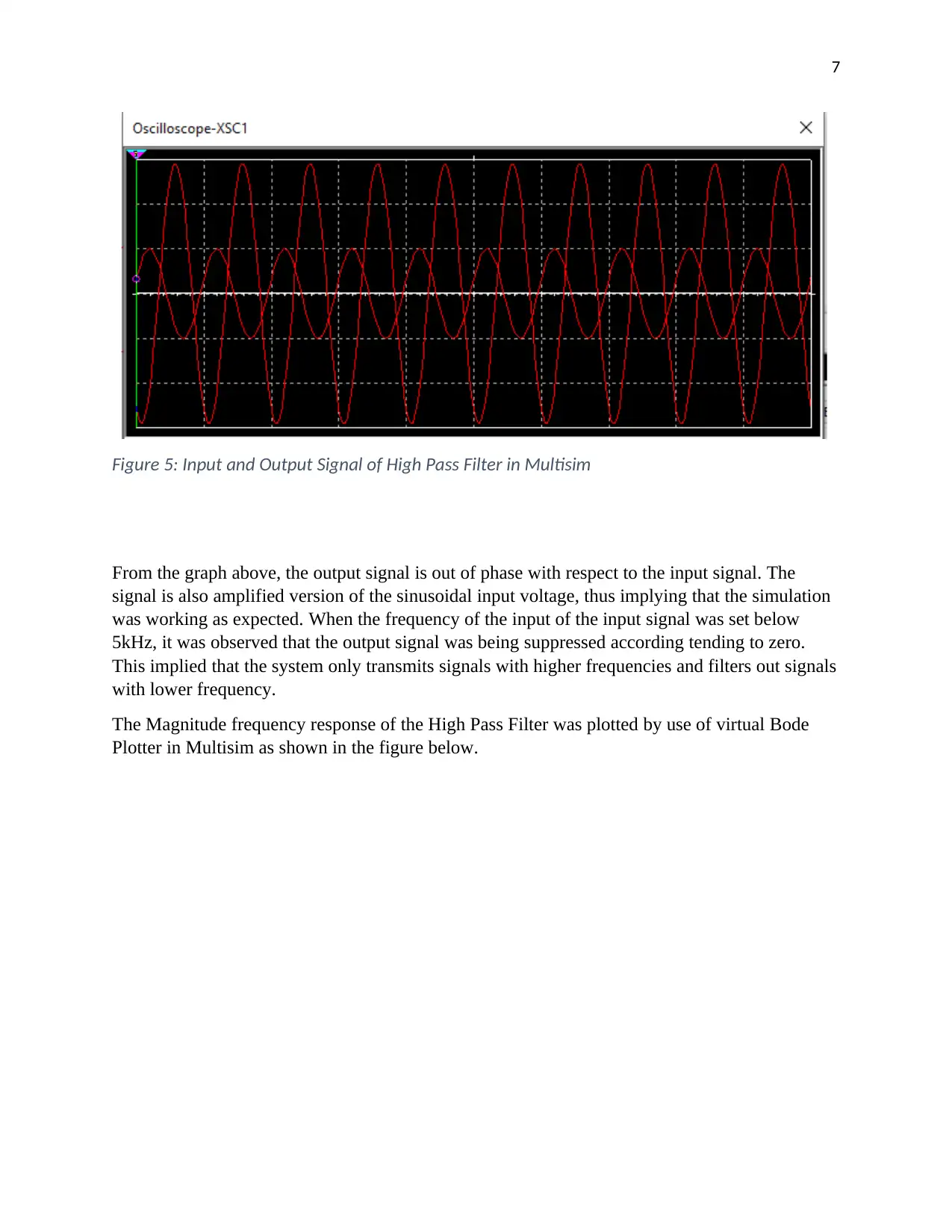
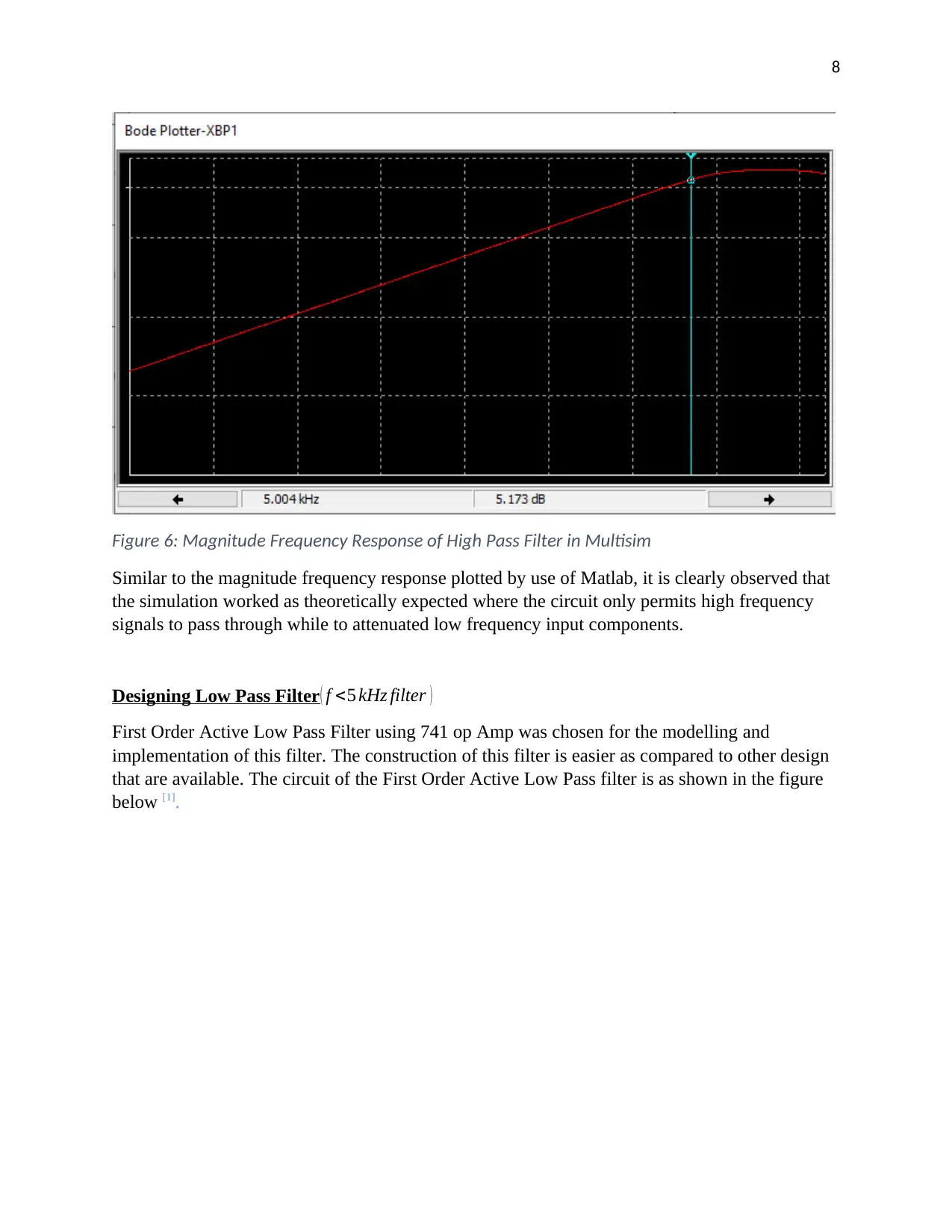
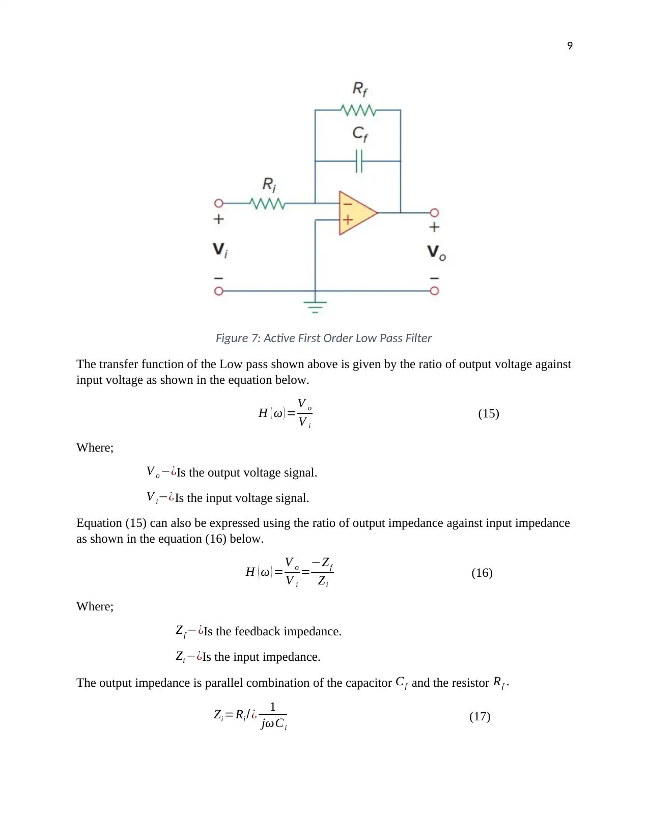
This report details the design and implementation of a 3-band audio amplifier, which functions as an audio equalizer. The design incorporates three filter types: a low-pass filter with a 5kHz cutoff, a band-pass filter with 5kHz and 10kHz corner frequencies, and a high-pass filter with a 5kHz corner frequency. The filters are cascaded with variable and summing amplifiers, with the variable gain amplifiers designed to operate between 0-40dB and the summing amplifier not exceeding 60dB. The design process involved stages of filter design, accompanied by Multisim simulations, and magnitude frequency plots of the filters' transfer functions were generated using MATLAB. The report includes detailed explanations of the design process for each filter, along with mathematical expressions, transfer functions, and simulation results. The report also presents the MATLAB code used for generating the magnitude frequency responses and provides graphical representations of the filters' performance characteristics.
1 out of 33
Related Documents


Your All-in-One AI-Powered Toolkit for Academic Success.
+13062052269
info@desklib.com
Available 24*7 on WhatsApp / Email
![[object Object]](/_next/static/media/star-bottom.7253800d.svg)
Copyright © 2020–2026 A2Z Services. All Rights Reserved. Developed and managed by ZUCOL.