logo

Room Temperature Control System Analysis


Added on  2020-04-13

11 Pages2413 Words51 Views
 | 
 | 
 | 
BRUNEL UNIVERSITY
MSc in Building Services Engineering
Building Management and Control Systems
CONTROL SYSTEMS ASSIGNMENT 2017/18
Student Name
Student Registration Number
Course Code
Date of submission
Room Temperature Control System Analysis_1

Introduction
A control system consists of interconnected components designed to achieve a desired
purpose. Some of the modern control engineering practice includes the use of control design
strategies for the improvement of manufacturing processes, the efficiency of energy use,
advanced automobile control, as well as rapid transit. The control of the heating of a room
forming the basis of the control system. The thermal response of a particular room was modelled
as a first order system with a time constant of 20 minutes. Control systems are used to determine
the inputs to a system and they equally govern the outputs as intended (Basilio, 2002). There are
two types of control, the open and closed loop control. The open loop control does not have a
feedback section in the system. There is no way to monitor the process to find out if the output is
obtained as intended. The controller in an open loop system may operate an actuator or a switch
to adjust the input to the process. The closed loop control system, on the other hand, has a
feedback system. The feedback system can be positive or negative depending on the design of
the system (Ogata, n.d).
This assignment seeks to find out more information on how to control the heating of a
room using a radiator. The radiator should get inputs from the surrounding and the controller
adjusts the temperature according to the room heat requirements. The control engineers are often
faced with the central problem in control of finding a technically feasible way to act on a given
process so that the process behaves as closely as possible to the desired behavior. The
approximate behavior should be achieved in the face of uncertainty of the process and in the
presence of uncontrollable external disturbances acting on the process. The major objectives of
the controller design are to achieve speed, accuracy and system stability (Wang, n.d.).
Assumption
(i) The heating of the room is achieved using a LPHW panel radiator.
(ii) The room temperature was regulated using an electric heater of variable output W
watts.
(iii) The heat output from this radiator can be controlled by adjusting the LPHW flow rate.
(iv) The relationship between the flow rate and the radiator output can be approximately
by a first order transfer function with a time constant of one minute.
PART 1: OPEN LOOP
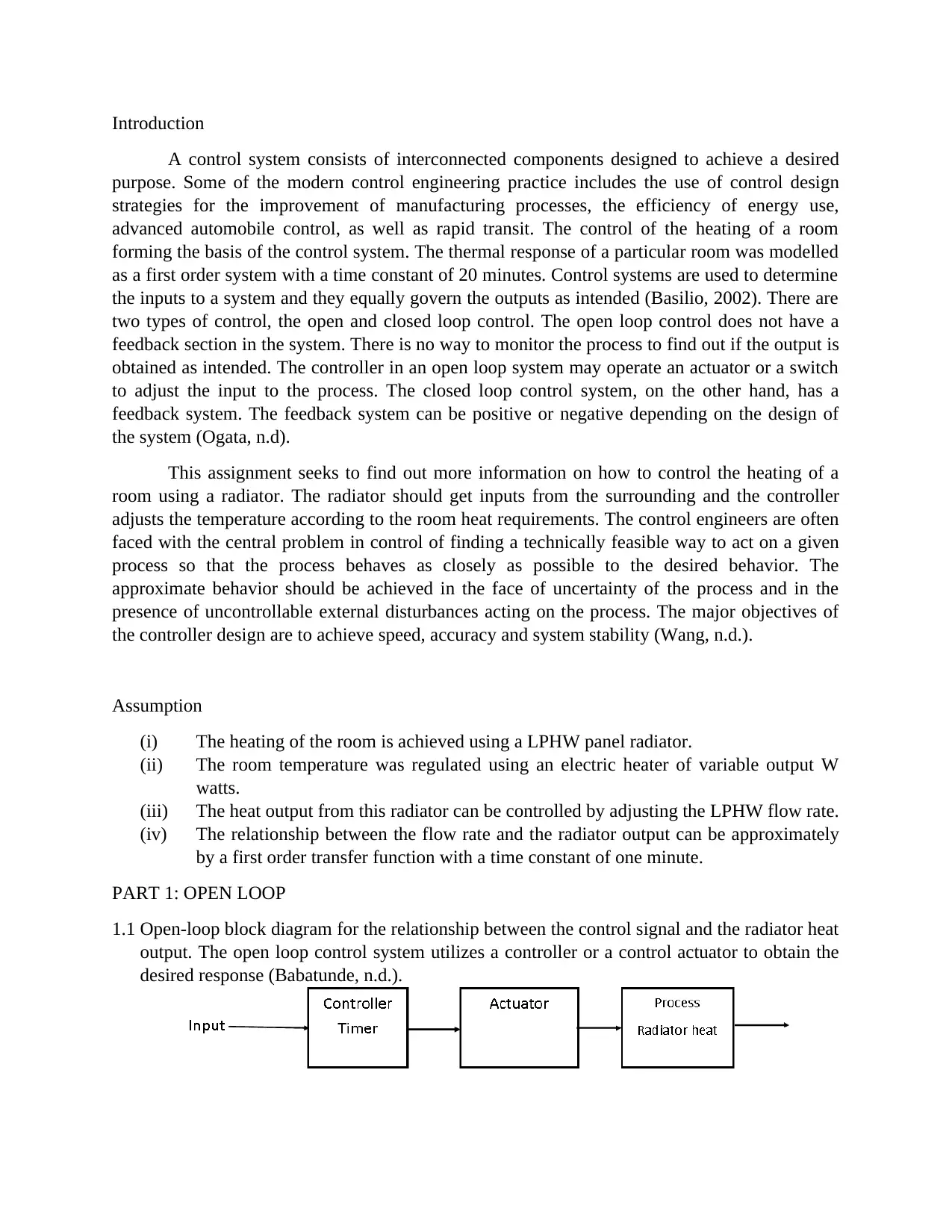
1.1 Open-loop block diagram for the relationship between the control signal and the radiator heat
output. The open loop control system utilizes a controller or a control actuator to obtain the
desired response (Babatunde, n.d.).
Room Temperature Control System Analysis_2

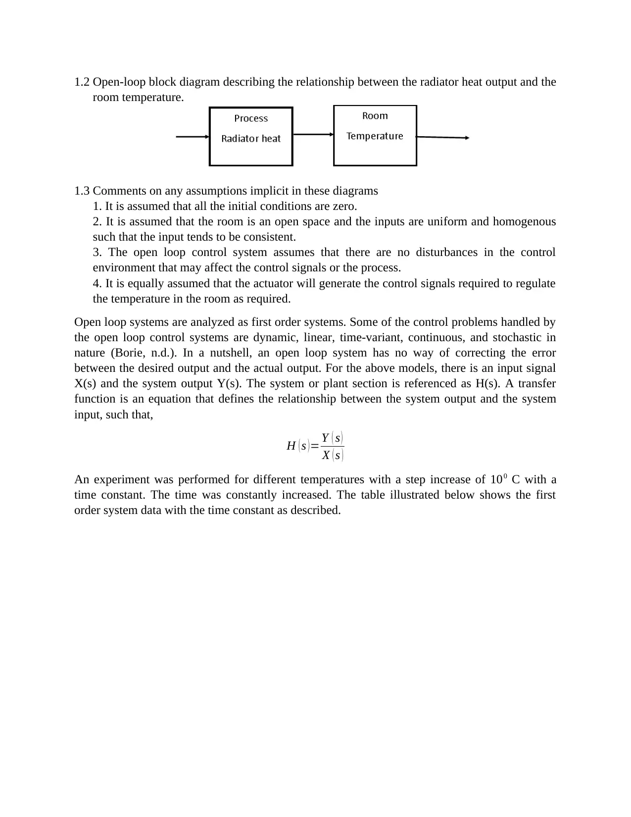
1.2 Open-loop block diagram describing the relationship between the radiator heat output and the
room temperature.
1.3 Comments on any assumptions implicit in these diagrams
1. It is assumed that all the initial conditions are zero.
2. It is assumed that the room is an open space and the inputs are uniform and homogenous
such that the input tends to be consistent.
3. The open loop control system assumes that there are no disturbances in the control
environment that may affect the control signals or the process.
4. It is equally assumed that the actuator will generate the control signals required to regulate
the temperature in the room as required.
Open loop systems are analyzed as first order systems. Some of the control problems handled by
the open loop control systems are dynamic, linear, time-variant, continuous, and stochastic in
nature (Borie, n.d.). In a nutshell, an open loop system has no way of correcting the error
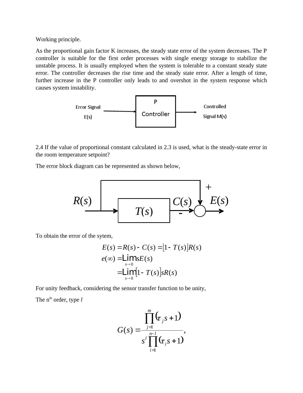
between the desired output and the actual output. For the above models, there is an input signal
X(s) and the system output Y(s). The system or plant section is referenced as H(s). A transfer
function is an equation that defines the relationship between the system output and the system
input, such that,
H ( s )= Y ( s )
X ( s )
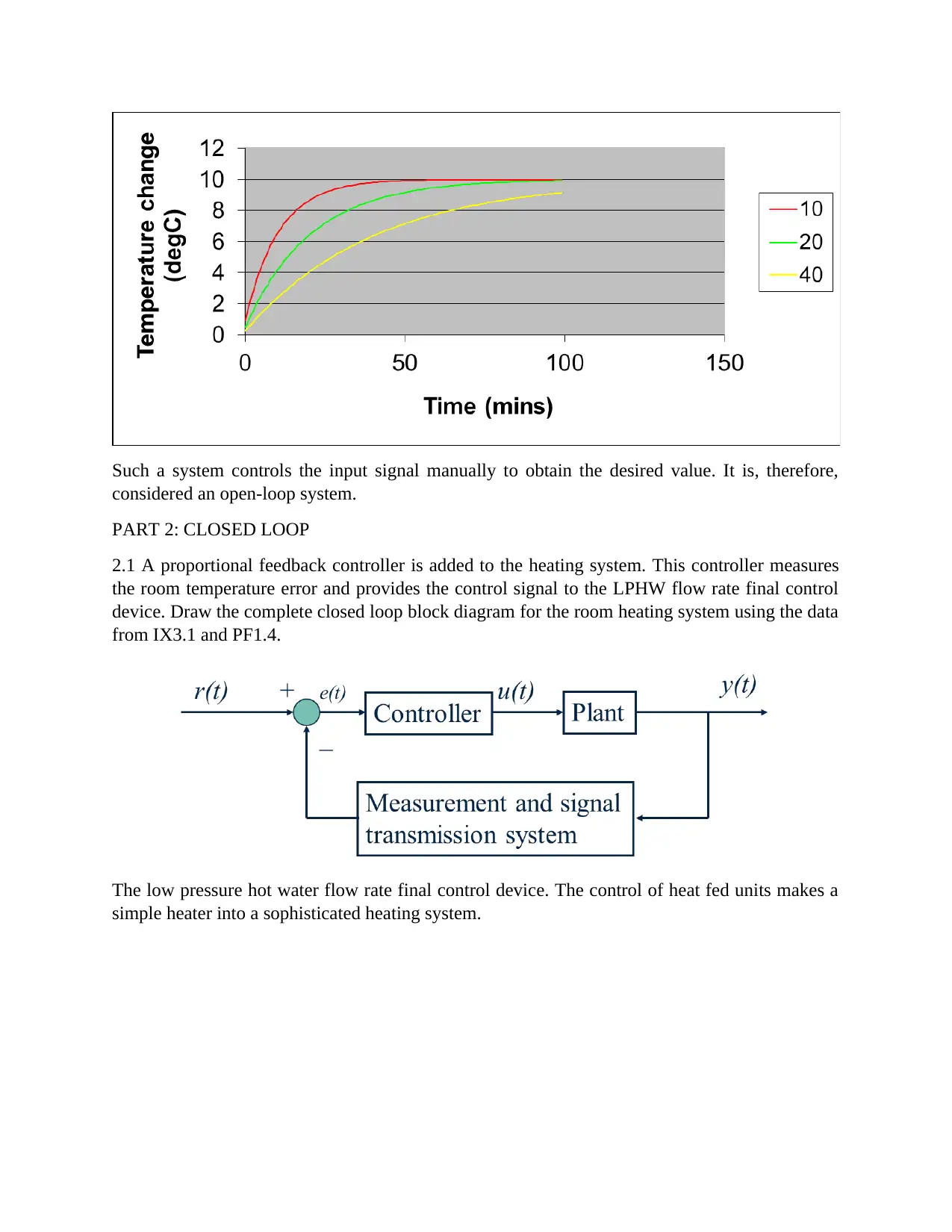
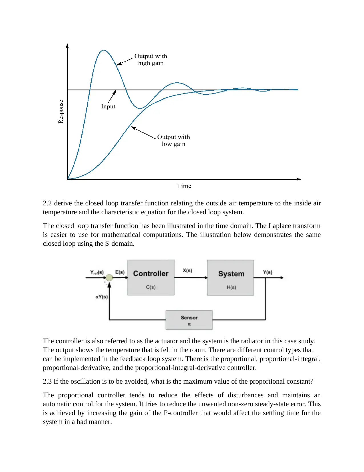
An experiment was performed for different temperatures with a step increase of 100 C with a
time constant. The time was constantly increased. The table illustrated below shows the first
order system data with the time constant as described.
Room Temperature Control System Analysis_3

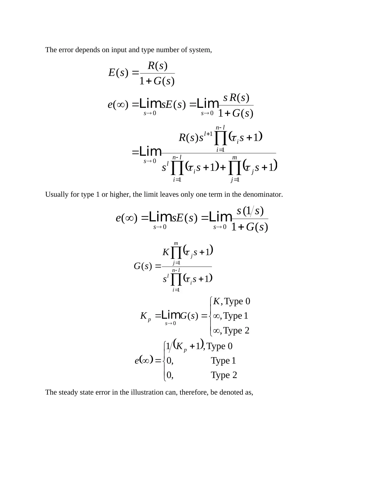
Such a system controls the input signal manually to obtain the desired value. It is, therefore,
considered an open-loop system.
PART 2: CLOSED LOOP
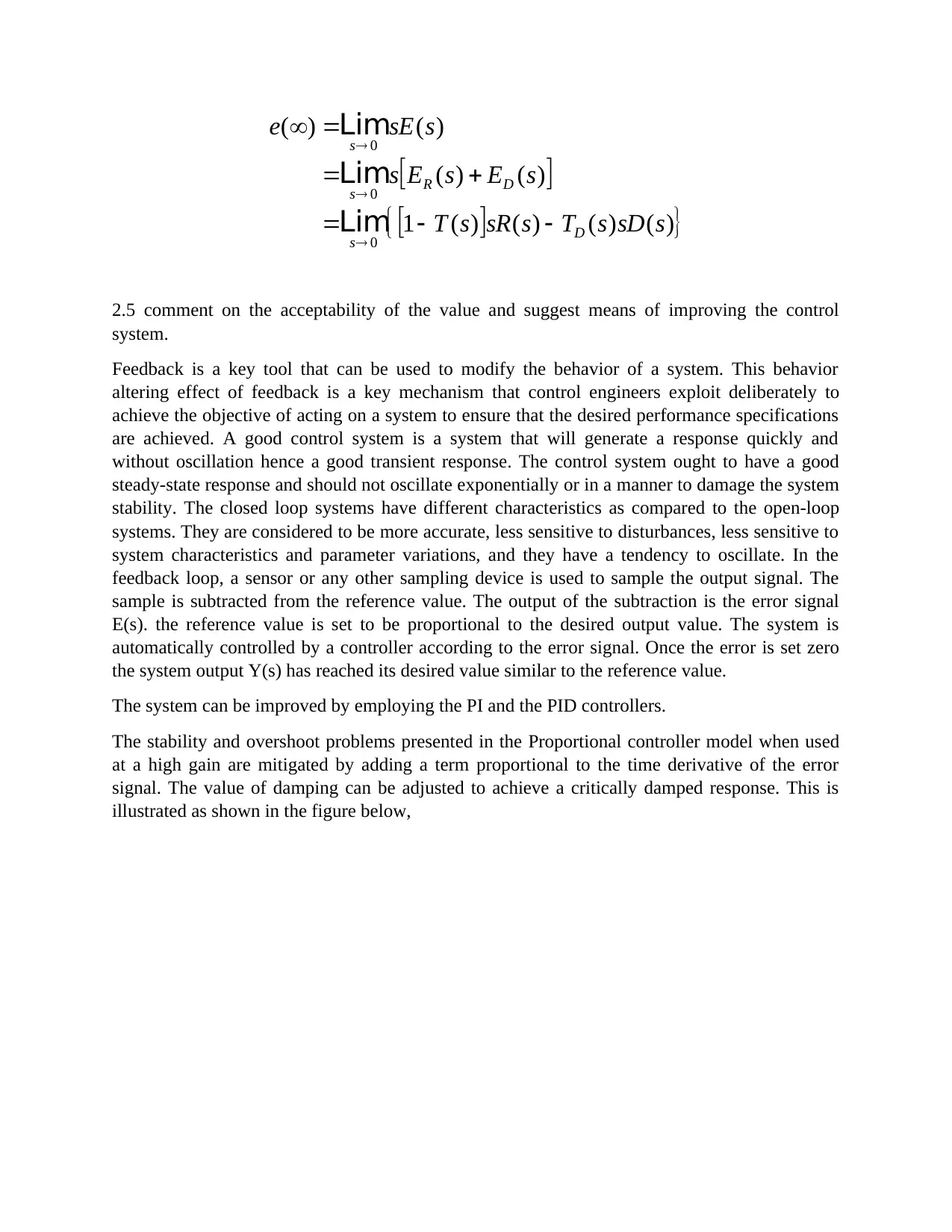
2.1 A proportional feedback controller is added to the heating system. This controller measures
the room temperature error and provides the control signal to the LPHW flow rate final control
device. Draw the complete closed loop block diagram for the room heating system using the data
from IX3.1 and PF1.4.
The low pressure hot water flow rate final control device. The control of heat fed units makes a
simple heater into a sophisticated heating system.
Room Temperature Control System Analysis_4

End of preview

Want to access all the pages? Upload your documents or become a member.

Related Documents
Building Management and Control Systems Assignment 2018/19
|11
|2174
|414

Piezoelectric Materials: Solutions to Questions
|8
|2163
|430

Continuous and Discrete Time Pid Control of DC Motor Application
|36
|6116
|114

Control and instrumentation PDF
|27
|2946
|141

Automation - Feedback Control System
|1
|8019
|192

Assignment on Dynamics and Control
|27
|2255
|13