logo

Speed Control Techniques in Brushless DC Motors Report 2022

The assignment requires explaining the different methods of controlling the speed of a DC Brushless Motor, including circuit diagrams and images from the internet. The report should be 4 pages long and should focus on 3-4 different types of speed control methods.

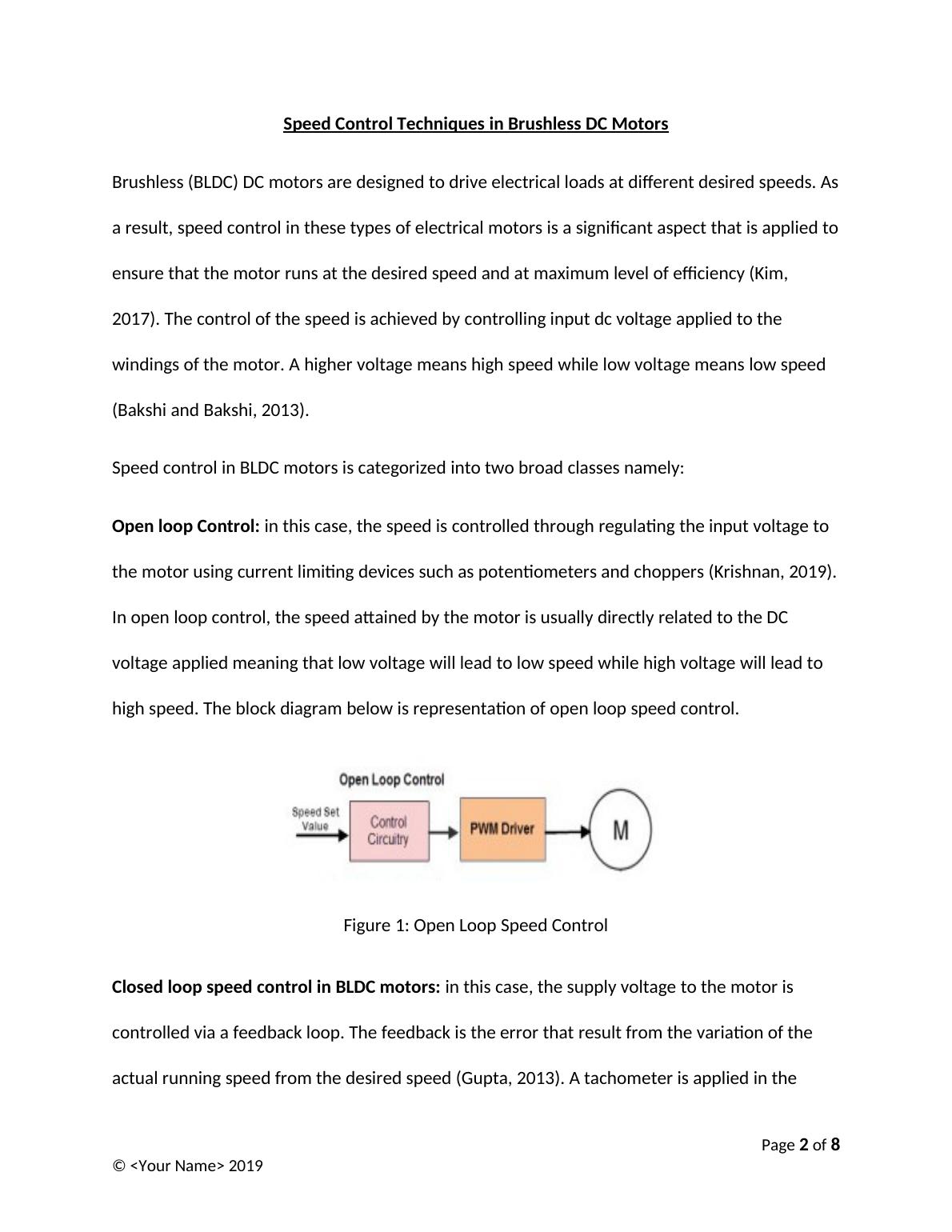
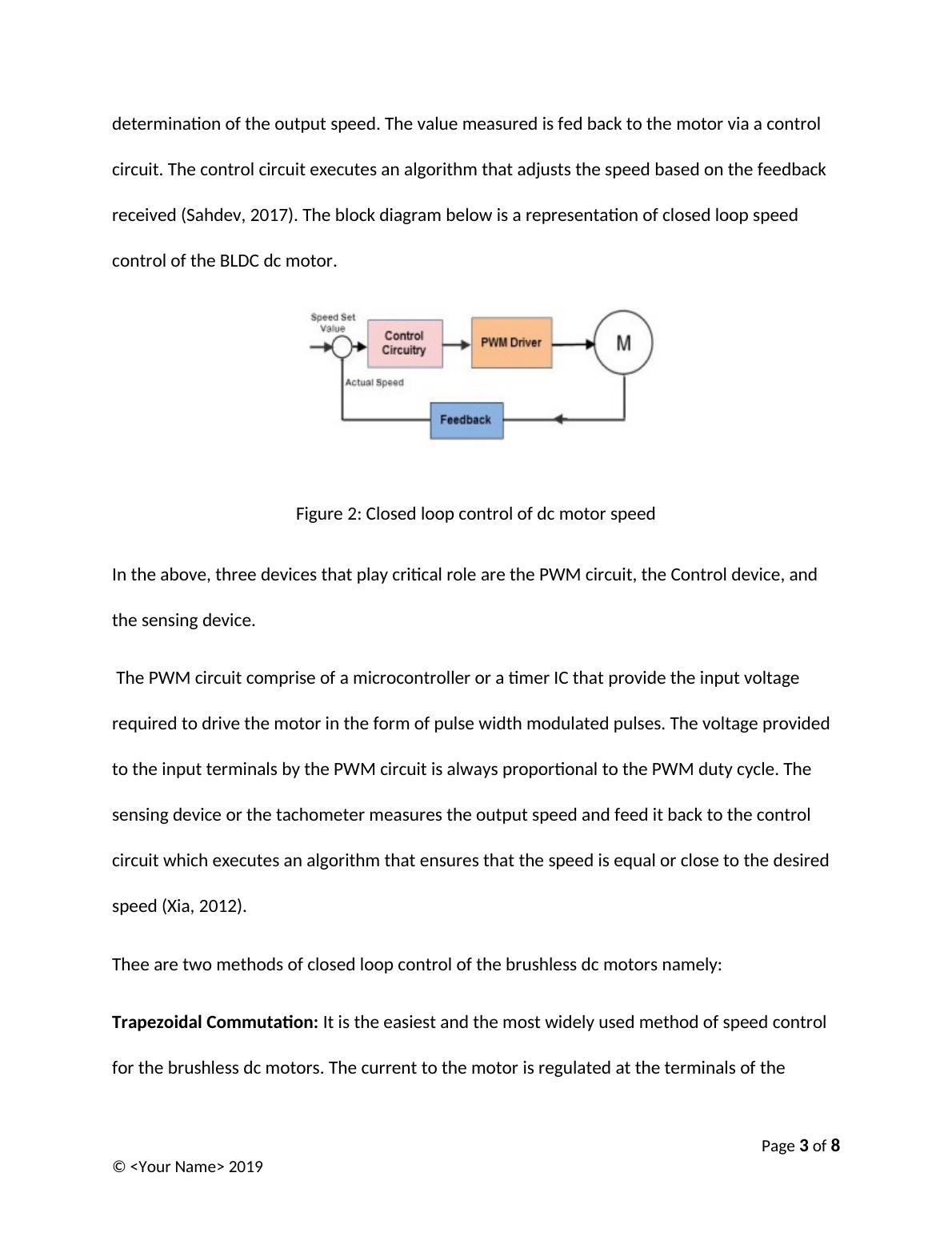
8 Pages1344 Words16 Views
   

Added on  2022-10-19

Speed Control Techniques in Brushless DC Motors Report 2022

The assignment requires explaining the different methods of controlling the speed of a DC Brushless Motor, including circuit diagrams and images from the internet. The report should be 4 pages long and should focus on 3-4 different types of speed control methods.

   Added on 2022-10-19

ShareRelated Documents
University
Speed Control Techniques in Brushless DC Motors
By
Your Name
Date
Page 1 of 8
© <Your Name> 2019
Speed Control Techniques in Brushless DC Motors Report 2022_1
Speed Control Techniques in Brushless DC Motors
Brushless (BLDC) DC motors are designed to drive electrical loads at
different desired speeds. As a result, speed control in these types of
electrical motors is a significant aspect that is applied to ensure that the
motor runs at the desired speed and at maximum level of efficiency (Kim,
2017). The control of the speed is achieved by controlling input dc voltage
applied to the windings of the motor. A higher voltage means high speed
while low voltage means low speed (Bakshi and Bakshi, 2013).
Speed control in BLDC motors is categorized into two broad classes namely:
Open loop Control: in this case, the speed is controlled through regulating
the input voltage to the motor using current limiting devices such as
potentiometers and choppers (Krishnan, 2019). In open loop control, the
speed attained by the motor is usually directly related to the DC voltage
applied meaning that low voltage will lead to low speed while high voltage
will lead to high speed. The block diagram below is representation of open
loop speed control.
Figure 1: Open Loop Speed Control
Page 2 of 8
© <Your Name> 2019
Speed Control Techniques in Brushless DC Motors Report 2022_2
Closed loop speed control in BLDC motors: in this case, the supply
voltage to the motor is controlled via a feedback loop. The feedback is the
error that result from the variation of the actual running speed from the
desired speed (Gupta, 2013). A tachometer is applied in the determination of
the output speed. The value measured is fed back to the motor via a control
circuit. The control circuit executes an algorithm that adjusts the speed
based on the feedback received (Sahdev, 2017). The block diagram below is
a representation of closed loop speed control of the BLDC dc motor.
Figure 2: Closed loop control of dc motor speed
In the above, three devices that play critical role are the PWM circuit, the
Control device, and the sensing device.
The PWM circuit comprise of a microcontroller or a timer IC that provide the
input voltage required to drive the motor in the form of pulse width
modulated pulses. The voltage provided to the input terminals by the PWM
circuit is always proportional to the PWM duty cycle. The sensing device or
the tachometer measures the output speed and feed it back to the control
circuit which executes an algorithm that ensures that the speed is equal or
close to the desired speed (Xia, 2012).
Page 3 of 8
© <Your Name> 2019
Speed Control Techniques in Brushless DC Motors Report 2022_3

End of preview

Want to access all the pages? Upload your documents or become a member.

Related Documents
Speed Control of D.C Motor
|15
|2246
|372

Competency Demonstration Report (CDR)
|8
|1614
|95

Speed Controlling Techniques of DC Motors using PWM Technique
|8
|1815
|465

Unit 45 Industrial Systems - Assignment
|9
|1741
|441

Design and Develop of Power Factor Correction Assignment
|12
|1627
|83

Buck-Boost Converter Design and Analysis
|9
|846
|75