Car Factory Pattern Creation: UML Diagram and C++ Code Analysis Report
VerifiedAdded on 2022/08/21
|8
|1233
|13
Report
AI Summary
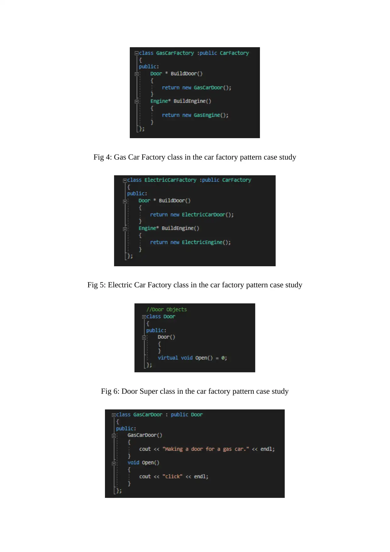
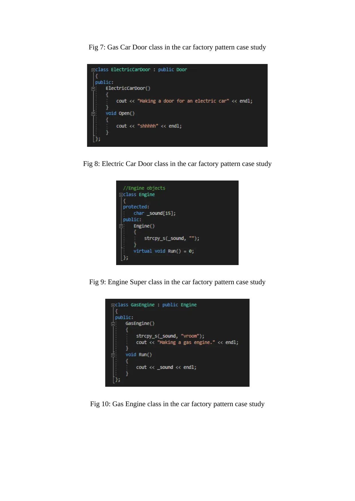
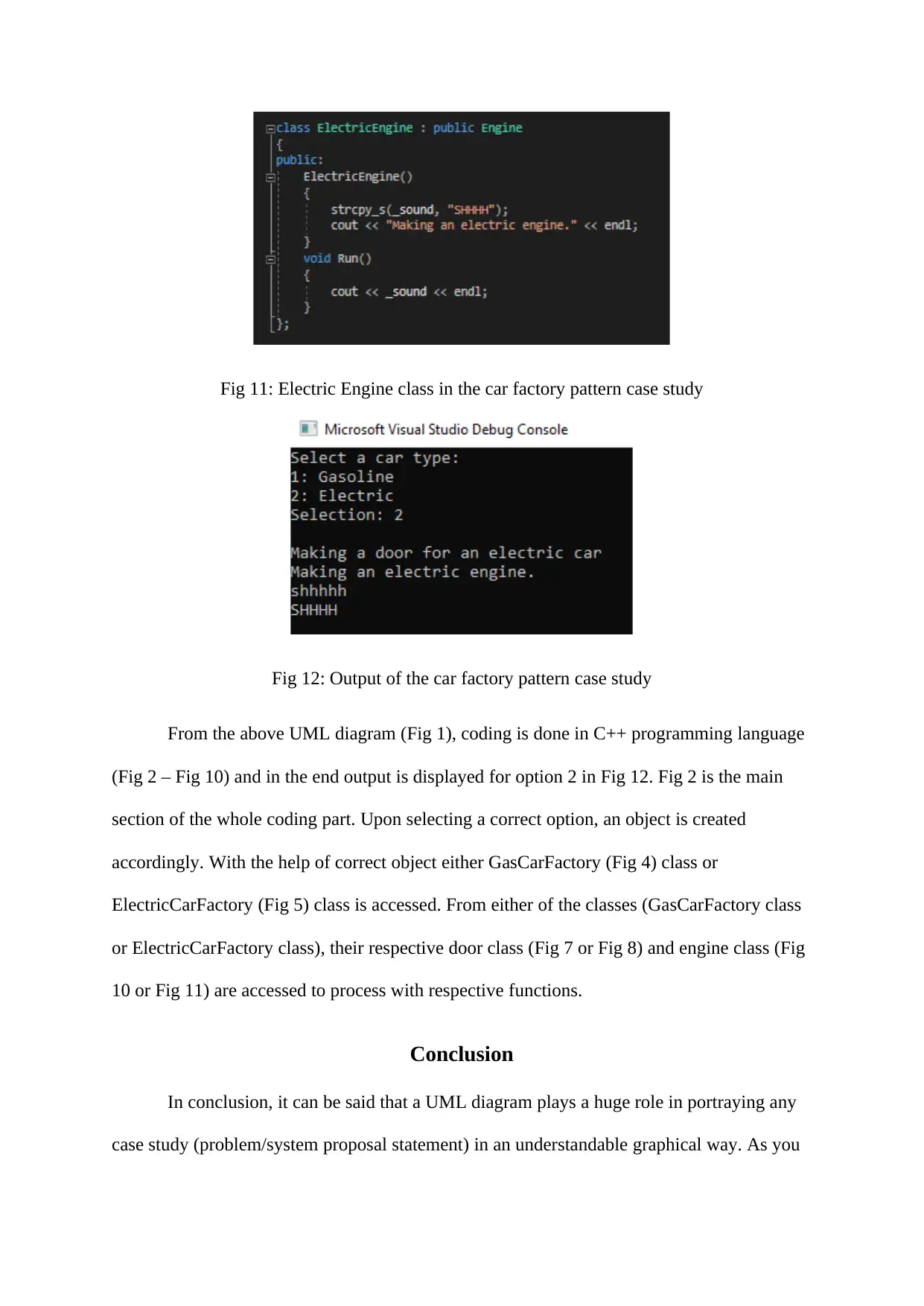
This report provides a comprehensive analysis of a car factory using UML diagrams and C++ code. It begins with an introduction to UML diagrams, their uses, and the tools available for creating them. A car factory case study is then presented, detailing the creation of a UML class diagram to represent the system's structure. The report explains the 'Forward Design' process, where the diagram precedes the code, and the 'Backward Design' approach. The diagram illustrates the interactions between different components, such as electric and gas car factories, engines, and doors. Following the diagram, the report provides C++ code implementations for the car factory pattern, including the main class, superclasses for car factories, doors, and engines, and the output. The conclusion emphasizes the importance of UML diagrams in visualizing complex systems, making them easier to understand and simulate. The report also includes references to relevant academic sources.
1 out of 8
Related Documents


Your All-in-One AI-Powered Toolkit for Academic Success.
+13062052269
info@desklib.com
Available 24*7 on WhatsApp / Email
![[object Object]](/_next/static/media/star-bottom.7253800d.svg)
Copyright © 2020–2026 A2Z Services. All Rights Reserved. Developed and managed by ZUCOL.