Communication Networks
Answering questions about Ethernet frames, bridges, and the Spanning Tree Protocol.
49 Pages5951 Words90 Views
Added on 2023-01-23
About This Document
Find solved assignments, essays, and dissertations on Communication Networks at Desklib. Get expert help for your assignments and improve your grades.
Communication Networks
Answering questions about Ethernet frames, bridges, and the Spanning Tree Protocol.
Added on 2023-01-23
ShareRelated Documents
Running head: communication networks 1
Communication Networks
[Author Name(s), First M. Last, Omit Titles and Degrees]
[Institutional Affiliation(s)]
Author Note
[Include any grant/funding information and a complete correspondence address.]
Communication Networks
[Author Name(s), First M. Last, Omit Titles and Degrees]
[Institutional Affiliation(s)]
Author Note
[Include any grant/funding information and a complete correspondence address.]
Running head: communication networks 2
Q1
a)
(i)
The CRC (Cyclic Redundancy Check) is an error detection mechanism that uses a code to check
the integrity of data frames for any errors or damages to the data that may affect integrity during
the transmission of the frame (Myoungbeom Chung, 2016).
The CRC is normally get applied on the data link layer on the Ethernet frames using the frame
check sequence number normally a 32 bit CRC is used to check whether there are errors that
might have occurred to the data or damages which might have occurred during transmission of
the data frames from the sender to the receiver.
The technique works when the result of the CRC is zero means the data frames received were
error free. The CRC is normally a remainder of the data frames which normally gets divided by
the generator polynomial. The used polynomial is normally the divisor while the data frames or
message is normally the dividend, the quotient is normally discarded, the remainder is normally
the result (Arief Wisnu Wardhana, Eka Firmansyah, & Addin Suwastono, 2016).
(ii)
Bridges have the ability to increase the throughput in an Ethernet-based network because the
bridges normally are used to join two LAN segments which may be similar or dissimilar. Like
for example, if the bridge is used two Ethernet networks, the end device on the second LAN
segment can normally communicate with the first LAN segment. The bridge can act as the traffic
Running head: communication networks 3
controller for traffic passing through it. Normally when a given packet reaches a bridge, the
bridge determines the source and destination network segment of the packet. If the bridge
determines they are on the same network segment, the bridge discards the packet while sends it if
they are on different segments. This reduces potential collisions which may occur on the
Ethernet or some damages or even wrong packets getting sent on the Ethernet. All these are
geared at increasing the speed at the Ethernet thereby increasing throughput
(iii)
A hub is a network device which is normally used to get multiple computers connected in a
network. The Hub sometimes can be used to connect with each other in an effort to increase the
total number of network and end-user devices that can be connected to the LAN network
(Fréchette, Shepherd, Thottan, & Winzer, 2013).
(iv)
The bridge is a networking device that normally works at layer 2 of the OSI model. The bridge
uses the MAC addresses to make forwarding decisions. The maintains its forwarding table which
normally consists of the MAC addresses and the port number where the address was leaned
from. When the bridge receives a packet from any of the ports, it updates the forwarding table
automatically. The bridge also makes a mapping of the MAC address of the source device to a
port that the bridge has determined the packet originated from.
Running head: communication networks 4
The following operation shall take place when the bridge is in receipt of a packet from source
MAC 4A-DE-05-26-43-81 and source port of 0/1 :
1. The forwarding table is checked for an entry for destination MAC of 98-6E-56-AB-D7-
94.
2. If there is an entry for the destination MAC in the forwarding table, then the packets get
forwarded via its corresponding port mapping. The destination device will receive the
packets
3. If the received packet is of non-IP, the bridge will broadcast the packet to every port
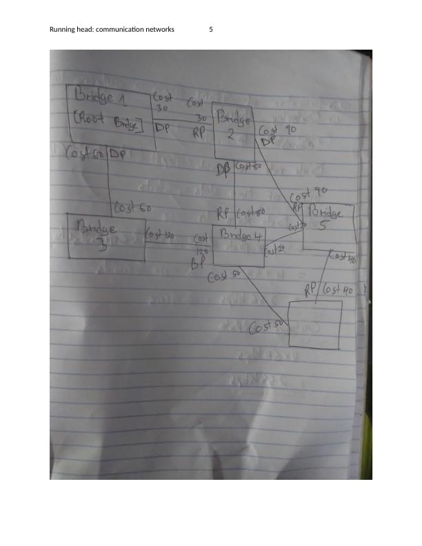
b)
c)
(i)
VLAN(Virtual Local Area Network) represent a group of computer systems, network devices,
server connected via a single LAN. The VLAN technology allows the connected systems to
communicate with one another in some form of a simulated environment as though the system is
connected over in a single LAN and as if they sharing the broadcasts domains (Wahyu Saputra &
Fajar Suryawan, 2018).
VLANs are used when the network is needed to adapt to changing network requirements,
changes to the systems and even the physical relocation of systems and servers.
The following operation shall take place when the bridge is in receipt of a packet from source
MAC 4A-DE-05-26-43-81 and source port of 0/1 :
1. The forwarding table is checked for an entry for destination MAC of 98-6E-56-AB-D7-
94.
2. If there is an entry for the destination MAC in the forwarding table, then the packets get
forwarded via its corresponding port mapping. The destination device will receive the
packets
3. If the received packet is of non-IP, the bridge will broadcast the packet to every port
b)
c)
(i)
VLAN(Virtual Local Area Network) represent a group of computer systems, network devices,
server connected via a single LAN. The VLAN technology allows the connected systems to
communicate with one another in some form of a simulated environment as though the system is
connected over in a single LAN and as if they sharing the broadcasts domains (Wahyu Saputra &
Fajar Suryawan, 2018).
VLANs are used when the network is needed to adapt to changing network requirements,
changes to the systems and even the physical relocation of systems and servers.
Running head: communication networks 5
Running head: communication networks 6
VLANs get connected via a switch to form the Ethernet network. They use the IEEE802.1Q
protocol to get the VLAN configured. In this protocol, the VLAN tag is used to identify the data
transmitted from which LAN (K. S. Kim, 2016).
The main purposed for using VLAN is to reduce data congestion and reduce latency. It also
helps improves scalability, data security and easy access to the network systems.
(ii)
The VLAN trunk is the communication link that is used by all the VLAN to communicate with
each other and other network segments. This is made possible because the trunk ports are
capable of carrying tagged data which includes the VLAN information hence won’t be discarded
by the router or the bridge. With the tagged data encapsulated include the source and destination
VLAN ids, the tagged data can be reliably be sent over the trunk link to the other VLAN
segments (Haris Diyaul Fata & Wahyu Andhyka Kusuma, 2018).
(iii)
The VLAN achieve traffic isolation via network segmentation. All device connected to the same
VLAN is under one broadcast domain. Only the particular broadcast destined for a particular
VLAN get transmitted to the VLAN thereby reducing the unnecessary traffic within the VLAN
thus improving performance and data security (Gilmer, 2009)
d)
Running head: communication networks 7
(i)
The Multi-Level Transmit 3 is a type of line coding scheme that uses 3 voltage level. The MLT-3
normally cycles through voltage levels -1,0,+1. When the scheme has to transmit a 1, the scheme
moves to the next state while if it is 0 to be transmitted, it stays in a similar state. The coding
efficiency of the MTL-3 is 1 bit/baud and one complete cycle requires 4 transmissions. The
Manchester encoding uses the synchronous clock for encoding and normally gets used at the
physical layer. The 10mbps ethernet cables use the Manchester encoding scheme since the data
bit gets encapsulated with the clock signal. This addition of the clock signal doubles the
transmission meaning the 10mbps shall become 20Mhz in terms of waveforms. Consequently,
100mbps shall be of 200Mhz wave formation. This is the main reason the Manchester coding
scheme is not used for 100mbps Ethernet (Yogeeswaran & Ramesh, 2017).
(ii)
Near End, Cross talk is signal impairments that occur where the connectors are attached to a
given twisted pair cables. The impairment does not require the two wires to be crushed together
such that the conducting metal becomes exposed. The signal interference can occur when the two
conductors are close proximity to each other such that the radiated signal from one wire can
interfere with the other signal in the other wire (Vujicic et al., 2016).
The signal echo is a phenomenon where there is the return of data sent the sending end of the
transmission or to the sending end of the transmission. They normally exist in two types, local
and remote. Echo is normally a result of the duplex operation mode of this cable made since both
the transmit and sent signal to occupy the same media. The residual signal transmitted because of
Running head: communication networks 8
trans-hybrid losses when combined with the cabling signals due to return signals are referred to
as echo (Koichi Hashimoto, Lei Hou, & Shingo Kagami, 2013)
e)
(i)
backoff value=02n −1
Where n = number of retransmissions
Hence
On 3rd retransmission,
backoff value=023 −1
0 7
Which is [0,1,2,3,4,5,6,7]
(ii) When a collision occurs, the transmission is immediately canceled, this allows reduces
transmission of packets during collisions. After the collision has occurred, the transmitter waits
again and continued the holds a random number which is double the previous one. This is
referred to as backoff exponential. The sketch below summarises the processes (Tae Min Hwang,
Seol Young Jeong, & Soon Ju Kang, 2018)
End of preview
Want to access all the pages? Upload your documents or become a member.
Related Documents
Switching Engineering: LAN Switching, Design of Switching Security, and Ethernet Switchinglg...
|19
|4666
|64
COMP609 - Networking Devices Assignmentlg...
|5
|872
|67
Device Transmission on a Network Using Token Buslg...
|4
|1329
|196
LAN Architecture for Top Network Companylg...
|11
|657
|77
Different Types of Network Cables - Cat 3, Cat 5, Cat 5e, Cat 6, Cat 6a, Cat 7lg...
|7
|1785
|126
Computer Information Systemlg...
|16
|3961
|61