Analysis and Implementation of Modulation Techniques: Communications
VerifiedAdded on 2023/04/19
|15
|3658
|114
Homework Assignment
AI Summary
This assignment provides a comprehensive overview of modulation techniques in communication systems, focusing on Amplitude Modulation (AM), Frequency Modulation (FM), and Double Sideband Suppressed Carrier (DSB-SC) modulation. It explains the principles behind each technique, detailing their mathematical representations, spectrum analysis, and implementation. The document includes code snippets for illustrating AM, FM, and DSB-SC signals, along with solutions to problems related to these modulation schemes. It discusses the advantages and disadvantages of each method, such as the bandwidth requirements and power efficiency, and highlights the applications of these modulation techniques in various communication systems. The assignment is designed to enhance understanding of signal modulation and its importance in modern communication technologies, available with other solved assignments and study resources on Desklib.

Communications Module
Assignment
Student name
Student ID Number
Date of submission
12/19/2018
Assignment
Student name
Student ID Number
Date of submission
12/19/2018
Paraphrase This Document
Need a fresh take? Get an instant paraphrase of this document with our AI Paraphraser

PART I
INTRODUCTION
A communication system carries information from one source point to a destination
through a reliable medium. There are issues that arise with the transmission of baseband signals.
The limitations of baseband transmission can be overcome using the modulation. It is the
technique in which the baseband signal is translated from lower frequency on to higher
frequency of the carrier wave. In the analogue communications, the modulation techniques are
categorized into linear and non-linear modulation schemes. The linear modulation schemes are
given as the amplitude modulation, double sideband suppressed carrier amplitude modulation,
single sideband suppressed carrier amplitude modulation, and vestigial sideband modulation. The
non-linear modulation schemes are given as frequency modulation and phase modulation.
There are three parameters in a signal that can be varied for modulation namely the
amplitude, the phase, and the frequency. Any communication system has a transmitter, receiver,
and wired or wireless channels. A communication system may seek to perform modulation to
ensure efficient transmission, multiplexing, frequency assignment, to improve signal to noise
ratio, and ease of radiation. In the modulation process, some of the signal attributes are altered to
get to that of a high frequency carrier signal which changes with the instantaneous amplitude of
the information signal. Modulation is suitable for signal transmission over long distances,
stability and noise rejection as well as the capacitive or inductive device implementation for
frequency AC input carrier to operate. Some of the common examples of modulation are the
mobile radio communications such as the cellular networks. The process of shifting the baseband
signals to the pass band range is the modulation of signals. The reverse process converts the pass
band range signals to the baseband signals by demodulation.
Amplitude modulation
The carrier signal modulates the amplitude section only. The modulating signal has an envelope
of the carrier. The total bandwidth required in the amplitude modulation is determined from the
signal. The message signal is transmitted through the carrier by adding a DC bias to the message
signal. Take the carrier signal to be cos ( 2 π f C t ) while the modulating message signal is given as,
cos ( 2 π f m t ). The AM signal is given as,
1
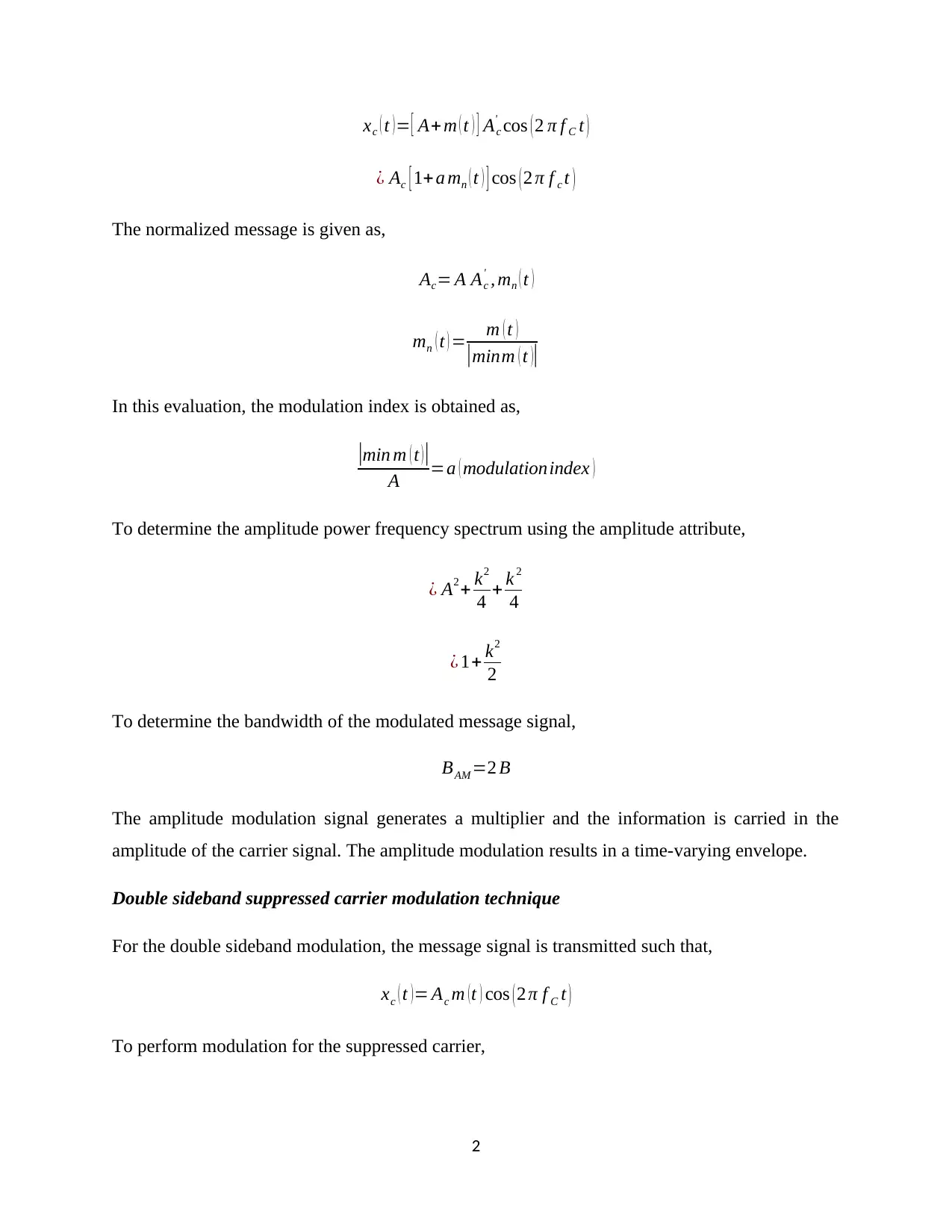
xc ( t ) = [ A+ m ( t ) ] Ac
' cos ( 2 π f C t )
¿ Ac [ 1+a mn ( t ) ] cos ( 2 π f c t )
The normalized message is given as,
Ac= A Ac
' , mn ( t )
mn ( t ) = m ( t )
|minm ( t )|
In this evaluation, the modulation index is obtained as,
|min m ( t )|
A =a ( modulationindex )
To determine the amplitude power frequency spectrum using the amplitude attribute,
¿ A2 + k2
4 + k 2
4
¿ 1+ k2
2
To determine the bandwidth of the modulated message signal,
BAM =2 B
The amplitude modulation signal generates a multiplier and the information is carried in the
amplitude of the carrier signal. The amplitude modulation results in a time-varying envelope.
Double sideband suppressed carrier modulation technique
For the double sideband modulation, the message signal is transmitted such that,
xc ( t )= Ac m (t ) cos ( 2 π f C t )
To perform modulation for the suppressed carrier,
2
⊘ This is a preview!⊘
Do you want full access?
Subscribe today to unlock all pages.

Trusted by 1+ million students worldwide
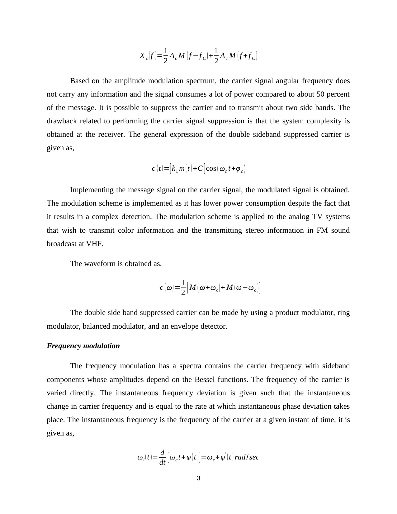
X c ( f ) = 1
2 Ac M ( f −f C ) +1
2 Ac M ( f + f C )
Based on the amplitude modulation spectrum, the carrier signal angular frequency does
not carry any information and the signal consumes a lot of power compared to about 50 percent
of the message. It is possible to suppress the carrier and to transmit about two side bands. The
drawback related to performing the carrier signal suppression is that the system complexity is
obtained at the receiver. The general expression of the double sideband suppressed carrier is
given as,
c ( t ) = [ k1 m ( t ) +C ] cos ( ωc t +φc )
Implementing the message signal on the carrier signal, the modulated signal is obtained.
The modulation scheme is implemented as it has lower power consumption despite the fact that
it results in a complex detection. The modulation scheme is applied to the analog TV systems
that wish to transmit color information and the transmitting stereo information in FM sound
broadcast at VHF.
The waveform is obtained as,
c ( ω ) =1
2 [ M ( ω+ωc ) + M ( ω−ωc ) ]
The double side band suppressed carrier can be made by using a product modulator, ring
modulator, balanced modulator, and an envelope detector.
Frequency modulation
The frequency modulation has a spectra contains the carrier frequency with sideband
components whose amplitudes depend on the Bessel functions. The frequency of the carrier is
varied directly. The instantaneous frequency deviation is given such that the instantaneous
change in carrier frequency and is equal to the rate at which instantaneous phase deviation takes
place. The instantaneous frequency is the frequency of the carrier at a given instant of time, it is
given as,
ωi ( t )= d
dt [ ωc t+φ ( t ) ]=ωc+φ' ( t ) rad /sec
3
Paraphrase This Document
Need a fresh take? Get an instant paraphrase of this document with our AI Paraphraser
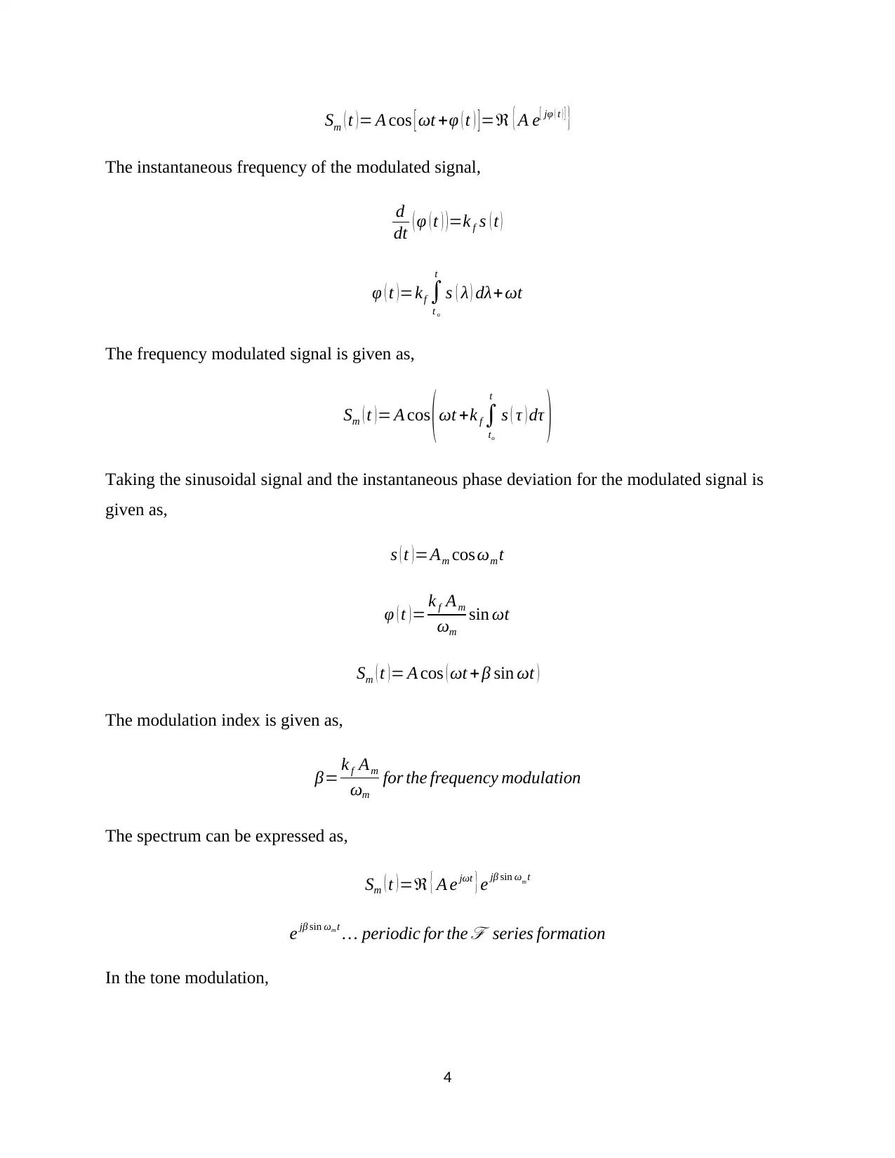
Sm ( t ) = A cos [ ωt +φ ( t ) ] =ℜ { A e[ jφ ( t ) ] }
The instantaneous frequency of the modulated signal,
d
dt ( φ ( t ) ) =k f s ( t )
φ ( t ) =kf ∫
t o
t
s ( λ ) dλ+ωt
The frequency modulated signal is given as,
Sm ( t ) = A cos ( ωt +k f ∫
to
t
s ( τ ) dτ )
Taking the sinusoidal signal and the instantaneous phase deviation for the modulated signal is
given as,
s ( t ) =Am cos ωm t
φ ( t ) = k f Am
ωm
sin ωt
Sm ( t )= A cos ( ωt + β sin ωt )
The modulation index is given as,
β= k f Am
ωm
for the frequency modulation
The spectrum can be expressed as,
Sm ( t )=ℜ { A e jωt } e jβ sin ωm t
e jβ sin ωm t … periodic for the ℱ series formation
In the tone modulation,
4
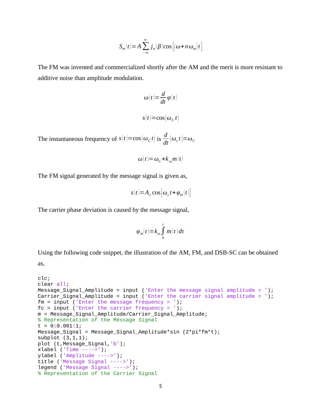
Sm ( t )= A ∑
−∞
∞
jn ( β ) cos [ (ω+n ωm ) t ]
The FM was invented and commercialized shortly after the AM and the merit is more resistant to
additive noise than amplitude modulation.
ω ( t ) = d
dt φ ( t )
s ( t )=cos ( ωC t )
The instantaneous frequency of s ( t )=cos ( ωC t ) is d
dt ( ωc t ) =ωC
ω ( t ) =ωC +k ω m ( t )
The FM signal generated by the message signal is given as,
s ( t )=Ac cos [ ωc t+ φm ( t ) ]
The carrier phase deviation is caused by the message signal,
φm ( t ) =kω∫
0
t
m ( τ ) dτ
Using the following code snippet, the illustration of the AM, FM, and DSB-SC can be obtained
as,
clc;
clear all;
Message_Signal_Amplitude = input ('Enter the message signal amplitude = ');
Carrier_Signal_Amplitude = input ('Enter the carrier signal amplitude = ');
fm = input ('Enter the message frequency = ');
fc = input ('Enter the carrier frequency = ');
m = Message_Signal_Amplitude/Carrier_Signal_Amplitude;
% Representation of the Message Signal
t = 0:0.001:1;
Message_Signal = Message_Signal_Amplitude*sin (2*pi*fm*t);
subplot (3,1,1);
plot (t,Message_Signal,'b');
xlabel ('Time ---->');
ylabel ('Amplitude ---->');
title ('Message Signal ---->');
legend ('Message Signal ---->');
% Representation of the Carrier Signal
5
⊘ This is a preview!⊘
Do you want full access?
Subscribe today to unlock all pages.

Trusted by 1+ million students worldwide
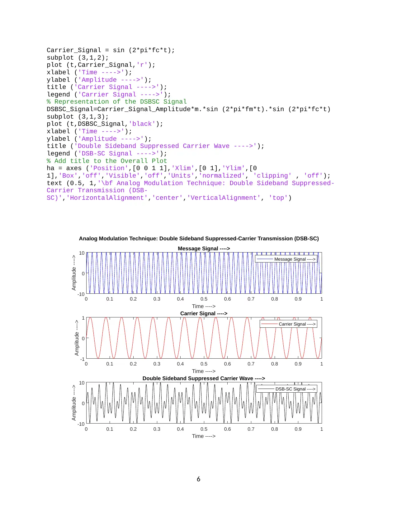
Carrier_Signal = sin (2*pi*fc*t);
subplot (3,1,2);
plot (t,Carrier_Signal,'r');
xlabel ('Time ---->');
ylabel ('Amplitude ---->');
title ('Carrier Signal ---->');
legend ('Carrier Signal ---->');
% Representation of the DSBSC Signal
DSBSC_Signal=Carrier_Signal_Amplitude*m.*sin (2*pi*fm*t).*sin (2*pi*fc*t)
subplot (3,1,3);
plot (t,DSBSC_Signal,'black');
xlabel ('Time ---->');
ylabel ('Amplitude ---->');
title ('Double Sideband Suppressed Carrier Wave ---->');
legend ('DSB-SC Signal ---->');
% Add title to the Overall Plot
ha = axes ('Position',[0 0 1 1],'Xlim',[0 1],'Ylim',[0
1],'Box','off','Visible','off','Units','normalized', 'clipping' , 'off');
text (0.5, 1,'\bf Analog Modulation Technique: Double Sideband Suppressed-
Carrier Transmission (DSB-
SC)','HorizontalAlignment','center','VerticalAlignment', 'top')
0 0.1 0.2 0.3 0.4 0.5 0.6 0.7 0.8 0.9 1
Time ---->
-10
0
10
Amplitude ----> Message Signal ---->
Message Signal ---->
0 0.1 0.2 0.3 0.4 0.5 0.6 0.7 0.8 0.9 1
Time ---->
-1
0
1
Amplitude ----> Carrier Signal ---->
Carrier Signal ---->
0 0.1 0.2 0.3 0.4 0.5 0.6 0.7 0.8 0.9 1
Time ---->
-10
0
10
Amplitude ----> Double Sideband Suppressed Carrier Wave ---->
DSB-SC Signal ---->
Analog Modulation Technique: Double Sideband Suppressed-Carrier Transmission (DSB-SC)
6
Paraphrase This Document
Need a fresh take? Get an instant paraphrase of this document with our AI Paraphraser
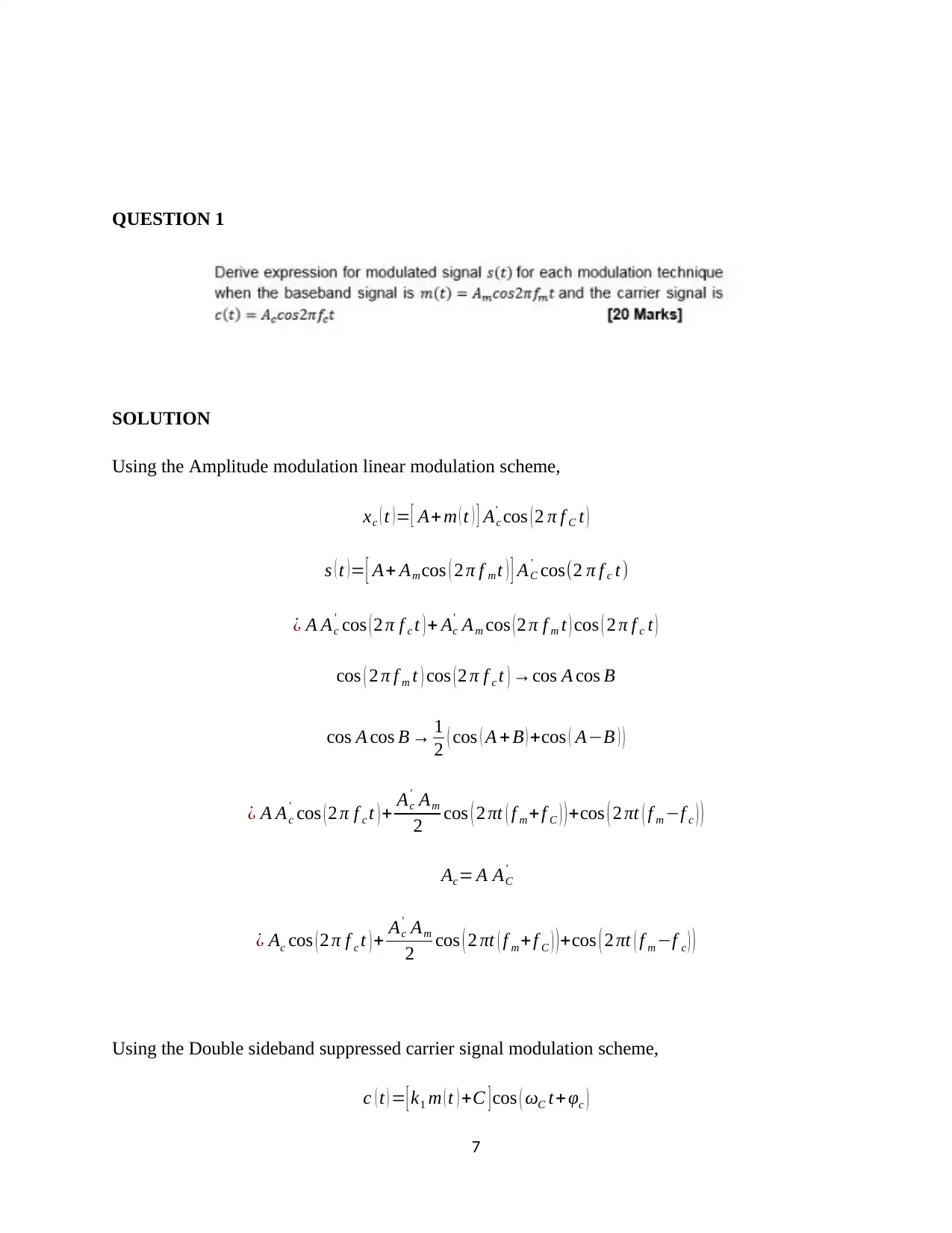
QUESTION 1
SOLUTION
Using the Amplitude modulation linear modulation scheme,
xc ( t )= [ A+ m ( t ) ] Ac
' cos ( 2 π f C t )
s ( t )= [ A+ Am cos ( 2 π f mt ) ] AC
' cos(2 π f c t)
¿ A Ac
' cos ( 2 π f c t ) + Ac
' Am cos ( 2 π f m t ) cos ( 2 π f c t )
cos ( 2 π f m t ) cos ( 2 π f c t ) →cos A cos B
cos A cos B → 1
2 ( cos ( A + B ) +cos ( A−B ) )
¿ A Ac
' cos ( 2 π f c t ) + Ac
' Am
2 cos ( 2 πt ( f m +f C ) ) +cos ( 2 πt ( f m −f c ) )
Ac= A AC
'
¿ Ac cos ( 2 π f c t ) + Ac
' Am
2 cos ( 2 πt ( f m +f C ) ) +cos ( 2 πt ( f m −f c ) )
Using the Double sideband suppressed carrier signal modulation scheme,
c ( t ) = [ k1 m ( t ) +C ] cos ( ωC t+ φc )
7
The message signal is passed as,
m ( t ) =Am cos ( 2 π f m t )
c ( t ) = [ k1 Am cos ( 2 π f m t ) +C ] cos ( ωC t+φc )
c ( t ) =k1 Am cos(2 π f m t) cos ( ωC t +φc ) + C cos ( ωC t +φc )
cos A cos B → 1
2 ( cos ( A + B ) +cos ( A−B ) )
cos ( 2 π f m t ) cos ( ωC t +φc ) → 1
2 ( cos ( 2 π f m t+2 π f c t +φc ) + cos ( 2 π f m t−2 π f c t−φc ) )
c ( t ) =[ k1 Am
2 ( cos ( 2 π f m t +2 π f c t +φc ) + cos ( 2 π f mt −2 π f c t−φc ) )+C cos ( ωC t +φc ) ]
When the value of C=0, the double sideband modulator is balanced such that,
c ( t ) =[ k1 Am
2 ( cos ( 2 π f m t +2 π f c t +φc ) + cos ( 2 π f mt −2 π f c t−φc ) ) ]
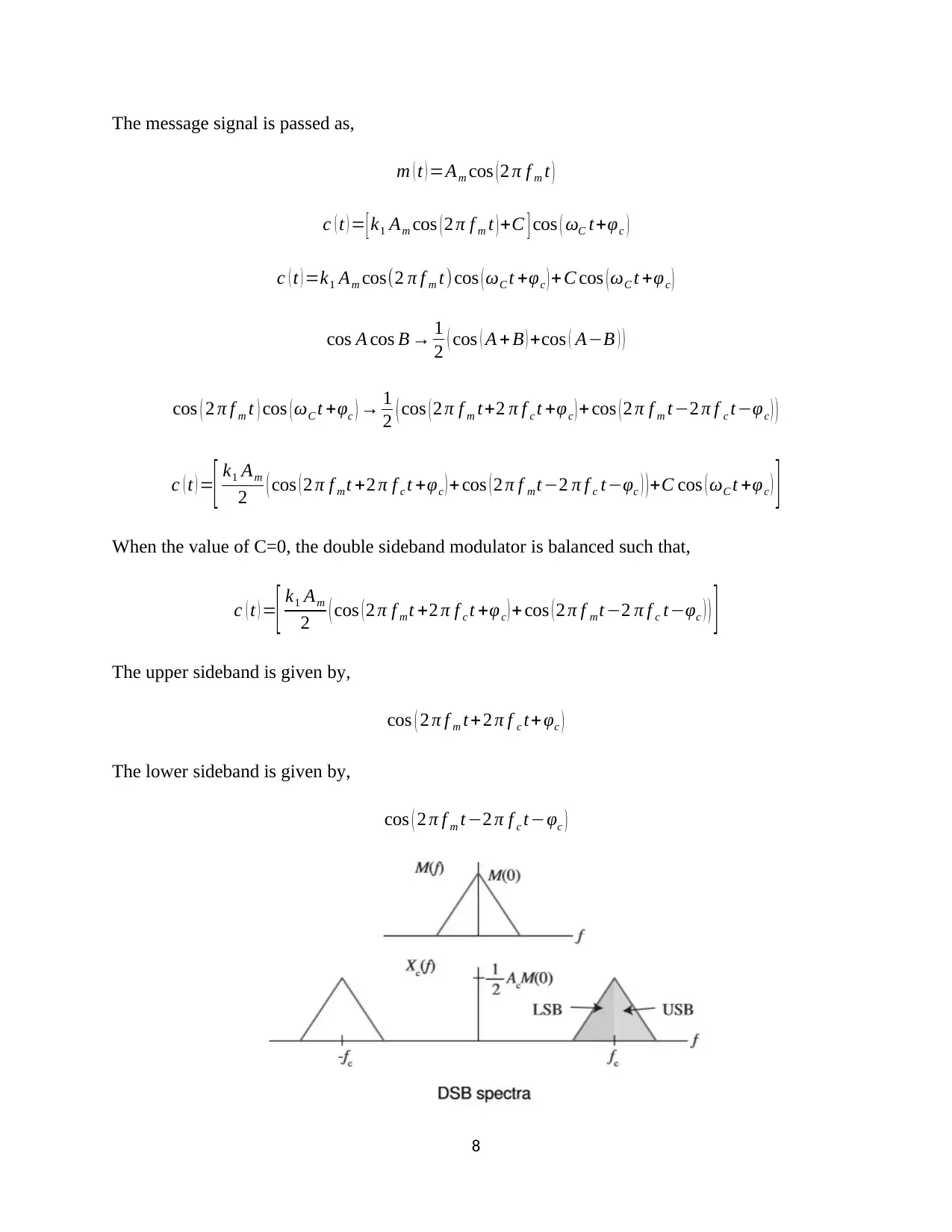
The upper sideband is given by,
cos ( 2 π f m t+ 2 π f c t+ φc )
The lower sideband is given by,
cos ( 2 π f m t−2 π f c t−φc )
8
⊘ This is a preview!⊘
Do you want full access?
Subscribe today to unlock all pages.

Trusted by 1+ million students worldwide
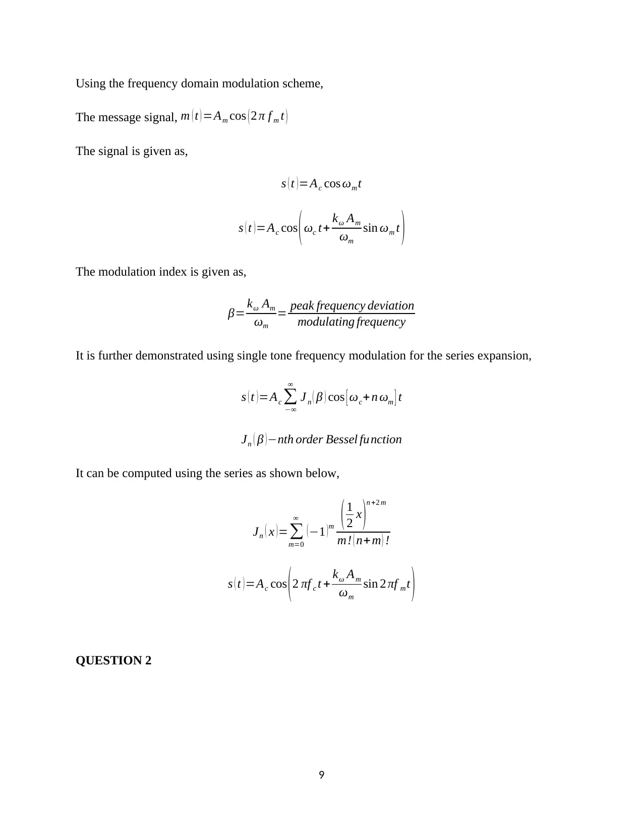
Using the frequency domain modulation scheme,
The message signal, m ( t ) =Am cos ( 2 π f m t )
The signal is given as,
s ( t ) =Ac cos ωm t
s ( t )=Ac cos (ωc t+ kω Am
ωm
sin ωm t )
The modulation index is given as,
β= kω Am
ωm
= peak frequency deviation
modulating frequency
It is further demonstrated using single tone frequency modulation for the series expansion,
s ( t ) =Ac ∑
−∞
∞
J n ( β ) cos [ ωc+ n ωm ] t
Jn ( β ) −nth order Bessel function
It can be computed using the series as shown below,
Jn ( x ) =∑
m=0
∞
( −1 ) m ( 1
2 x )
n +2 m
m! ( n+ m ) !
s ( t )=Ac cos (2 πf c t + kω Am
ωm
sin 2 πf m t )
QUESTION 2
9
Paraphrase This Document
Need a fresh take? Get an instant paraphrase of this document with our AI Paraphraser
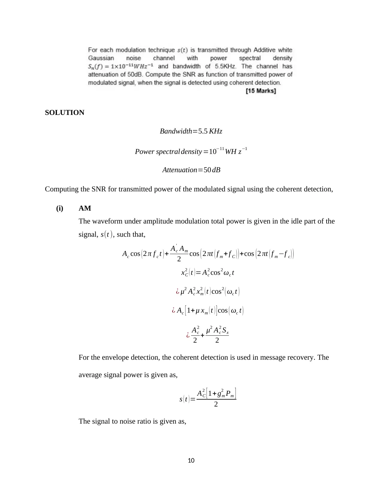
SOLUTION
Bandwidth=5.5 KHz
Power spectraldensity =10−11 WH z−1
Attenuation=50 dB
Computing the SNR for transmitted power of the modulated signal using the coherent detection,
(i) AM
The waveform under amplitude modulation total power is given in the idle part of the
signal, s(t ), such that,
Ac cos ( 2 π f c t ) + Ac
' Am
2 cos ( 2 πt ( f m + f C ) ) +cos ( 2 πt ( f m −f c ) )
xC
2 ( t ) = Ac
2 cos2 ωc t
¿ μ2 Ac
2 xm
2 ( t ) cos2 ( ωc t )
¿ Ac [ 1+ μ xm ( t ) ] cos ( ωc t )
¿ Ac
2
2 + μ2 Ac
2 Sx
2
For the envelope detection, the coherent detection is used in message recovery. The
average signal power is given as,
s ( t )= AC
2 [ 1+gm
2 Pm ]
2
The signal to noise ratio is given as,
10
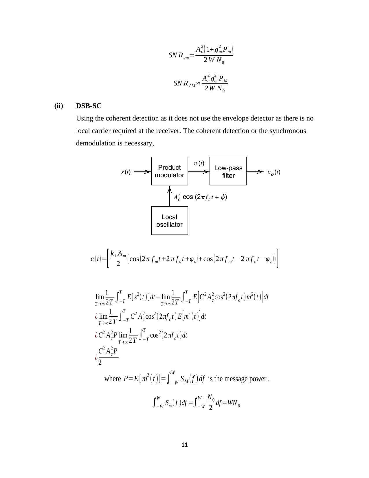
SN Ram= Ac
2 ( 1+ gm
2 Pm )
2 W N0
SN R AM ≈ Ac
2 gm
2 PM
2W N0
(ii) DSB-SC
Using the coherent detection as it does not use the envelope detector as there is no
local carrier required at the receiver. The coherent detection or the synchronous
demodulation is necessary,
c ( t ) =[ k1 Am
2 ( cos ( 2 π f m t +2 π f c t +φc ) + cos ( 2 π f mt −2 π f c t−φc ) ) ]
11
lim
T →∞
1
2T ∫−T
T
E[ s2(t )]dt = lim
T →∞
1
2T ∫−T
T
E [ C2 Ac
2 cos2(2 πf c t )m2(t ) ] dt
¿ lim
T →∞
1
2 T ∫−T
T
C2 Ac
2 cos2 (2 πf c t ) E [ m2 (t ) ] dt
¿ C2 Ac
2 P lim
T →∞
1
2 T ∫−T
T
cos2(2 πf c t )dt
¿ C2 Ac
2 P
2
where P=E [ m2 (t )]=∫−W
W
SM (f )df is the message power .
∫−W
W
Sw( f )df =∫−W
W N0
2 df =WN 0
⊘ This is a preview!⊘
Do you want full access?
Subscribe today to unlock all pages.

Trusted by 1+ million students worldwide
1 out of 15
Related Documents
Your All-in-One AI-Powered Toolkit for Academic Success.
+13062052269
info@desklib.com
Available 24*7 on WhatsApp / Email
![[object Object]](/_next/static/media/star-bottom.7253800d.svg)
Unlock your academic potential
Copyright © 2020–2026 A2Z Services. All Rights Reserved. Developed and managed by ZUCOL.


