RFID Antenna Design: CE3 Report on Impedance Matching and Simulation
VerifiedAdded on 2020/02/24
|8
|1715
|107
Report
AI Summary
This report presents the design and implementation of an RFID tag antenna, focusing on impedance matching between the antenna and the RFID chip to optimize performance and wireless communication. The project involved understanding the theory of RFID technology, including backscattering processes, and the application of engineering knowledge to enhance the antenna's detection range. The report details the objectives, methodology, and challenges faced during the project, such as determining the reflection coefficient and matching impedance using the Smith Chart. The author fabricated the antenna, conducted simulations using HFSS software, and analyzed the results to achieve the desired antenna gain and impedance matching. The report concludes with a review of the project's outcomes, highlighting the author's contributions as a team leader and the successful implementation of the antenna design, resulting in improved performance and a deeper understanding of RFID technology. The design focused on achieving optimal impedance matching between the RFID tag and the antenna, crucial for efficient wireless communication and maximizing the antenna's read range.

Competency
Demonstration Report
(CDR)
Career Episode 3
Sainath Punukollu
Demonstration Report
(CDR)
Career Episode 3
Sainath Punukollu
Paraphrase This Document
Need a fresh take? Get an instant paraphrase of this document with our AI Paraphraser

CE 3.1: Project Introduction
Name of the Project : Designing of RFID Tag Antenna matched to Micro Chip
Geographical Location : [Please Fill]
Project Duration : [Please Fill]
Organization : [Please Fill]
Position in the Project : Team Leader
CE 3.2. Project Background
CE 3.2.1: Characteristics of the Project
The applications of RFID technology are widely used in the wireless devices for
collecting and transmitting the information from one point to another through wireless medium.
I have observed that in the existing antennas, the vendors provided values of impedance of the
RFID chip at three different frequencies. I have took this project to implement and propose a
design of antenna with the application of RFID technology. This has allowed in implementing
the wireless communication between different antennas. I have observed that the difference in
the impedance level of the RFID tag and the antenna determined and impacts the efficiency and
performance of the antenna. In this project I have proposed an advanced design of the antenna
that allowed the proper measurement and matching of the impedance of the RFID chip and the
antenna for ensuring the proper quality and performance of the tag antenna.
Page 1 of 8

CE 3.2.2: Objectives developed for project
I have determined that proper communication between the RFID tags are conducted with
the application of backscattering process. Therefore, in this project, I have aimed at transmitting
the energy and data from the RFID tags used in the antenna design by identification and
backscattering theory. For the successful completion of the project, I have considered the
significant aim of integrating the RFID tag along with the design of the antenna. In addition to
that, I have developed various objectives as illustrated in the section below:
To determine the non-linear load of the antenna;
To demonstrate the impact of impedance variance over the antenna performance;
To match the impedance of both the RFID tag and the antenna;
To implement the backscattering process for passive communication;
To fabricate the design of the proposed antenna;
To simulate the antenna using HFSS software;
CE 3.2.3: My area of work
I have considered the project for the establishment and performance simulation of the
RFID antenna. I have identified characteristics of the antenna design and demonstrated the
utilization of the RFID tag in determining wireless communication. I have studied past studies
and articles based on the RFID antenna design and identified the proper characteristics and the
operational factors for the antenna. I have further, determined the technical properties and
implementation work required for developing the appropriate design of the RFID tag antenna.
Page 2 of 8
⊘ This is a preview!⊘
Do you want full access?
Subscribe today to unlock all pages.

Trusted by 1+ million students worldwide

CE 3.2.4: Project Group
Figure 1: Team Member Associated with the Project
CE 3.2.5: My responsibilities throughout the project
In this project, I have provided with the major responsibility of managing and controlling
the progress antenna design project. I have fabricated the design and printed the required antenna
for further simulation. I have carried out the process and technique for matching the impedance
of the tag and the antenna proposed in this project. In addition to that, I have the responsibility of
guiding the team members with the proper information and technical knowledge for successfully
completing the project.
Page 3 of 8
Paraphrase This Document
Need a fresh take? Get an instant paraphrase of this document with our AI Paraphraser
CE 3.3: Distinctive Activity
CE 3.3.1: Comprehending the Theory of the project
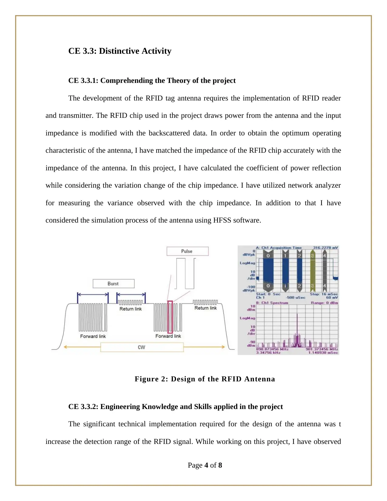
The development of the RFID tag antenna requires the implementation of RFID reader
and transmitter. The RFID chip used in the project draws power from the antenna and the input
impedance is modified with the backscattered data. In order to obtain the optimum operating
characteristic of the antenna, I have matched the impedance of the RFID chip accurately with the
impedance of the antenna. In this project, I have calculated the coefficient of power reflection
while considering the variation change of the chip impedance. I have utilized network analyzer
for measuring the variance observed with the chip impedance. In addition to that I have
considered the simulation process of the antenna using HFSS software.
Figure 2: Design of the RFID Antenna
CE 3.3.2: Engineering Knowledge and Skills applied in the project
The significant technical implementation required for the design of the antenna was t
increase the detection range of the RFID signal. While working on this project, I have observed
Page 4 of 8

that the gain of the antenna with RFID tag requires a small dipole antenna that provides
minimum flexibility to improve the omni-directional property. I have used one receiving antenna
and one transmitting antenna for establishing the RF communication over the antenna. I have
obtained the power density of the antenna from the distance of R1. For the calculation I have
determined the distance as (θtrans, φtrans) and utilized the following formulae:
W trans = [P tras G trans (θtrans, φtrans)] / 4 πR1
In the above equation, I have used P tras as for denoting the transmitting antenna’s input
power and G trans as the reader antenna’s gain. I have further used the product of gain and input
power for determining the obtained isotropic radiated power of the proposed RDIF antenna.
While designing the RFID antenna, I have ensured that the minimum power is being consumed
by the antenna while providing the operation at maximum of R distance from the tag microchip.
CE 3.3.3: Accomplishment and Task Performed
I have attached an RFID tag directly to the micro chip antenna for establishing wireless
communication. Throughout the design and fabrication of the antenna, I have ensured that the
matching of impedance between the chip and the antenna is essential for the project. I have
observed that the impedance of the RFID antenna significantly impacts the characteristics and
performance of the antenna within a wide range tag. I have fabricated the proposed design o f the
antenna and conducted the simulation process.
CE 3.3.4: Identified Issues and Their Solutions
Issue: I have focused on improving the performance of the antenna with the modification
of different parameter of the antenna design. I have studied various papers and articles and
observed that the modification to the reflection coefficient is required to achieve appropriate and
Page 5 of 8
⊘ This is a preview!⊘
Do you want full access?
Subscribe today to unlock all pages.

Trusted by 1+ million students worldwide

enhanced quality in the antenna design. In this project I have tried to keep the coefficient of
power reflection lesser than one. I haves faced significant issue in the project while determining
the reflection coefficient for the proposed RFID antenna.
Solution: I order to obtain the appropriate value of the antenna design; I have utilized the
Smith Chart graphical approach for calculation. I have utilized the concept of thumb rule for
matching the power transfer with the conjugate matching. Through this I was able to keep the
input impedance of the antenna having the same value as the chip impedance of the complex
conjugate. In addition to that, I have used polynomial interpolation for the process of
extrapolation. From the analysis I have observed that for each frequency, the chip resistances of
extrapolation are observed below zero.
CE 3.3.5: Plan for producing creative and innovative work
I have designed the antenna and fabricated the proposed structure for analysis. I have
printed the antenna on dipole structure of T-matched fold. For the simulation process, I have
conducted the analysis and simulation with commercial simulation HFSS software package.
During the simulation process, I have plotted the impedance graph along the side of the
conjugated chip. I have utilized the constant chip values for calculating the power reflection
coefficient. In order to evaluate the performance of tag RDID antenna, I have conducted the
simulation with anechoic chamber. While performing the simulation, ii have observed that the
RFID chip was operating at 11 dbm of maximum power.
CE 3.3.6: Collaborative work
I have identified that the development of the RFID tag antenna was a multidimensional
task. I have evaluated and identified the various technical module and implementation criteria
Page 6 of 8
Paraphrase This Document
Need a fresh take? Get an instant paraphrase of this document with our AI Paraphraser

that has required to be implemented in this project. I have further allocated the work load among
the team members for ensuring the proper flow of work and continuous progress.
CE 3.4: Project Review
CE 3.4.1: Project Overview
Overview: For the design of the RFID tag antenna, I have ensured the application of read
range parameter while developing the design of the antenna. With the application of
backscattering theory, I was successful in deriving all the required and appropriate equation for
determining the optimum geometry of the antenna. Furthermore, in the proposed design of the
antenna, I was able to obtain the equal impedance for both the antenna and the RFID tag.
Therefore, this allowed in developing an advanced design for the RFID tag antenna.
Output: I have operated the designed chip at the maximum read range of 11 bdm. During
the input of 866.5 MHz input impedance I have observed high output frequency matching the
953 MHz. Apart from that, from the analysis I have determined that the 8 ohms of resistance has
given best fit for the 2 dBi of antenna gain.
CE 3.4.2: My contribution to work
I have worked for the design and fabrication of the RFID tag antenna as a team leader. I
have demonstrated the work to the team members working alongside. In addition to that, I have
identified the different functional element that were necessary for the design of the antenna and
distributed the task among the team members. Apart from that, I have assisted and guided the
team members associated in this project for the proper implementation and fabrication of the
antenna design with the integration of the RFID tag.
Page 7 of 8
1 out of 8
Related Documents
Your All-in-One AI-Powered Toolkit for Academic Success.
+13062052269
info@desklib.com
Available 24*7 on WhatsApp / Email
![[object Object]](/_next/static/media/star-bottom.7253800d.svg)
Unlock your academic potential
Copyright © 2020–2026 A2Z Services. All Rights Reserved. Developed and managed by ZUCOL.


