Computer Systems Architecture and Operating Systems - BTEC HND Report
VerifiedAdded on 2023/03/24
|23
|1375
|93
Report
AI Summary
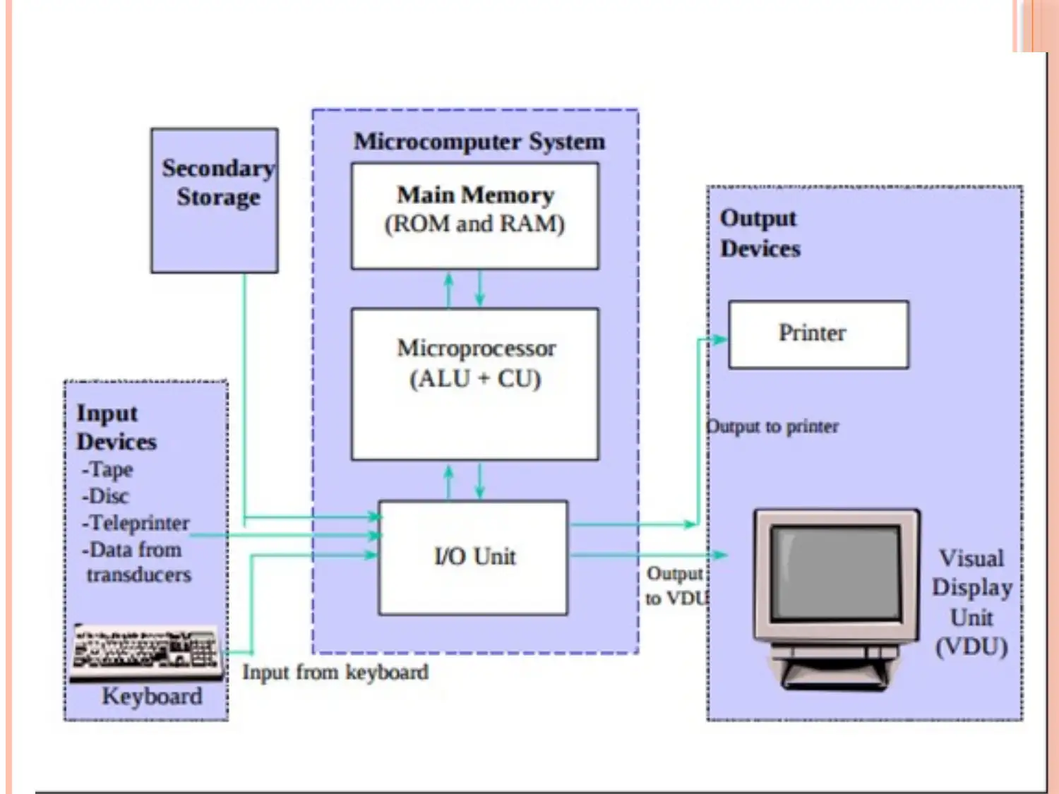
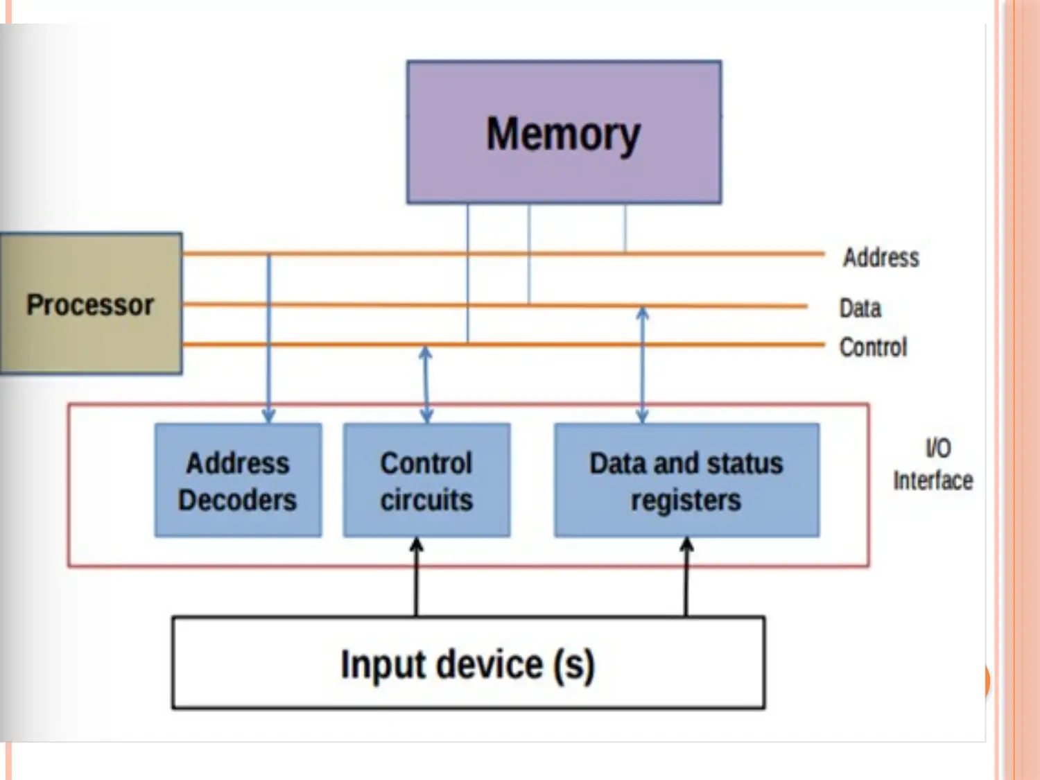
This report provides a detailed overview of computer systems architecture, covering the main subsystems such as the Central Processing Unit (CPU), storage unit, and I/O devices, as well as their organization and connections. It explains the purpose and operation of the CPU, including its components like the Arithmetic Logic Unit (ALU), Control Unit (CU), and registers, and discusses factors affecting CPU performance. The report also explores different types of operating systems, including real-time, single-user multi-tasking, and multi-user systems, highlighting key architectural features such as hardware, kernel, shell, and utilities. Furthermore, it outlines the services provided by an operating system, including program execution, I/O operations, file system manipulation, communication, error detection, resource allocation, and protection mechanisms. The document concludes with a list of references used in compiling the report.

1 out of 23
Related Documents


Your All-in-One AI-Powered Toolkit for Academic Success.
+13062052269
info@desklib.com
Available 24*7 on WhatsApp / Email
![[object Object]](/_next/static/media/star-bottom.7253800d.svg)
Copyright © 2020–2026 A2Z Services. All Rights Reserved. Developed and managed by ZUCOL.