Detailed Report on Computer Systems Architecture: Data and Operations
VerifiedAdded on 2024/04/24
|36
|5862
|476
Report
AI Summary
This report provides a comprehensive overview of computer systems architecture, focusing on how data is represented and processed within computer systems. It begins by explaining how numeric and alphanumeric data are coded, including examples of integers, floating points, octal, and hexadecimal systems. The report details the conversion of different data types like images, audios, and videos into binary format for storage. It illustrates the key computer system components, such as the CPU, memory, and peripherals, and their interactions based on the Von-Neumann architecture. The different types of memory, including SRAM, DRAM, ROM, Flash memory, and Cache memory, are explained. Furthermore, the report compares RISC and CISC chips, elaborates on the use of processor registers in the fetch-execute cycle, and discusses communication methods like polling and interrupts. The document is a student contribution available on Desklib, a platform offering AI-based study tools and solved assignments.
Computer Systems
Architecture
0
Architecture
0
Paraphrase This Document
Need a fresh take? Get an instant paraphrase of this document with our AI Paraphraser
Contents
Introduction......................................................................................................................................4
LO1 Understand how data can be represented within computer systems.......................................5
P1. Explain using examples how numeric and alphanumeric data can be coded within a
computer system..........................................................................................................................5
P2. Explain using examples how different types of data can be converted and stored in
computer system..........................................................................................................................7
P3. Convert numeric data between different number systems including floating point..............9
LO2 Understand the functions of computer system components..................................................18
P5. Illustrate the key computer system components and how they interact..............................18
P6. Explain the different types of memory that can be attached to a processor........................21
P7. Explain how polling and interrupts are used to allow communication between processor
and peripherals...........................................................................................................................24
LO3 Understand the principles of processor operations................................................................25
P8. Compare Reduced Instruction Set Computer (RISC) chips and Complex Instruction Set
Computer (CISC) chips .............................................................................................................26
P9. Illustrate the use of the different processor registers in the fetch-execute cycle.................29
Conclusion.....................................................................................................................................32
References......................................................................................................................................33
1
List of Figures
Figure 1- Image representation........................................................................................................7
Figure 2- OR Gate.........................................................................................................................12
Figure 3- AND Gate......................................................................................................................12
Figure 4- NOT Gate.......................................................................................................................13
Figure 5- NAND Gate...................................................................................................................13
Figure 6- NOR Gate.......................................................................................................................14
Figure 7- XOR Gate.......................................................................................................................15
Figure 8- Combined Circuit...........................................................................................................15
Figure 9- Von-Neumann architecture............................................................................................18
Figure 10- Scanner.........................................................................................................................18
Figure 11- CPU..............................................................................................................................19
Figure 12- Program counter...........................................................................................................20
Figure 13- Printer...........................................................................................................................20
Figure 14- SRAM..........................................................................................................................21
Figure 15- DRAM..........................................................................................................................21
Figure 16- ROM............................................................................................................................21
Figure 17- Flash memory...............................................................................................................22
Figure 18- Cache Memory.............................................................................................................22
Figure 19- GPR..............................................................................................................................23
Figure 20- Polling..........................................................................................................................24
Figure 21- Occurrence of interrupts..............................................................................................24
Figure 22- Pipelining.....................................................................................................................25
Figure 23- Parallel processing.......................................................................................................25
Figure 24- Multiprocessing............................................................................................................25
Figure 25- CISC Architecture........................................................................................................26
Figure 26- RISC Architecture........................................................................................................27
Figure 27- Fetching........................................................................................................................30
Figure 28- Decoding and Storing Data..........................................................................................30
Figure 29- Execute.........................................................................................................................31
2
⊘ This is a preview!⊘
Do you want full access?
Subscribe today to unlock all pages.
Trusted by 1+ million students worldwide
List of Tables
Table 1- ASCII Table......................................................................................................................6
Table 2- OR gate truth table..........................................................................................................12
Table 3- AND gate Truth Table.....................................................................................................13
Table 4- NOT Gate Truth Table....................................................................................................13
Table 5- NAND Gate Truth Table.................................................................................................14
Table 6- NOR Gate Truth Table....................................................................................................14
Table 7- XOR Gate Truth Table....................................................................................................15
Table 8- Truth table.......................................................................................................................16
Table 9- CISC v/s RISC................................................................................................................28
3
Paraphrase This Document
Need a fresh take? Get an instant paraphrase of this document with our AI Paraphraser
Introduction
Computer Architecture is a combined network of hardware and software to form a computer
system which defines a relation and connection between them. It characterizes how hardware and
software tools communicate with each other in a computer system. At present time most of the
system use this architecture principle. The most famous and reliable computer architecture is
Von Neumann Architecture and almost every system is designed on this architecture at present
time.
The purpose of this assignment is to establish the new subject of Computer Mathematics for
government-funded college. This subject is introduced to define that how computer machines are
performing various types of calculation and feeding the proper output as per the requirements. So
in this assignment, I had introduced topics like Von Neumann Architecture, conversions of
different base numbers, text, images, and videos into the low-level language which can be
understood by computer machine. Also, the fetch-execution cycle which defines the order of
execution of instructions in a system.
4
LO1 Understand how data can be represented within computer systems
P1. Explain using examples how numeric and alphanumeric data can be coded
within a computer system
In order to conceptualize how different data is coded within a computer system, there is the need
to first understand what is numeric type data and alphanumeric data. Numeric data is the form of
information that can be represented in number form i.e. the information that can be countable
and can be represented in mathematical form. Some of the common examples are integers,
floating points and octal.
Integers: Integers are those which are whole in nature and uses base from 0 to 9. Hence
numbers formed ranges from 0 to trillions like 1, 56406, 89410512564231 etc.
Floating points: A number with a decimal is known as floating point number. Position of
decimal is not precise like 1.2, 1145.0641, 4785421.33. All these are an example of
floating point numbers (Corio, 2014).
Octal: Octal numbers are the number which uses base from 0 to 7. All the numbers
formed in octal system have base 8 (ElectronicsHub, 2015).
Alphanumeric data is the combination of alphabets and numbers. It comprises some special
symbols like *, @, #, & and characters representing 0-9 and a-z (both upper and lower case) and
Hexadecimal system is the best example of alphanumeric data. It uses base 16 i.e. numbers 0-9
and A to F uppercase letters to show its decimal numbers. For example, 16,295 can be
represented as 3FA7 in hexadecimal system (Jackson, 2017).
Computer understands binary language or binary system. It has 2 components that are 0s and 1s.
It is similar to our electric home switches just ON (represented by 1s) and OFF (by 0s). All the
instructions within systems are performed through bits (0 & 1 are bit) and a series of 8 bits is
called 1 Byte. All the data in a computer is stored in bits or combination of bits (Bytes), a
combination of bytes (Mega-Bytes MB) and so on. The process of interpreting raw 0s and 1s
and converting it into real character can be described as Character Encoding. There are many
different types of character encoding standards exist like ASCII (American Standard Code for
Information Interchange), ANSI (American National Standards Institute), Unicode and ASCII
being the first character encoding standard is widely used for representing English characters
5
⊘ This is a preview!⊘
Do you want full access?
Subscribe today to unlock all pages.
Trusted by 1+ million students worldwide
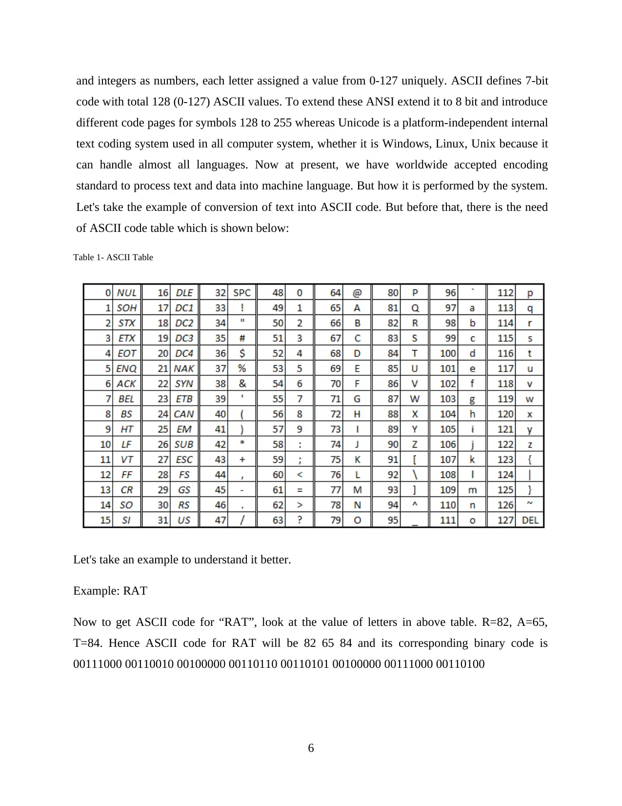
and integers as numbers, each letter assigned a value from 0-127 uniquely. ASCII defines 7-bit
code with total 128 (0-127) ASCII values. To extend these ANSI extend it to 8 bit and introduce
different code pages for symbols 128 to 255 whereas Unicode is a platform-independent internal
text coding system used in all computer system, whether it is Windows, Linux, Unix because it
can handle almost all languages. Now at present, we have worldwide accepted encoding
standard to process text and data into machine language. But how it is performed by the system.
Let's take the example of conversion of text into ASCII code. But before that, there is the need
of ASCII code table which is shown below:
Table 1- ASCII Table
Let's take an example to understand it better.
Example: RAT
Now to get ASCII code for “RAT”, look at the value of letters in above table. R=82, A=65,
T=84. Hence ASCII code for RAT will be 82 65 84 and its corresponding binary code is
00111000 00110010 00100000 00110110 00110101 00100000 00111000 00110100
6
Paraphrase This Document
Need a fresh take? Get an instant paraphrase of this document with our AI Paraphraser
P2. Explain using examples how different types of data can be converted and stored
in computer system
Different data can be stored in computer system like images, audios, videos, text files and all the
specific type have a specific format. Images stored in JPEG (Joint Photographic Experts Group),
JPG (Joint Photographic Group), PNG (Portable Network Graphics), GIF (Graphics Interchange
Format). Similarly, audios in mp3 format and videos in mp4 and text files in various formats like
.txt, .doc depending on requirement. Different type of file format tells user about the file type
without opening it as well as to computer and then instruction is executed to process them. But
how all these are stored in computer and displayed to user (Fisher, 2018).
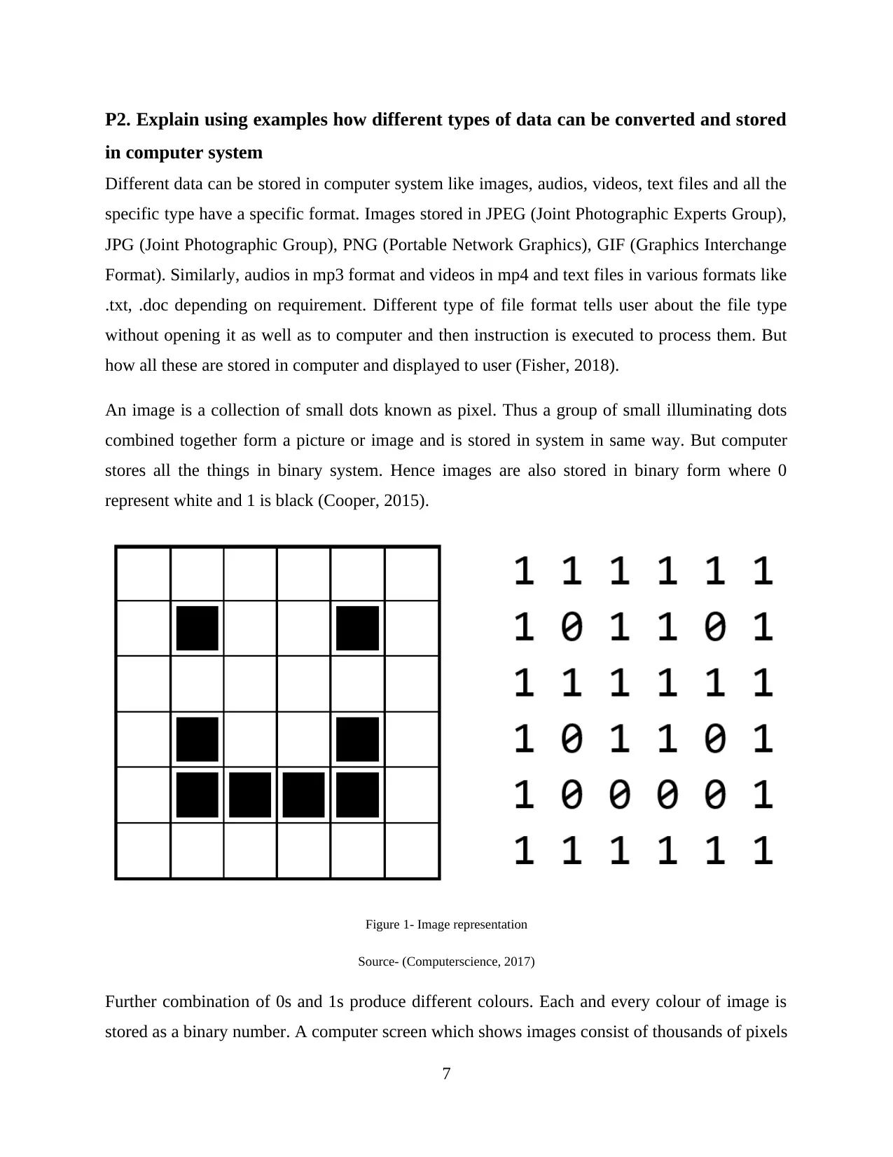
An image is a collection of small dots known as pixel. Thus a group of small illuminating dots
combined together form a picture or image and is stored in system in same way. But computer
stores all the things in binary system. Hence images are also stored in binary form where 0
represent white and 1 is black (Cooper, 2015).
Figure 1- Image representation
Source- (Computerscience, 2017)
Further combination of 0s and 1s produce different colours. Each and every colour of image is
stored as a binary number. A computer screen which shows images consist of thousands of pixels
7
in computer system
Different data can be stored in computer system like images, audios, videos, text files and all the
specific type have a specific format. Images stored in JPEG (Joint Photographic Experts Group),
JPG (Joint Photographic Group), PNG (Portable Network Graphics), GIF (Graphics Interchange
Format). Similarly, audios in mp3 format and videos in mp4 and text files in various formats like
.txt, .doc depending on requirement. Different type of file format tells user about the file type
without opening it as well as to computer and then instruction is executed to process them. But
how all these are stored in computer and displayed to user (Fisher, 2018).
An image is a collection of small dots known as pixel. Thus a group of small illuminating dots
combined together form a picture or image and is stored in system in same way. But computer
stores all the things in binary system. Hence images are also stored in binary form where 0
represent white and 1 is black (Cooper, 2015).
Figure 1- Image representation
Source- (Computerscience, 2017)
Further combination of 0s and 1s produce different colours. Each and every colour of image is
stored as a binary number. A computer screen which shows images consist of thousands of pixels
7
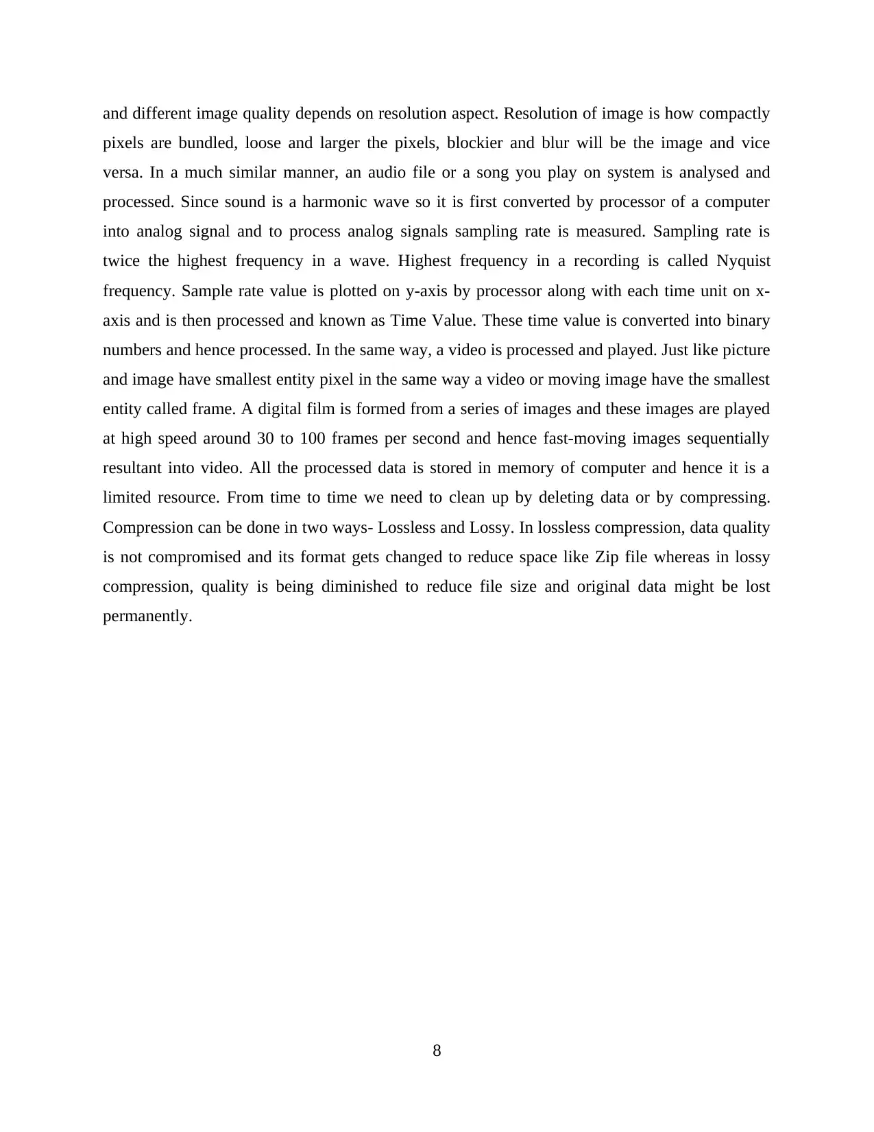
and different image quality depends on resolution aspect. Resolution of image is how compactly
pixels are bundled, loose and larger the pixels, blockier and blur will be the image and vice
versa. In a much similar manner, an audio file or a song you play on system is analysed and
processed. Since sound is a harmonic wave so it is first converted by processor of a computer
into analog signal and to process analog signals sampling rate is measured. Sampling rate is
twice the highest frequency in a wave. Highest frequency in a recording is called Nyquist
frequency. Sample rate value is plotted on y-axis by processor along with each time unit on x-
axis and is then processed and known as Time Value. These time value is converted into binary
numbers and hence processed. In the same way, a video is processed and played. Just like picture
and image have smallest entity pixel in the same way a video or moving image have the smallest
entity called frame. A digital film is formed from a series of images and these images are played
at high speed around 30 to 100 frames per second and hence fast-moving images sequentially
resultant into video. All the processed data is stored in memory of computer and hence it is a
limited resource. From time to time we need to clean up by deleting data or by compressing.
Compression can be done in two ways- Lossless and Lossy. In lossless compression, data quality
is not compromised and its format gets changed to reduce space like Zip file whereas in lossy
compression, quality is being diminished to reduce file size and original data might be lost
permanently.
8
⊘ This is a preview!⊘
Do you want full access?
Subscribe today to unlock all pages.
Trusted by 1+ million students worldwide
P3. Convert numeric data between different number systems including floating
point
To convert any number into another system, we need to keep the base value of the resultant
system. Let's take few different examples of different conversions.
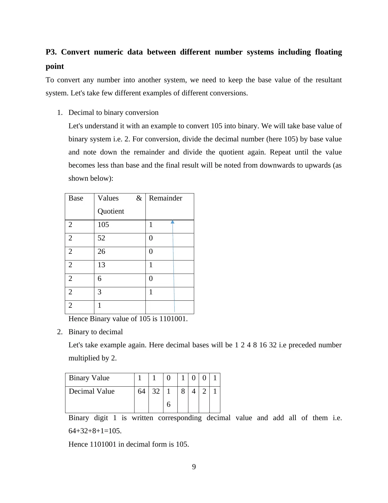
1. Decimal to binary conversion
Let's understand it with an example to convert 105 into binary. We will take base value of
binary system i.e. 2. For conversion, divide the decimal number (here 105) by base value
and note down the remainder and divide the quotient again. Repeat until the value
becomes less than base and the final result will be noted from downwards to upwards (as
shown below):
Base Values &
Quotient
Remainder
2 105 1
2 52 0
2 26 0
2 13 1
2 6 0
2 3 1
2 1
Hence Binary value of 105 is 1101001.
2. Binary to decimal
Let's take example again. Here decimal bases will be 1 2 4 8 16 32 i.e preceded number
multiplied by 2.
Binary Value 1 1 0 1 0 0 1
Decimal Value 64 32 1
6
8 4 2 1
Binary digit 1 is written corresponding decimal value and add all of them i.e.
64+32+8+1=105.
Hence 1101001 in decimal form is 105.
9
point
To convert any number into another system, we need to keep the base value of the resultant
system. Let's take few different examples of different conversions.
1. Decimal to binary conversion
Let's understand it with an example to convert 105 into binary. We will take base value of
binary system i.e. 2. For conversion, divide the decimal number (here 105) by base value
and note down the remainder and divide the quotient again. Repeat until the value
becomes less than base and the final result will be noted from downwards to upwards (as
shown below):
Base Values &
Quotient
Remainder
2 105 1
2 52 0
2 26 0
2 13 1
2 6 0
2 3 1
2 1
Hence Binary value of 105 is 1101001.
2. Binary to decimal
Let's take example again. Here decimal bases will be 1 2 4 8 16 32 i.e preceded number
multiplied by 2.
Binary Value 1 1 0 1 0 0 1
Decimal Value 64 32 1
6
8 4 2 1
Binary digit 1 is written corresponding decimal value and add all of them i.e.
64+32+8+1=105.
Hence 1101001 in decimal form is 105.
9
Paraphrase This Document
Need a fresh take? Get an instant paraphrase of this document with our AI Paraphraser
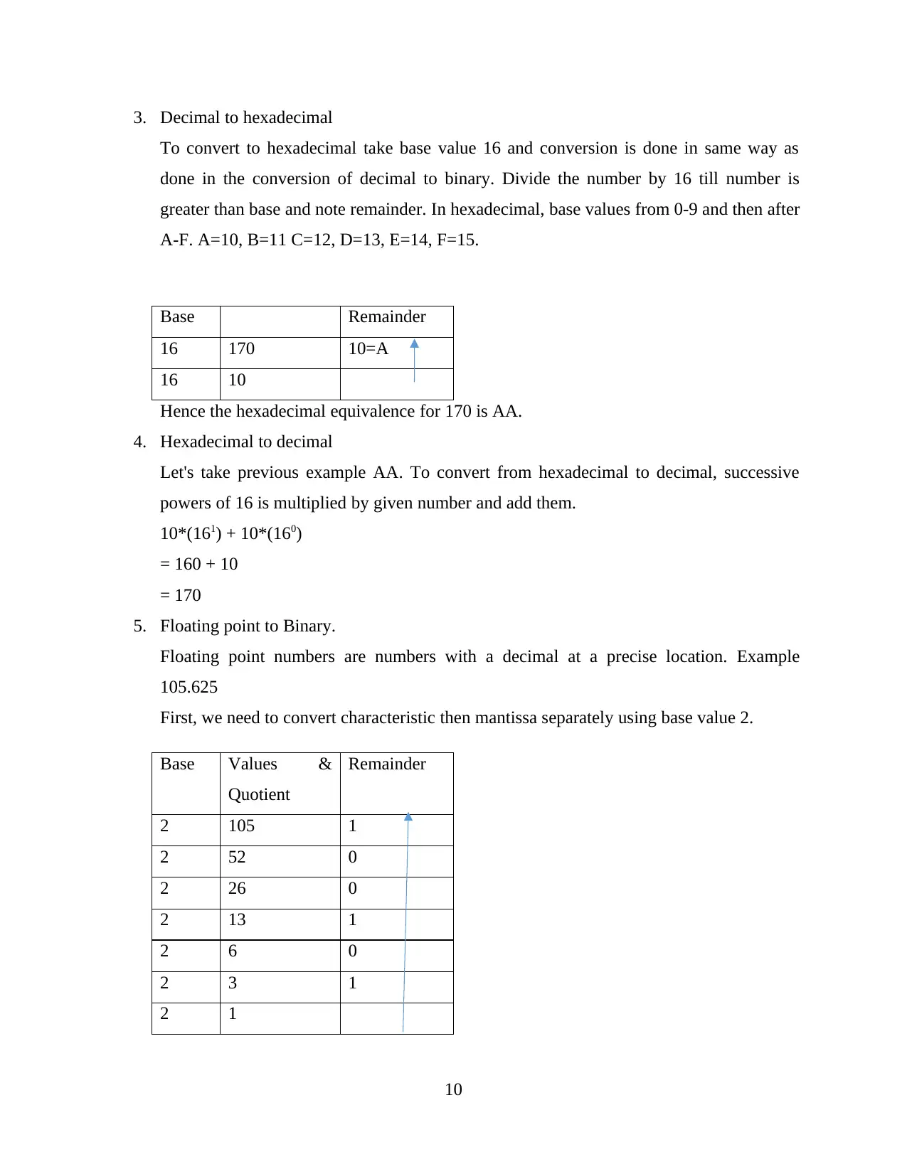
3. Decimal to hexadecimal
To convert to hexadecimal take base value 16 and conversion is done in same way as
done in the conversion of decimal to binary. Divide the number by 16 till number is
greater than base and note remainder. In hexadecimal, base values from 0-9 and then after
A-F. A=10, B=11 C=12, D=13, E=14, F=15.
Base Remainder
16 170 10=A
16 10
Hence the hexadecimal equivalence for 170 is AA.
4. Hexadecimal to decimal
Let's take previous example AA. To convert from hexadecimal to decimal, successive
powers of 16 is multiplied by given number and add them.
10*(161) + 10*(160)
= 160 + 10
= 170
5. Floating point to Binary.
Floating point numbers are numbers with a decimal at a precise location. Example
105.625
First, we need to convert characteristic then mantissa separately using base value 2.
Base Values &
Quotient
Remainder
2 105 1
2 52 0
2 26 0
2 13 1
2 6 0
2 3 1
2 1
10
Now we need to convert mantissa and while converting mantissa, base value is multiplied
to mantissa and characteristic is noted.
11
to mantissa and characteristic is noted.
11
⊘ This is a preview!⊘
Do you want full access?
Subscribe today to unlock all pages.
Trusted by 1+ million students worldwide
1 out of 36
Related Documents


Your All-in-One AI-Powered Toolkit for Academic Success.
+13062052269
info@desklib.com
Available 24*7 on WhatsApp / Email
![[object Object]](/_next/static/media/star-bottom.7253800d.svg)
Unlock your academic potential
Copyright © 2020–2026 A2Z Services. All Rights Reserved. Developed and managed by ZUCOL.