Traffic Light Controller Implementation
VerifiedAdded on 2023/04/19
|11
|1543
|154
AI Summary
This document provides a detailed explanation of the implementation of a traffic light controller using state transitions and flip flops. It includes information on the HDL code, test bench, simulation results, and design summary.
Contribute Materials
Your contribution can guide someone’s learning journey. Share your
documents today.
Contents
Introduction:...............................................................................................................................................2
State Diagram:.............................................................................................................................................2
State Table:..................................................................................................................................................2
Implementation:..........................................................................................................................................3
HDL Code:....................................................................................................................................................4
Test Bench:..................................................................................................................................................9
Simulation Results:....................................................................................................................................10
Design Summary:.......................................................................................................................................10
Dataflow Diagram:.....................................................................................................................................10
Secure Best Marks with AI Grader
Need help grading? Try our AI Grader for instant feedback on your assignments.
Introduction:
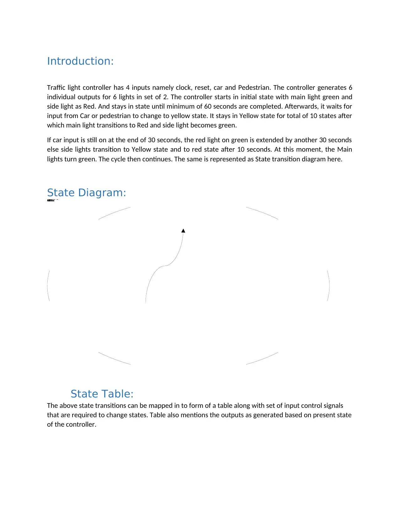
Traffic light controller has 4 inputs namely clock, reset, car and Pedestrian. The controller generates 6
individual outputs for 6 lights in set of 2. The controller starts in initial state with main light green and
side light as Red. And stays in state until minimum of 60 seconds are completed. Afterwards, it waits for
input from Car or pedestrian to change to yellow state. It stays in Yellow state for total of 10 states after
which main light transitions to Red and side light becomes green.
If car input is still on at the end of 30 seconds, the red light on green is extended by another 30 seconds
else side lights transition to Yellow state and to red state after 10 seconds. At this moment, the Main
lights turn green. The cycle then continues. The same is represented as State transition diagram here.
State Diagram:
State Table:
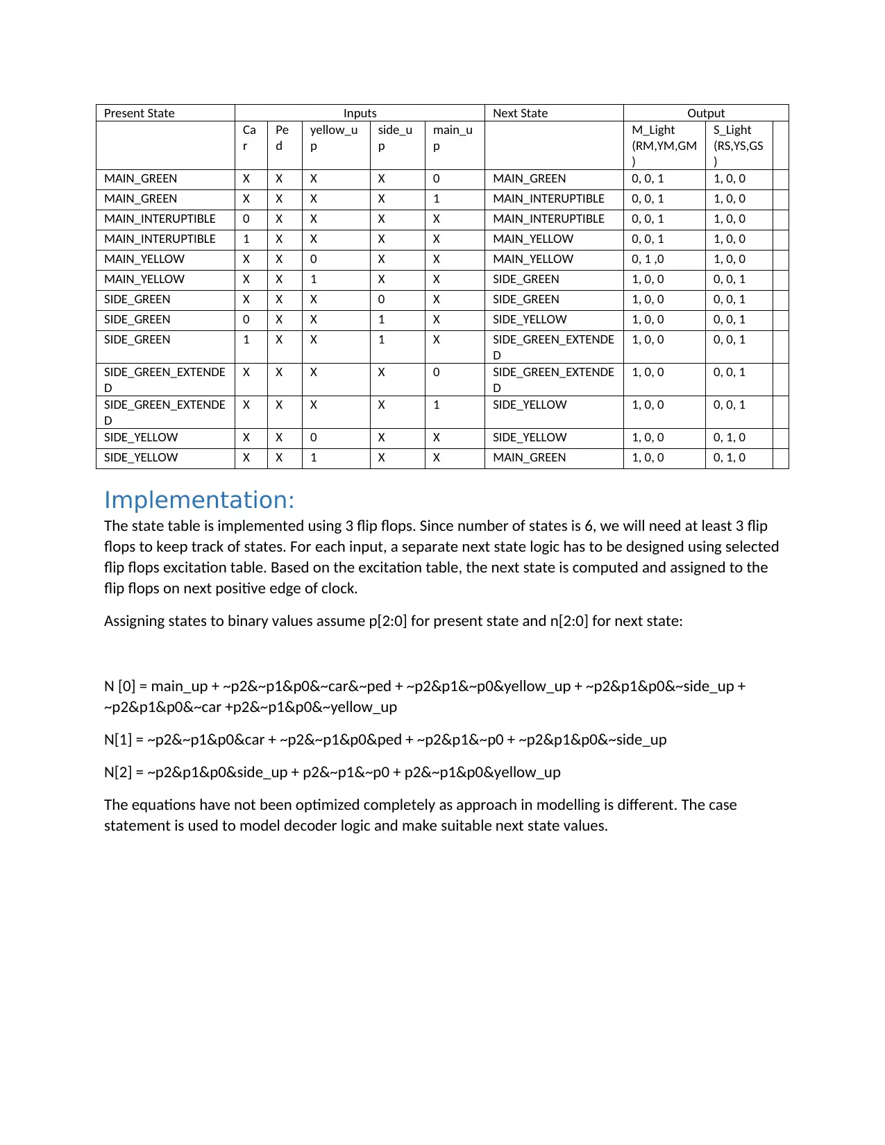
The above state transitions can be mapped in to form of a table along with set of input control signals
that are required to change states. Table also mentions the outputs as generated based on present state
of the controller.
Main_GreenMain_InteruptibleMain_YellowMain_Red,Side_GreenSide_YellowSide_extended
Present State Inputs Next State Output
Ca
r
Pe
d
yellow_u
p
side_u
p
main_u
p
M_Light
(RM,YM,GM
)
S_Light
(RS,YS,GS
)
MAIN_GREEN X X X X 0 MAIN_GREEN 0, 0, 1 1, 0, 0
MAIN_GREEN X X X X 1 MAIN_INTERUPTIBLE 0, 0, 1 1, 0, 0
MAIN_INTERUPTIBLE 0 X X X X MAIN_INTERUPTIBLE 0, 0, 1 1, 0, 0
MAIN_INTERUPTIBLE 1 X X X X MAIN_YELLOW 0, 0, 1 1, 0, 0
MAIN_YELLOW X X 0 X X MAIN_YELLOW 0, 1 ,0 1, 0, 0
MAIN_YELLOW X X 1 X X SIDE_GREEN 1, 0, 0 0, 0, 1
SIDE_GREEN X X X 0 X SIDE_GREEN 1, 0, 0 0, 0, 1
SIDE_GREEN 0 X X 1 X SIDE_YELLOW 1, 0, 0 0, 0, 1
SIDE_GREEN 1 X X 1 X SIDE_GREEN_EXTENDE
D
1, 0, 0 0, 0, 1
SIDE_GREEN_EXTENDE
D
X X X X 0 SIDE_GREEN_EXTENDE
D
1, 0, 0 0, 0, 1
SIDE_GREEN_EXTENDE
D
X X X X 1 SIDE_YELLOW 1, 0, 0 0, 0, 1
SIDE_YELLOW X X 0 X X SIDE_YELLOW 1, 0, 0 0, 1, 0
SIDE_YELLOW X X 1 X X MAIN_GREEN 1, 0, 0 0, 1, 0
Implementation:
The state table is implemented using 3 flip flops. Since number of states is 6, we will need at least 3 flip
flops to keep track of states. For each input, a separate next state logic has to be designed using selected
flip flops excitation table. Based on the excitation table, the next state is computed and assigned to the
flip flops on next positive edge of clock.
Assigning states to binary values assume p[2:0] for present state and n[2:0] for next state:
N [0] = main_up + ~p2&~p1&p0&~car&~ped + ~p2&p1&~p0&yellow_up + ~p2&p1&p0&~side_up +
~p2&p1&p0&~car +p2&~p1&p0&~yellow_up
N[1] = ~p2&~p1&p0&car + ~p2&~p1&p0&ped + ~p2&p1&~p0 + ~p2&p1&p0&~side_up
N[2] = ~p2&p1&p0&side_up + p2&~p1&~p0 + p2&~p1&p0&yellow_up
The equations have not been optimized completely as approach in modelling is different. The case
statement is used to model decoder logic and make suitable next state values.
HDL Code:
`timescale 1ns / 1ns
//////////////////////////////////////////////////////////////////////////////////
// Company:
// Engineer:
//
// Create Date:
// Design Name:
// Module Name: TrafficLight
// Project Name:
// Target Devices:
// Tool versions:
// Description:
//
// Dependencies:
//
// Revision:
// Revision 0.01 - File Created
// Additional Comments:
//
//////////////////////////////////////////////////////////////////////////////////
module TrafficLight(car,ped,reset,clk,RM,YM,GM,RS,YS,GS);
// inputs to DUT
input car,ped,reset,clk;
// OUTPUT from DUT
output RM,YM,GM,RS,YS,GS;
reg [5:0] main_counter;
wire main_up;
reg main_start;
Secure Best Marks with AI Grader
Need help grading? Try our AI Grader for instant feedback on your assignments.
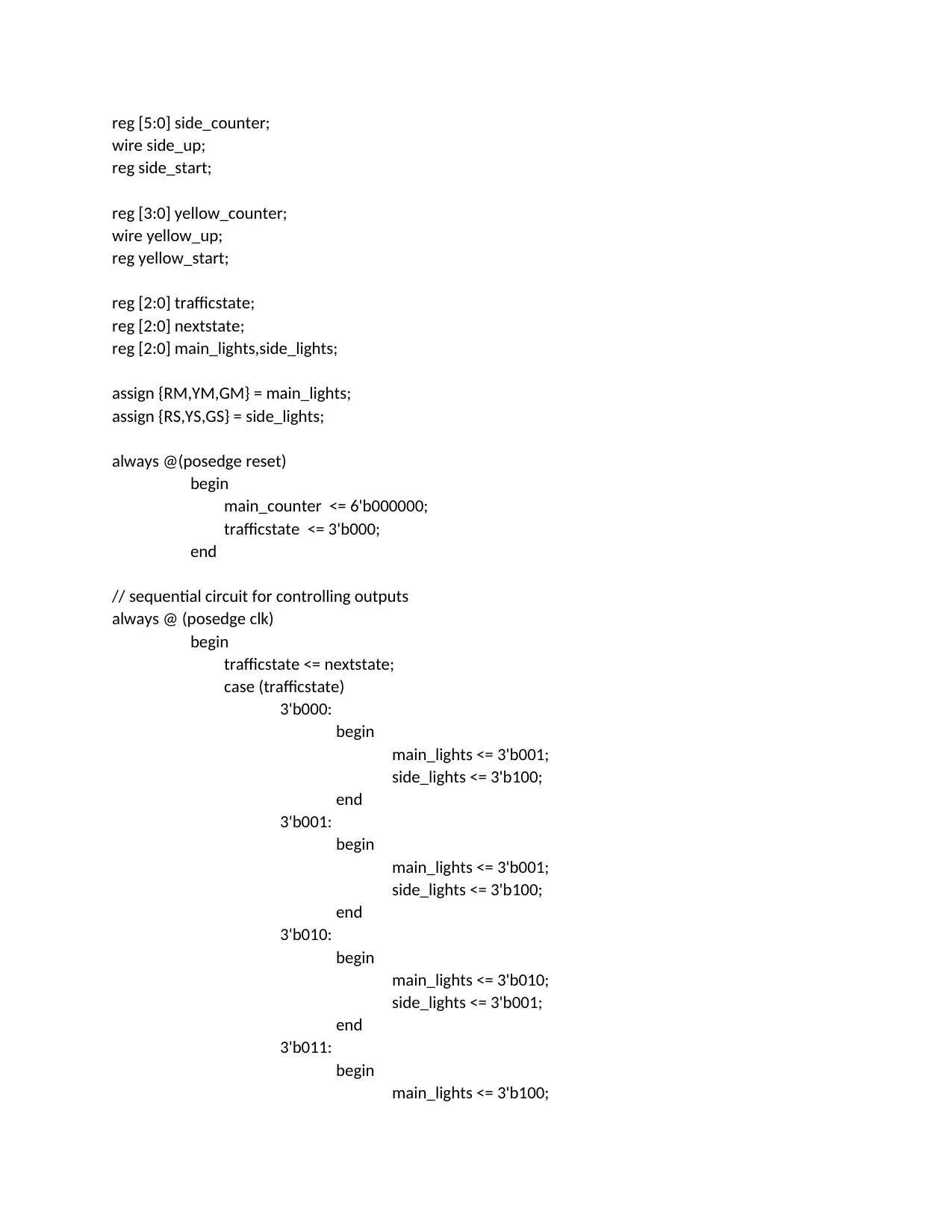
reg [5:0] side_counter;
wire side_up;
reg side_start;
reg [3:0] yellow_counter;
wire yellow_up;
reg yellow_start;
reg [2:0] trafficstate;
reg [2:0] nextstate;
reg [2:0] main_lights,side_lights;
assign {RM,YM,GM} = main_lights;
assign {RS,YS,GS} = side_lights;
always @(posedge reset)
begin
main_counter <= 6'b000000;
trafficstate <= 3'b000;
end
// sequential circuit for controlling outputs
always @ (posedge clk)
begin
trafficstate <= nextstate;
case (trafficstate)
3'b000:
begin
main_lights <= 3'b001;
side_lights <= 3'b100;
end
3'b001:
begin
main_lights <= 3'b001;
side_lights <= 3'b100;
end
3'b010:
begin
main_lights <= 3'b010;
side_lights <= 3'b001;
end
3'b011:
begin
main_lights <= 3'b100;
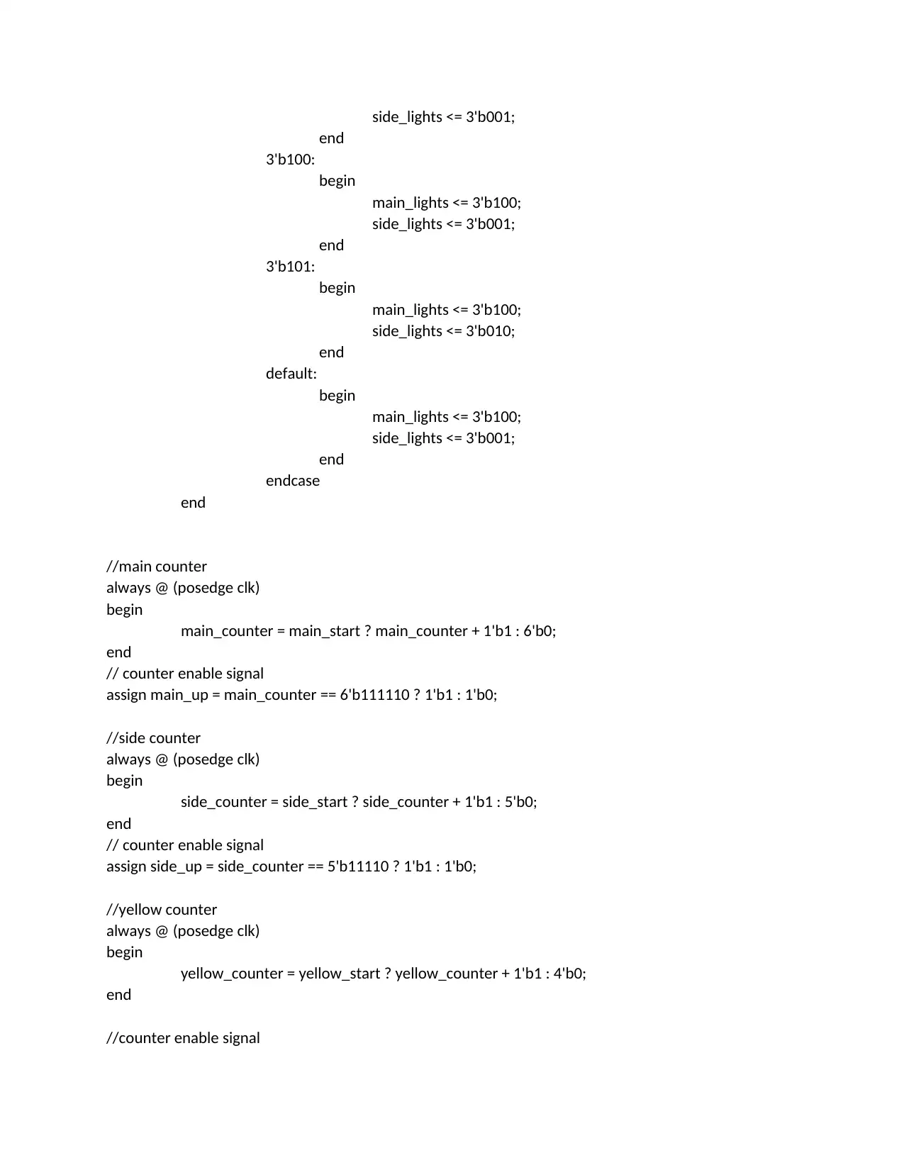
side_lights <= 3'b001;
end
3'b100:
begin
main_lights <= 3'b100;
side_lights <= 3'b001;
end
3'b101:
begin
main_lights <= 3'b100;
side_lights <= 3'b010;
end
default:
begin
main_lights <= 3'b100;
side_lights <= 3'b001;
end
endcase
end
//main counter
always @ (posedge clk)
begin
main_counter = main_start ? main_counter + 1'b1 : 6'b0;
end
// counter enable signal
assign main_up = main_counter == 6'b111110 ? 1'b1 : 1'b0;
//side counter
always @ (posedge clk)
begin
side_counter = side_start ? side_counter + 1'b1 : 5'b0;
end
// counter enable signal
assign side_up = side_counter == 5'b11110 ? 1'b1 : 1'b0;
//yellow counter
always @ (posedge clk)
begin
yellow_counter = yellow_start ? yellow_counter + 1'b1 : 4'b0;
end
//counter enable signal
end
3'b100:
begin
main_lights <= 3'b100;
side_lights <= 3'b001;
end
3'b101:
begin
main_lights <= 3'b100;
side_lights <= 3'b010;
end
default:
begin
main_lights <= 3'b100;
side_lights <= 3'b001;
end
endcase
end
//main counter
always @ (posedge clk)
begin
main_counter = main_start ? main_counter + 1'b1 : 6'b0;
end
// counter enable signal
assign main_up = main_counter == 6'b111110 ? 1'b1 : 1'b0;
//side counter
always @ (posedge clk)
begin
side_counter = side_start ? side_counter + 1'b1 : 5'b0;
end
// counter enable signal
assign side_up = side_counter == 5'b11110 ? 1'b1 : 1'b0;
//yellow counter
always @ (posedge clk)
begin
yellow_counter = yellow_start ? yellow_counter + 1'b1 : 4'b0;
end
//counter enable signal
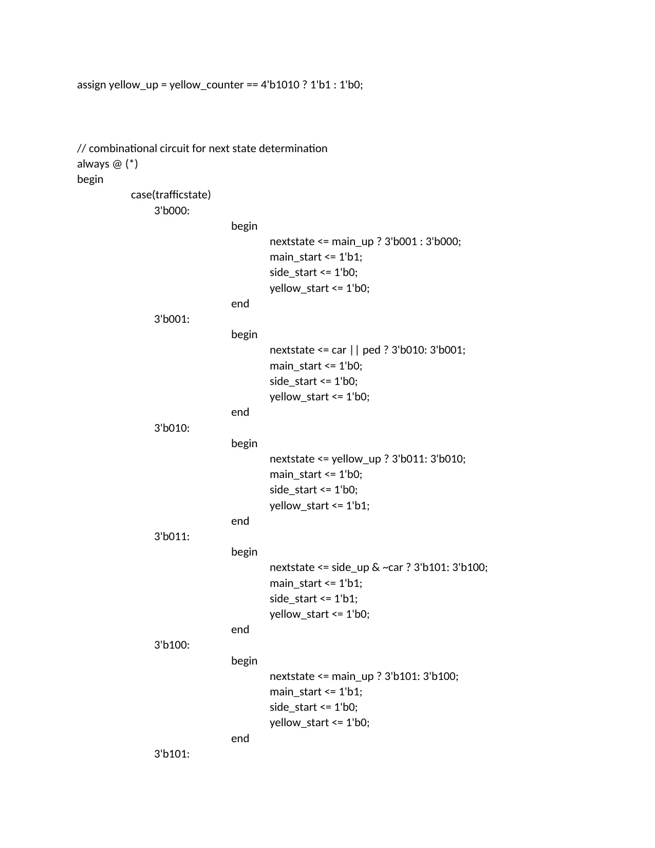
assign yellow_up = yellow_counter == 4'b1010 ? 1'b1 : 1'b0;
// combinational circuit for next state determination
always @ (*)
begin
case(trafficstate)
3'b000:
begin
nextstate <= main_up ? 3'b001 : 3'b000;
main_start <= 1'b1;
side_start <= 1'b0;
yellow_start <= 1'b0;
end
3'b001:
begin
nextstate <= car || ped ? 3'b010: 3'b001;
main_start <= 1'b0;
side_start <= 1'b0;
yellow_start <= 1'b0;
end
3'b010:
begin
nextstate <= yellow_up ? 3'b011: 3'b010;
main_start <= 1'b0;
side_start <= 1'b0;
yellow_start <= 1'b1;
end
3'b011:
begin
nextstate <= side_up & ~car ? 3'b101: 3'b100;
main_start <= 1'b1;
side_start <= 1'b1;
yellow_start <= 1'b0;
end
3'b100:
begin
nextstate <= main_up ? 3'b101: 3'b100;
main_start <= 1'b1;
side_start <= 1'b0;
yellow_start <= 1'b0;
end
3'b101:
Paraphrase This Document
Need a fresh take? Get an instant paraphrase of this document with our AI Paraphraser
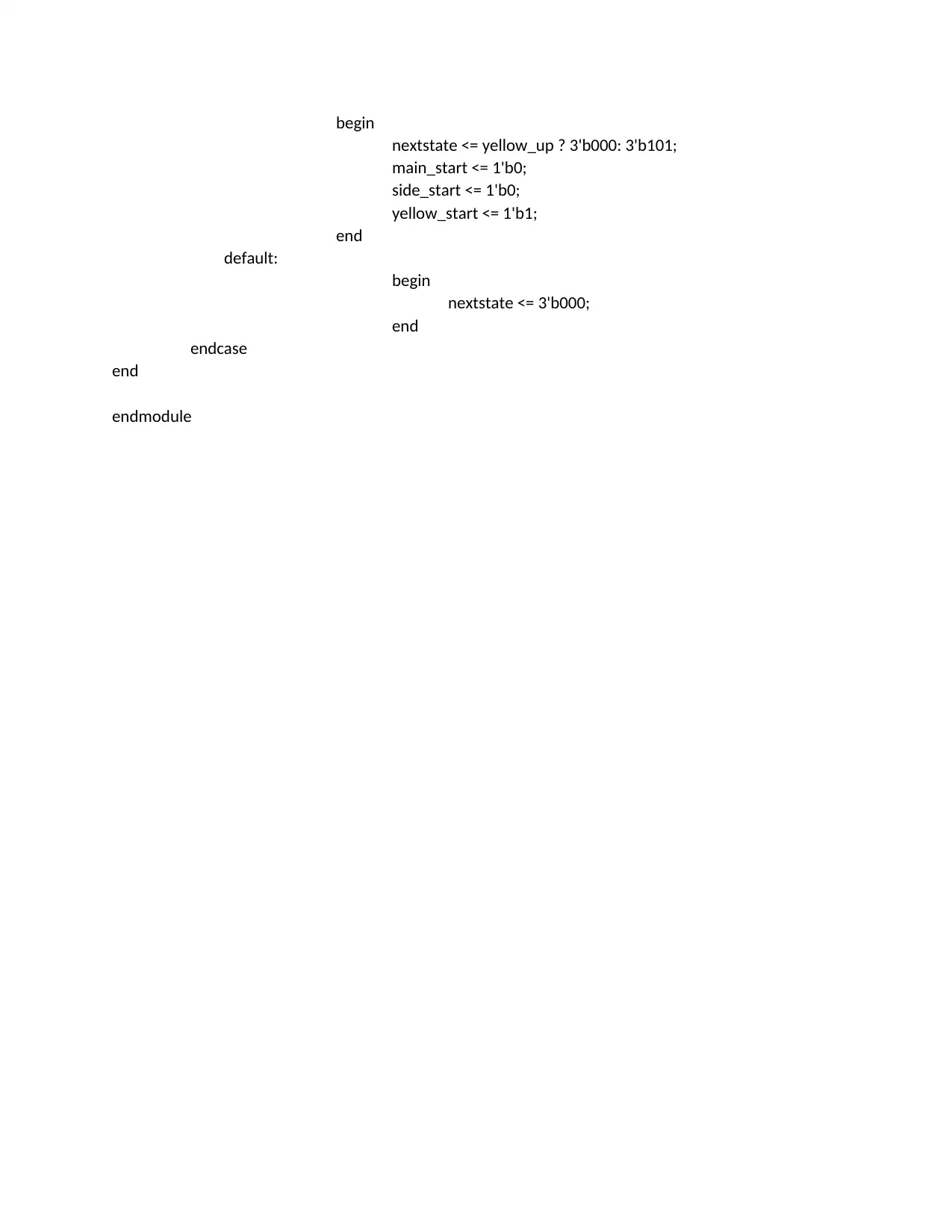
begin
nextstate <= yellow_up ? 3'b000: 3'b101;
main_start <= 1'b0;
side_start <= 1'b0;
yellow_start <= 1'b1;
end
default:
begin
nextstate <= 3'b000;
end
endcase
end
endmodule
nextstate <= yellow_up ? 3'b000: 3'b101;
main_start <= 1'b0;
side_start <= 1'b0;
yellow_start <= 1'b1;
end
default:
begin
nextstate <= 3'b000;
end
endcase
end
endmodule
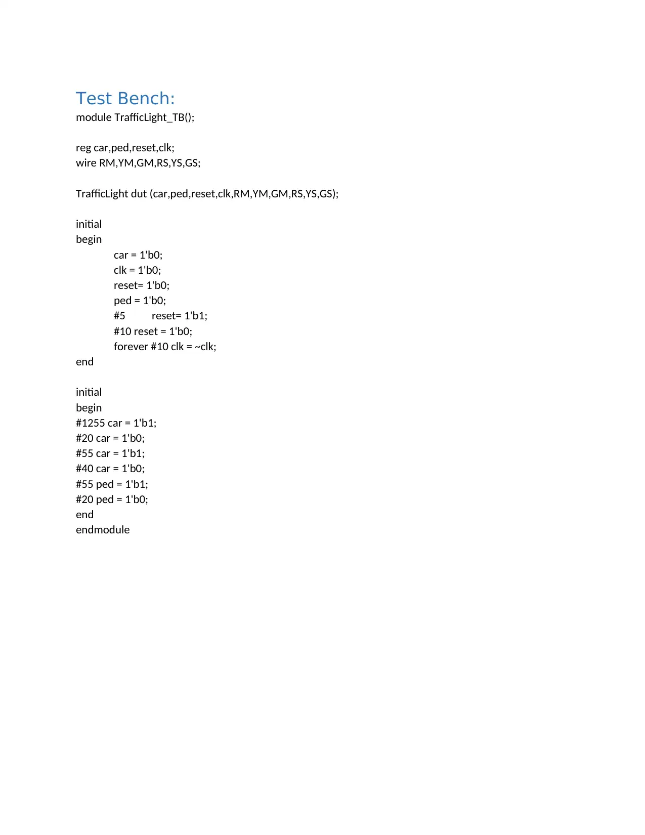
Test Bench:
module TrafficLight_TB();
reg car,ped,reset,clk;
wire RM,YM,GM,RS,YS,GS;
TrafficLight dut (car,ped,reset,clk,RM,YM,GM,RS,YS,GS);
initial
begin
car = 1'b0;
clk = 1'b0;
reset= 1'b0;
ped = 1'b0;
#5 reset= 1'b1;
#10 reset = 1'b0;
forever #10 clk = ~clk;
end
initial
begin
#1255 car = 1'b1;
#20 car = 1'b0;
#55 car = 1'b1;
#40 car = 1'b0;
#55 ped = 1'b1;
#20 ped = 1'b0;
end
endmodule
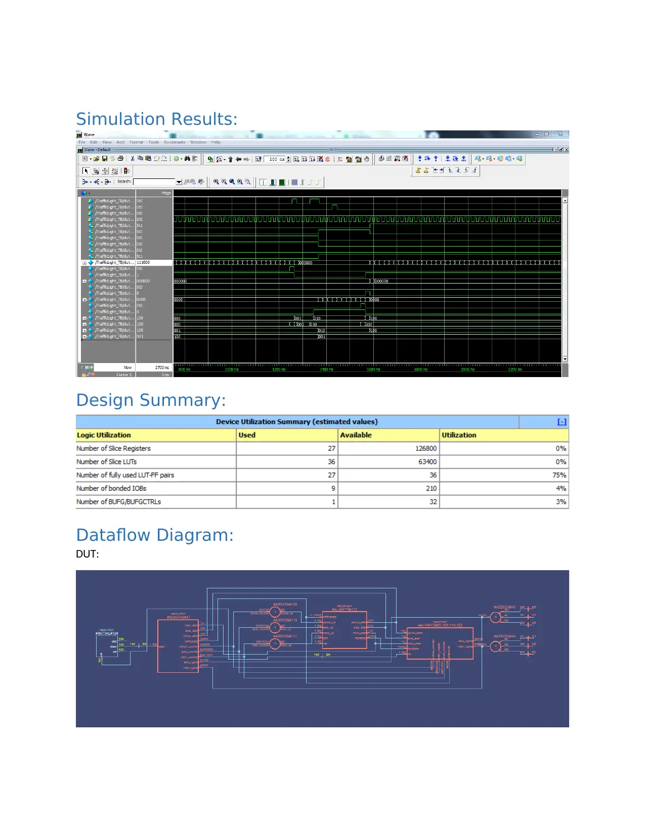
Simulation Results:
Design Summary:
Dataflow Diagram:
DUT:
Design Summary:
Dataflow Diagram:
DUT:
Secure Best Marks with AI Grader
Need help grading? Try our AI Grader for instant feedback on your assignments.
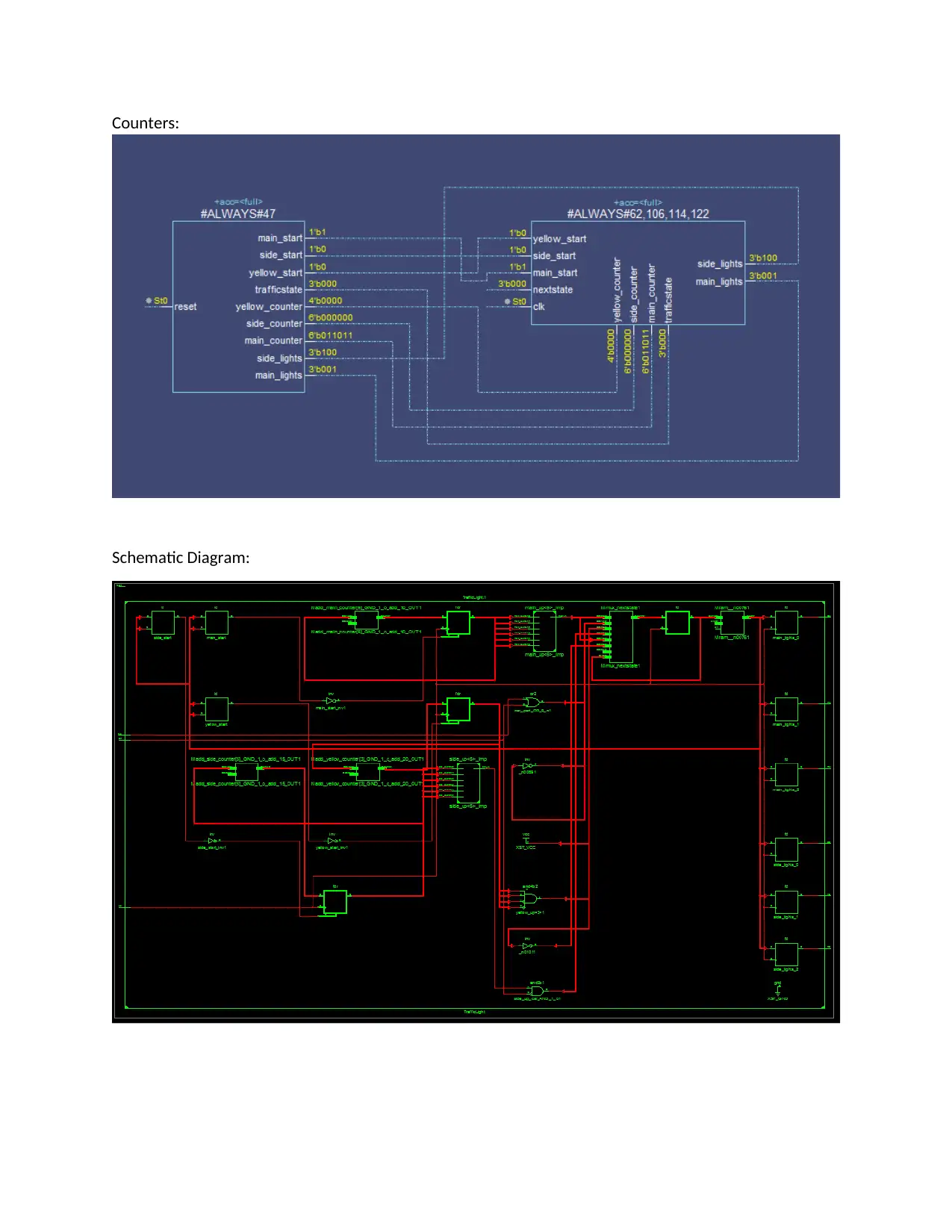
Counters:
Schematic Diagram:
Schematic Diagram:
1 out of 11
Related Documents
Your All-in-One AI-Powered Toolkit for Academic Success.
+13062052269
info@desklib.com
Available 24*7 on WhatsApp / Email
![[object Object]](/_next/static/media/star-bottom.7253800d.svg)
Unlock your academic potential
© 2024 | Zucol Services PVT LTD | All rights reserved.


