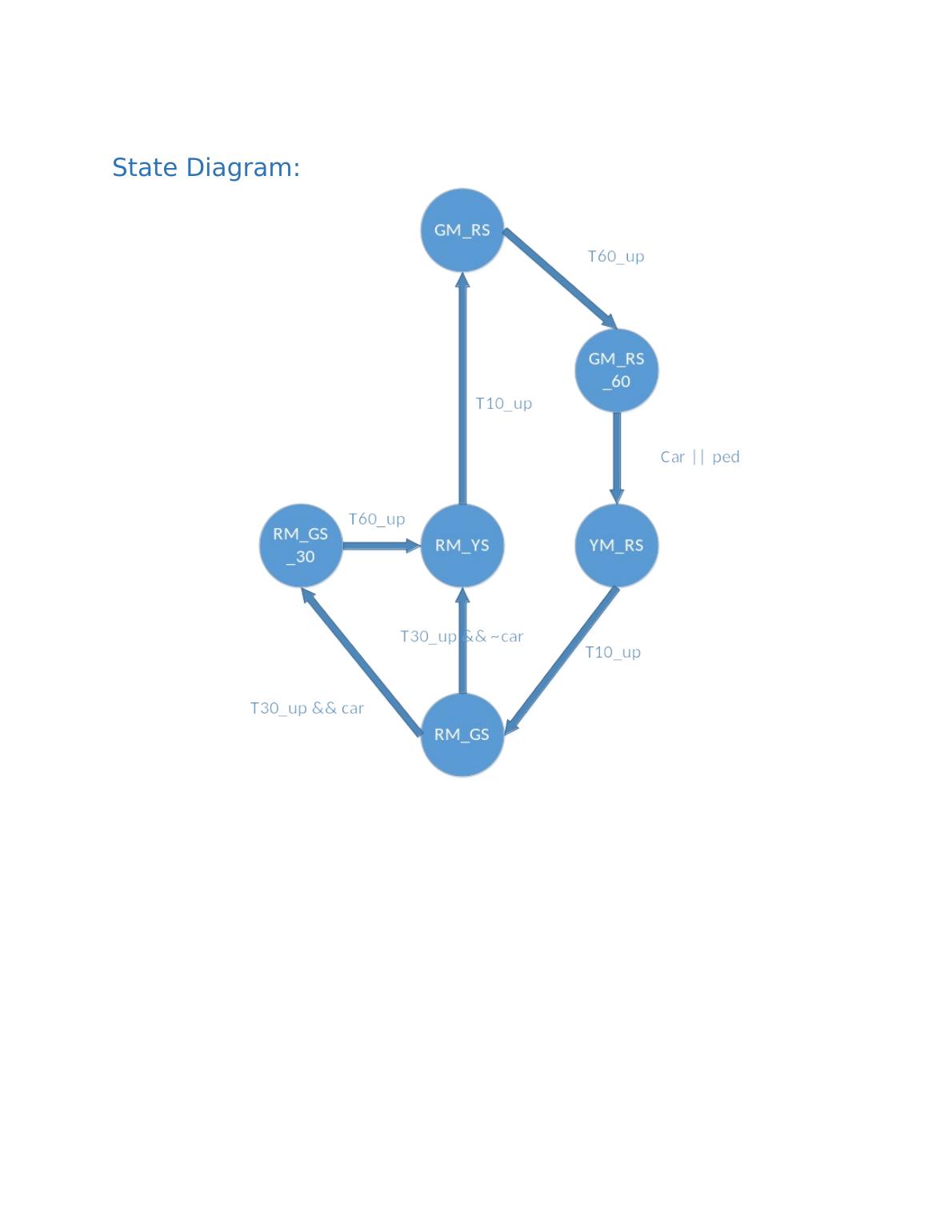
logo

State Diagram:.

Design a traffic light controller for an intersection between a Main Road and a Side Street, including state diagram, implementation, and verification.

13 Pages839 Words100 Views
   

Added on  2023-04-06

State Diagram:.

Design a traffic light controller for an intersection between a Main Road and a Side Street, including state diagram, implementation, and verification.

   Added on 2023-04-06

ShareRelated Documents
State Diagram:
State Diagram:._1
State Table:
Present
State
Inputs Next State Output
Car Ped T10_u
p
T30_up T60_up M_Light
(RM,YM,GM
)
S_Light
(RS,YS,GS)
GM_RS X X X X 0 GM_RS 001 100
GM_RS X X X X 1 GM_RS_60 001 100
GM_RS_60 0 X X X X GM_RS_60 001 100
GM_RS_60 1 X X X X YM_RS 001 100
YM_RS X X 0 X X YM_RS 010 100
YM_RS X X 1 X X RM_GS 100 001
RM_GS X X X 0 X RM_GS 100 001
RM_GS 0 X X 1 X RM_YS 100 001
RM_GS 1 X X 1 X RM_GS_30 100 001
RM_GS_30 X X X X 0 RM_GS_30 100 001
RM_GS_30 X X X X 1 RM_YS 100 001
RM_YS X X 0 X X RM_YS 100 010
RM_YS X X 1 X X GM_RS 100 010
Design Approach:
D flip flips shall be used to design sequential components in the circuit related to FSM. Other
combinational logic shall be achieved using multiplexer and basic gates. Output of flip flops would for
the present state of the circuit. Based on this value one of the input lines from mux input shall be
transferred to output. Since present state acts as select line, input would mimic the logic of next state by
combining input signals and present state value. The outputs shall be derived from present state using
decoders.
Since we have 6 states, 3 flip flops will be required for modelling the FSM. Each flip flop has its own
input for next state.
3
D -Flip
Flops
Main Light
Decoder
Side Light
Decoder
MUX
8 x 3
Next State
Control
Present
State Main Way
Side Way
State Diagram:._2
HDL Code:
`timescale 1ns / 1ns
module TrafficLight(car,ped,reset,clk,RM,YM,GM,RS,YS,GS);
input car,ped,reset,clk;
output RM,YM,GM,RS,YS,GS;
// Counter values set for time
localparam t10 = 4'b1010;
localparam t30 = 5'b11110;
localparam t60 = 6'b111100;
//FSM States
localparam GM_RS = 3'b000;
localparam GM_RS_60 = 3'b001;
localparam YM_RS = 3'b010;
localparam RM_GS = 3'b011;
localparam RM_GS_30 = 3'b100;
localparam RM_YS = 3'b101;
// Counter variables and registers
reg [5:0] counter_t60;
wire t60_up;
State Diagram:._3
reg start_t60;
reg [5:0] counter_t30;
wire t30_up;
reg start_t30;
reg [3:0] counter_t10;
wire t10_up;
reg start_t10;
FSM Registers
reg [2:0] trafficstate;
reg [2:0] nextstate;
reg [2:0] M_Light,S_Light;
// Output Values
assign {RM,YM,GM} = M_Light;
assign {RS,YS,GS} = S_Light;
// Reset Circuit
always @(posedge reset)
begin
M_Light <= 3'b001;
S_Light <= 3'b100;
counter_t60 <= 6'b000000;
counter_t30 <= 5'b00000;
counter_t10 <= 4'b0000;
trafficstate <= 3'b001;
State Diagram:._4

End of preview

Want to access all the pages? Upload your documents or become a member.

Related Documents
Traffic Light Controller Implementation
|11
|1543
|154

VHDL Assignment: Register File Implementation in VHDL
|4
|928
|211