UOW ITC548 System Analysis: Data Flow Diagram and System Design Report
VerifiedAdded on 2023/06/11
|8
|1288
|496
Report
AI Summary
This report provides a detailed analysis of data flow diagrams (DFD) in the context of system analysis and design. It explains the purpose of DFDs, their relation to system scope and boundaries, and illustrates their application using a mortgage broker system example. The report differentiates between logical and physical DFDs, discusses system vision documents, and explores the use of activity diagrams in user interface design. It also includes a plain English explanation of a customer account creation diagram and converts an activity diagram into a narrative use case description for a stock management system. The document references various sources to support its explanations and is intended to provide a comprehensive understanding of DFDs and their role in system development. Desklib provides access to this and other solved assignments.

Running head: Data Flow diagram 1
Data Flow Diagram
Name of the Student:
Name of the Institution:
Data Flow Diagram
Name of the Student:
Name of the Institution:
Paraphrase This Document
Need a fresh take? Get an instant paraphrase of this document with our AI Paraphraser
Data Flow diagram 2
System Analysis
What is the purpose of DFD and how is it related to the concept of scope and boundary
conditions?
A data flow diagram refers to a traditional tool used to visually and
graphically/diagrammatically represent flow of information within a system, and between the
different interacting units and actors as defined by the system (Visual Paradigm, 2012). It is a
model perspective of a system that uses graphical representation tools to make users understand
how information flows through the system, and the activities that trigger processing of such
information.
The purpose of this model is to enable the project team, clients and expected system users
to effectively work together during the analysis and requirements specification and elicitation
phases of software development.
Software engineers use Data flow Diagrams to represent processes, data flows, and
external entities and data stores. Processes consists of all activities that are carried out by system,
and through which information is used and equally transformed. Data-flows refers to the inputs
and associated/ corresponding outputs from these processes, while external entities are denoted
using ovals and represent sources of information and its recipients and data stores show where
this information is stored after complete execution/processing.
By defining and representing system requirements and info flow graphically, software
engineers depict scope and system boundaries as a whole. This is achieved by defining and
representing all system activities, and what each actor/entity is capable of doing within the
system and showing results of such executions.
Data Flow diagram 3
Mortgage broker
For the mortgage broker system DFD, the broker could be represented as a set of multiple
processes since they only creates outputs rather than inputs to the system. In this business
scenario, the mortgage broker acts as an intermediary between a loaning firm’s system and a
clients. The primary source of information is the business offering the service and the customer
requesting for the mortgage, and hence they (mortgage brokers) will be represented using
multiple processes through which they interact with the customer and the business, presenting
customer requests to the system, and outputs of such requests to the customer. These processes
are therefore represented as a series of sequential processes.
Constructing a logical DFD
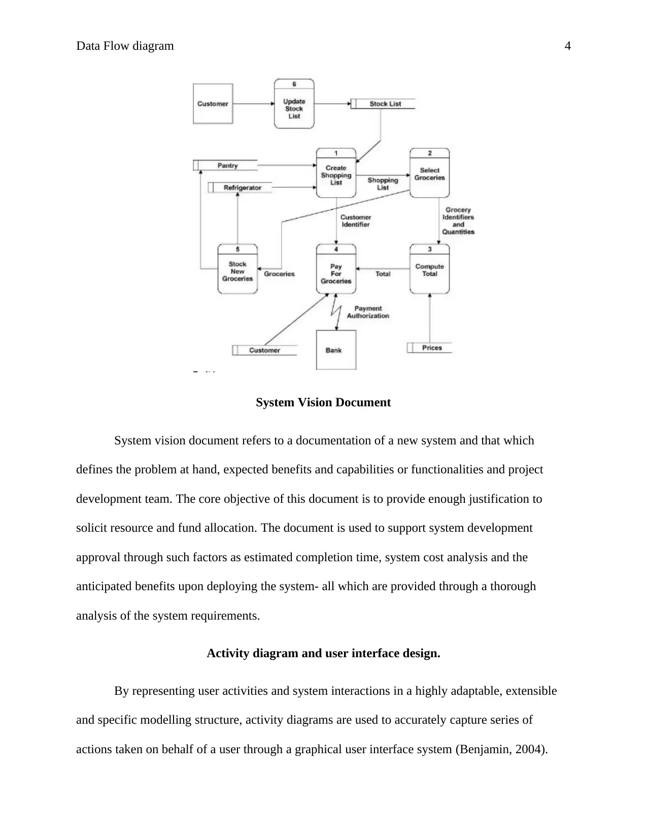
A physical Data Flow Diagram represents the actors performing respective actions. In the
shopping data flow diagram provided, the customer is represented as an external entity that
performs two processes in a linear sequence. To the contrary, a logical Data Flow Diagram
references to the customer- who is performing the actions by explicitly representing the Stock
list- which in this case is the data store, rather than within the logic of Select groceries process.
Furthermore, processes in the physical data flow diagram are now represented in parallel due to
the fact that logical representation separates the physical groceries from their respective
information content.
⊘ This is a preview!⊘
Do you want full access?
Subscribe today to unlock all pages.

Trusted by 1+ million students worldwide
Data Flow diagram 4
System Vision Document
System vision document refers to a documentation of a new system and that which
defines the problem at hand, expected benefits and capabilities or functionalities and project
development team. The core objective of this document is to provide enough justification to
solicit resource and fund allocation. The document is used to support system development
approval through such factors as estimated completion time, system cost analysis and the
anticipated benefits upon deploying the system- all which are provided through a thorough
analysis of the system requirements.
Activity diagram and user interface design.
By representing user activities and system interactions in a highly adaptable, extensible
and specific modelling structure, activity diagrams are used to accurately capture series of
actions taken on behalf of a user through a graphical user interface system (Benjamin, 2004).
Paraphrase This Document
Need a fresh take? Get an instant paraphrase of this document with our AI Paraphraser
Data Flow diagram 5
Activity diagrams use icons to represent and visually differentiate the various activities and
processes that take place within a system. Presentation activities in the diagrams are an important
abstract of user interface details. Additionally, the representation creates system exceptions that
show error conditions that might occur due to unusual activity in the system. This is very
important when designing and indicating system logging and error recovery techniques
(Ebitisam & Mohamed, 2015).
Activity diagrams represent system activities and externally describe business processes
in a parallel way, and uses common display formats to model such processes thus making it easy
to design user interfaces (SOURCE MAKING, n.d.).
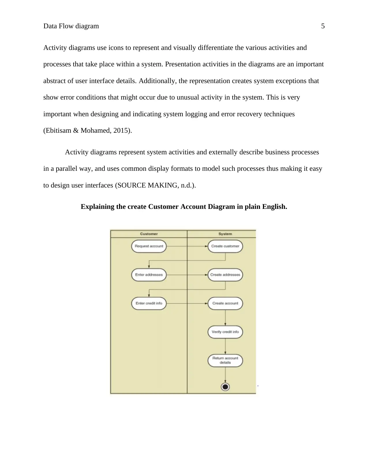
Explaining the create Customer Account Diagram in plain English.
Data Flow diagram 6
In the above system, we have two actors, the customer from the front end and the system
itself at the back end.
The customer sends a request, through the system’s interface to create account and the
system responds to this request by creating a new customer instance, and sending them with a
form to fill/enter their addresses. The customer enters the addresses, sends them to the system.
Once this is completed, the system asks the customer to fill in their credit information. The
system in turn validates user details and returns stores accounts details in its system database
before terminating the processes.
From this scenario, the processes involved are triggered by the customer’s act of
requesting for an account. Equally, data and information flowing through the system originates
from them.
Convert the following activity diagram into narrative form, describing the interaction
between the clerk and the system, in the flow of activities section of the fully developed use
case description below
In a stock management system, the customer, clerk/cashier interact with the system with the
clerk acting as a mediator between the customer and the system.
The clerk provides information regarding items that the customer has presented for checkout and
the system responds by searching through itself if they actually are in stock. For successful item
search, the system goes ahead to display each item’s price and description. After doing this, it
then prints out a receipt of the transaction indicating total payable amount and present this
information to the clerk. The clerk forwards these details to the customer. The customer either
choses to use cash or credit card to pay for the goods. If credit card fails and the clients has no
⊘ This is a preview!⊘
Do you want full access?
Subscribe today to unlock all pages.

Trusted by 1+ million students worldwide

Data Flow diagram 7
cash, then the clerk cancels the sale. Otherwise, they validates the payments and a successful sale
is recorded.
cash, then the clerk cancels the sale. Otherwise, they validates the payments and a successful sale
is recorded.
Paraphrase This Document
Need a fresh take? Get an instant paraphrase of this document with our AI Paraphraser

Data Flow diagram 8
References
Benjamin, L. (2004, April 29). developerWorks. Retrieved from IBM:
https://www.ibm.com/developerworks/rational/library/4697.html?
S_TACT=105AGX15&S_CMP=EDU
Ebitisam, K. E., & Mohamed, M. E. (2015). Producing Graphical User Interface from Activity
Diagrams. International Journal of Computer and Information Engineering, 9(3), 667-
671. Retrieved june 11, 2018
SOURCE MAKING. (n.d.). Activity Diagrams. Retrieved from Source making:
https://sourcemaking.com/uml/modeling-business-systems/external-view/activity-
diagrams
Visual Paradigm. (2012, January 27). What is Data Flow Diagram (DFD)? How to Draw DFD?
Retrieved June 11, 2018, from Visual Paradigm:
https://www.visual-paradigm.com/tutorials/data-flow-diagram-dfd.jsp
1 out of 8
Related Documents
Your All-in-One AI-Powered Toolkit for Academic Success.
+13062052269
info@desklib.com
Available 24*7 on WhatsApp / Email
![[object Object]](/_next/static/media/star-bottom.7253800d.svg)
Unlock your academic potential
Copyright © 2020–2026 A2Z Services. All Rights Reserved. Developed and managed by ZUCOL.


