Database Design and Implementation for Dominican College
VerifiedAdded on 2024/06/07
|60
|5189
|463
AI Summary
This report details the design and implementation of a relational database system for Dominican College. The system is designed to store information about college members, students, courses, lecturers, units, and more. The report covers various database technologies, entity relationship diagrams, normalization, and testing procedures. It also includes user documentation with screenshots of forms and reports.
Contribute Materials
Your contribution can guide someone’s learning journey. Share your
documents today.
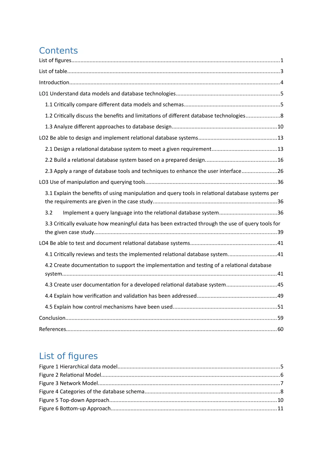
Contents
List of figures.........................................................................................................................................1
List of table............................................................................................................................................3
Introduction...........................................................................................................................................4
LO1 Understand data models and database technologies....................................................................5
1.1 Critically compare different data models and schemas...............................................................5
1.2 Critically discuss the benefits and limitations of different database technologies......................8
1.3 Analyze different approaches to database design.....................................................................10
LO2 Be able to design and implement relational database systems....................................................13
2.1 Design a relational database system to meet a given requirement...........................................13
2.2 Build a relational database system based on a prepared design...............................................16
2.3 Apply a range of database tools and techniques to enhance the user interface.......................26
LO3 Use of manipulation and querying tools......................................................................................36
3.1 Explain the benefits of using manipulation and query tools in relational database systems per
the requirements are given in the case study..................................................................................36
3.2 Implement a query language into the relational database system......................................36
3.3 Critically evaluate how meaningful data has been extracted through the use of query tools for
the given case study........................................................................................................................39
LO4 Be able to test and document relational database systems.........................................................41
4.1 Critically reviews and tests the implemented relational database system................................41
4.2 Create documentation to support the implementation and testing of a relational database
system.............................................................................................................................................41
4.3 Create user documentation for a developed relational database system.................................45
4.4 Explain how verification and validation has been addressed.....................................................49
4.5 Explain how control mechanisms have been used....................................................................51
Conclusion...........................................................................................................................................59
References...........................................................................................................................................60
List of figures
Figure 1 Hierarchical data model...........................................................................................................5
Figure 2 Relational Model......................................................................................................................6
Figure 3 Network Model........................................................................................................................7
Figure 4 Categories of the database schema.........................................................................................8
Figure 5 Top-down Approach..............................................................................................................10
Figure 6 Bottom-up Approach.............................................................................................................11
Secure Best Marks with AI Grader
Need help grading? Try our AI Grader for instant feedback on your assignments.
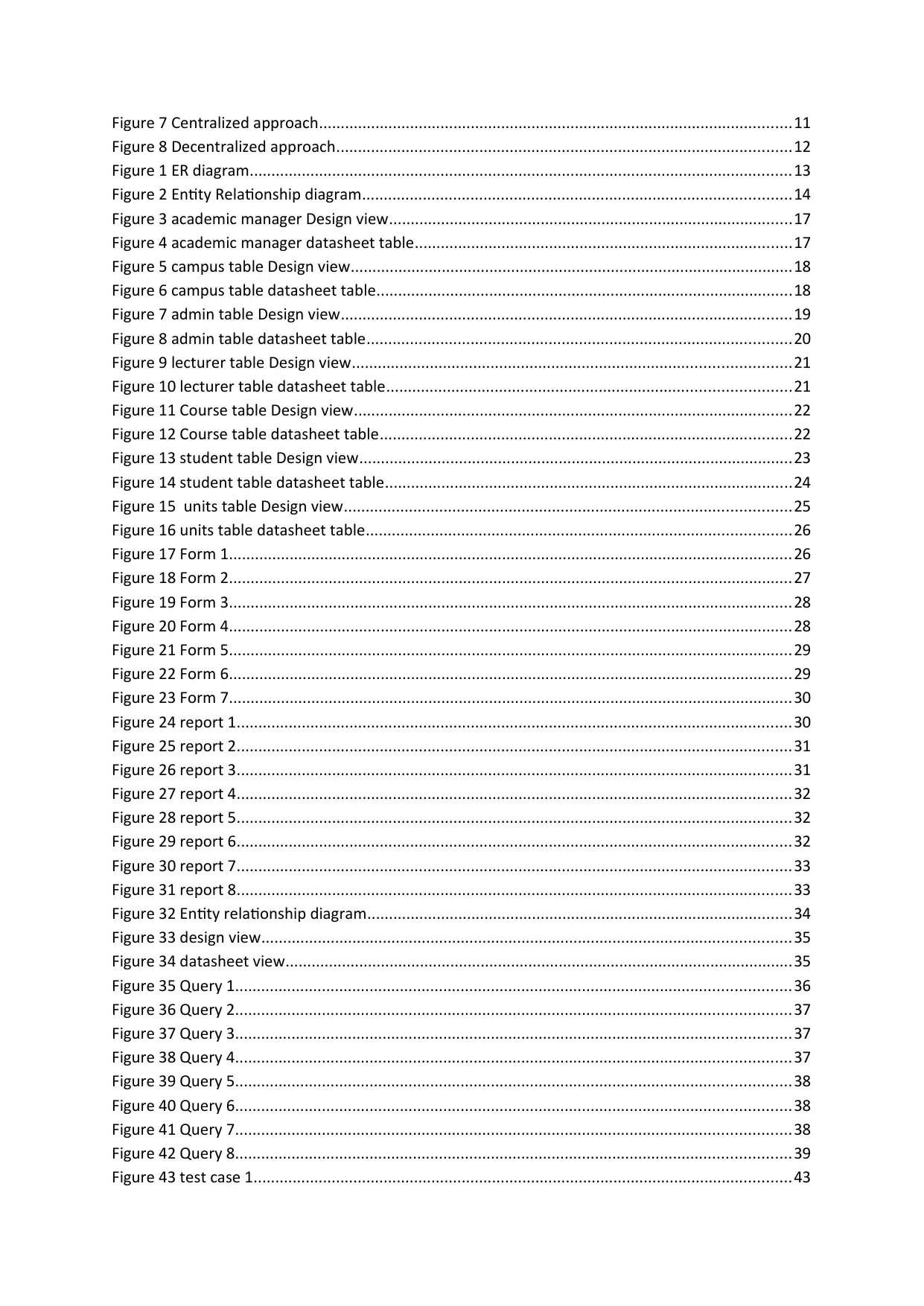
Figure 7 Centralized approach.............................................................................................................11
Figure 8 Decentralized approach.........................................................................................................12
Figure 1 ER diagram.............................................................................................................................13
Figure 2 Entity Relationship diagram...................................................................................................14
Figure 3 academic manager Design view.............................................................................................17
Figure 4 academic manager datasheet table.......................................................................................17
Figure 5 campus table Design view......................................................................................................18
Figure 6 campus table datasheet table................................................................................................18
Figure 7 admin table Design view........................................................................................................19
Figure 8 admin table datasheet table..................................................................................................20
Figure 9 lecturer table Design view.....................................................................................................21
Figure 10 lecturer table datasheet table.............................................................................................21
Figure 11 Course table Design view.....................................................................................................22
Figure 12 Course table datasheet table...............................................................................................22
Figure 13 student table Design view....................................................................................................23
Figure 14 student table datasheet table..............................................................................................24
Figure 15 units table Design view.......................................................................................................25
Figure 16 units table datasheet table..................................................................................................26
Figure 17 Form 1..................................................................................................................................26
Figure 18 Form 2..................................................................................................................................27
Figure 19 Form 3..................................................................................................................................28
Figure 20 Form 4..................................................................................................................................28
Figure 21 Form 5..................................................................................................................................29
Figure 22 Form 6..................................................................................................................................29
Figure 23 Form 7..................................................................................................................................30
Figure 24 report 1................................................................................................................................30
Figure 25 report 2................................................................................................................................31
Figure 26 report 3................................................................................................................................31
Figure 27 report 4................................................................................................................................32
Figure 28 report 5................................................................................................................................32
Figure 29 report 6................................................................................................................................32
Figure 30 report 7................................................................................................................................33
Figure 31 report 8................................................................................................................................33
Figure 32 Entity relationship diagram..................................................................................................34
Figure 33 design view..........................................................................................................................35
Figure 34 datasheet view.....................................................................................................................35
Figure 35 Query 1................................................................................................................................36
Figure 36 Query 2................................................................................................................................37
Figure 37 Query 3................................................................................................................................37
Figure 38 Query 4................................................................................................................................37
Figure 39 Query 5................................................................................................................................38
Figure 40 Query 6................................................................................................................................38
Figure 41 Query 7................................................................................................................................38
Figure 42 Query 8................................................................................................................................39
Figure 43 test case 1............................................................................................................................43
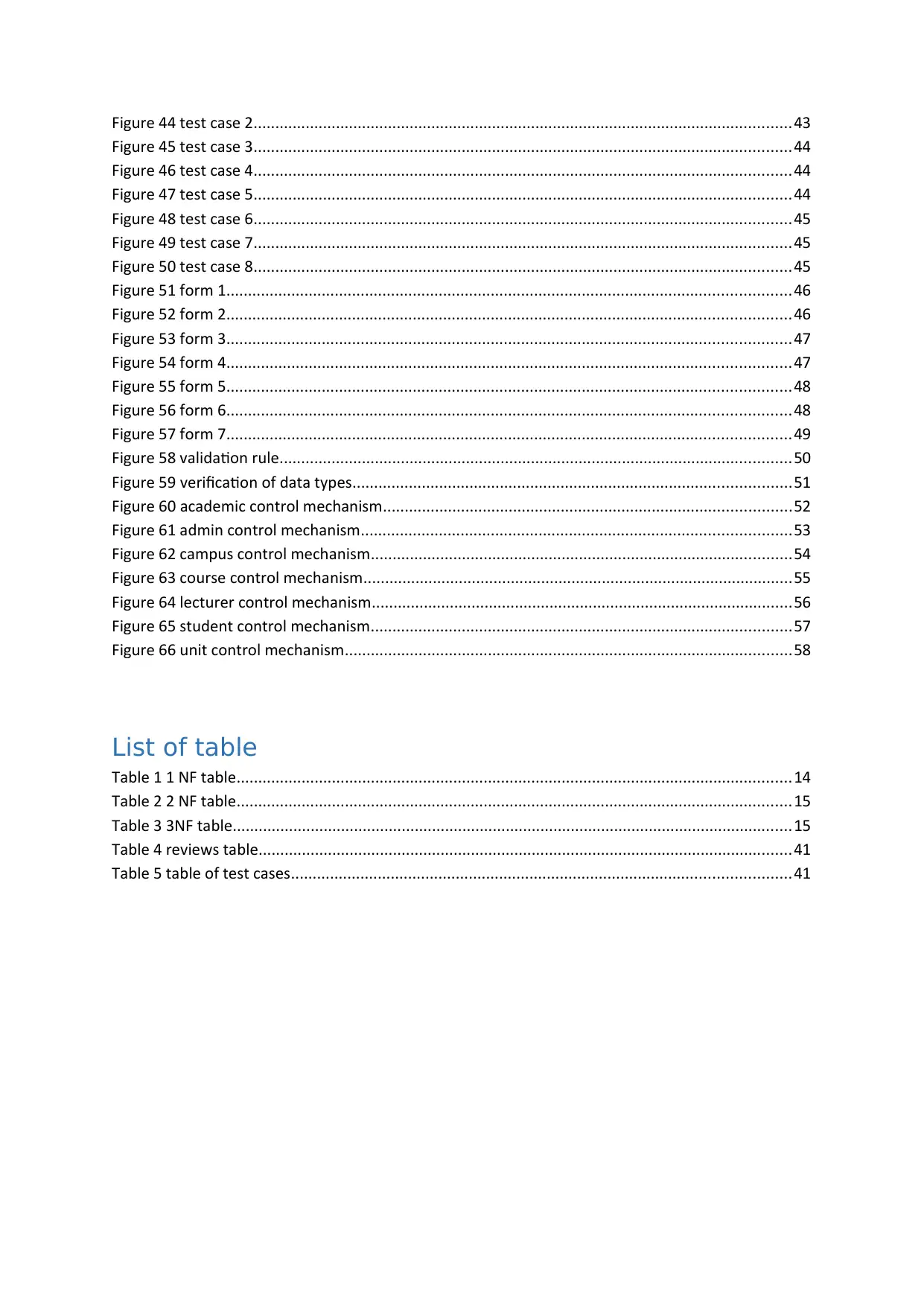
Figure 44 test case 2............................................................................................................................43
Figure 45 test case 3............................................................................................................................44
Figure 46 test case 4............................................................................................................................44
Figure 47 test case 5............................................................................................................................44
Figure 48 test case 6............................................................................................................................45
Figure 49 test case 7............................................................................................................................45
Figure 50 test case 8............................................................................................................................45
Figure 51 form 1..................................................................................................................................46
Figure 52 form 2..................................................................................................................................46
Figure 53 form 3..................................................................................................................................47
Figure 54 form 4..................................................................................................................................47
Figure 55 form 5..................................................................................................................................48
Figure 56 form 6..................................................................................................................................48
Figure 57 form 7..................................................................................................................................49
Figure 58 validation rule......................................................................................................................50
Figure 59 verification of data types.....................................................................................................51
Figure 60 academic control mechanism..............................................................................................52
Figure 61 admin control mechanism...................................................................................................53
Figure 62 campus control mechanism.................................................................................................54
Figure 63 course control mechanism...................................................................................................55
Figure 64 lecturer control mechanism.................................................................................................56
Figure 65 student control mechanism.................................................................................................57
Figure 66 unit control mechanism.......................................................................................................58
List of table
Table 1 1 NF table................................................................................................................................14
Table 2 2 NF table................................................................................................................................15
Table 3 3NF table.................................................................................................................................15
Table 4 reviews table...........................................................................................................................41
Table 5 table of test cases...................................................................................................................41

Introduction
This report is developed for Dominican college who wants to provide a database to the user in which
they can store information of college members, students, course, lecturer, units and more. This
database system is designed in such way that it fulfills the requirement of Dominican College and
provides a fully functional system to store information. The report determines various database
technologies and entity relationship diagram which give an idea to design database. The testing will
be provided to validate and ensure the quality of database design. The user documentation explains
the forms and their use by showing screen captures. The report is prepared on database design
which describes SQL queries, forms, ER diagrams to help in providing an understanding of this
system in a proper manner.
Secure Best Marks with AI Grader
Need help grading? Try our AI Grader for instant feedback on your assignments.
LO1 Understand data models and database
technologies
1.1 Critically compare different data models and schemas
Database Model: This shows the logical structure of a database in addition to constraints and
relationships enabling how the data is going to be accessed and stored. The relationship within the
database depicts how the data is retrieved and stored. It is a kind of data model which explains how
data is going to be organized, manipulated and stored. Database model has been categorized in
following types:
Hierarchical data model:
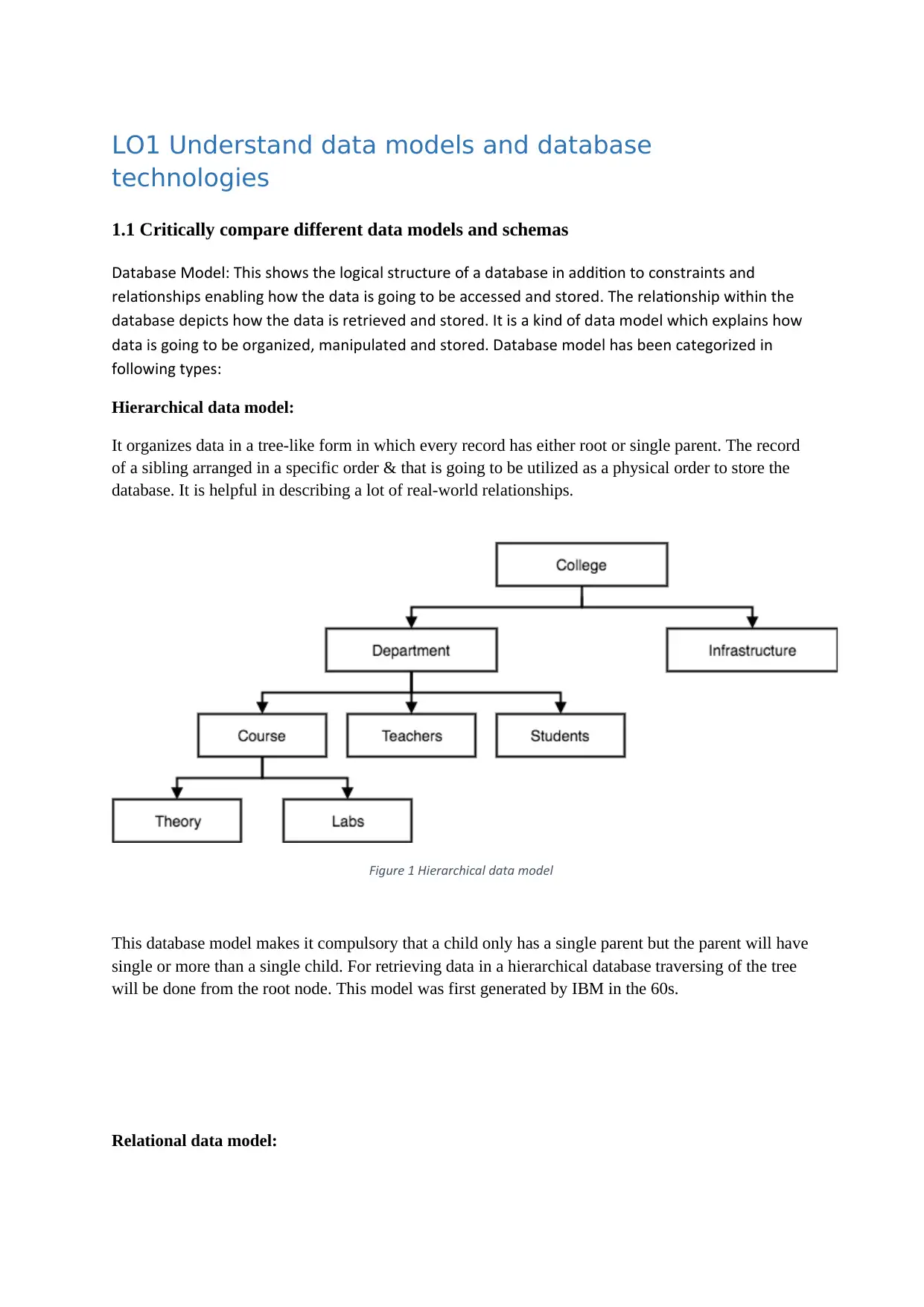
It organizes data in a tree-like form in which every record has either root or single parent. The record
of a sibling arranged in a specific order & that is going to be utilized as a physical order to store the
database. It is helpful in describing a lot of real-world relationships.
Figure 1 Hierarchical data model
This database model makes it compulsory that a child only has a single parent but the parent will have
single or more than a single child. For retrieving data in a hierarchical database traversing of the tree
will be done from the root node. This model was first generated by IBM in the 60s.
Relational data model:
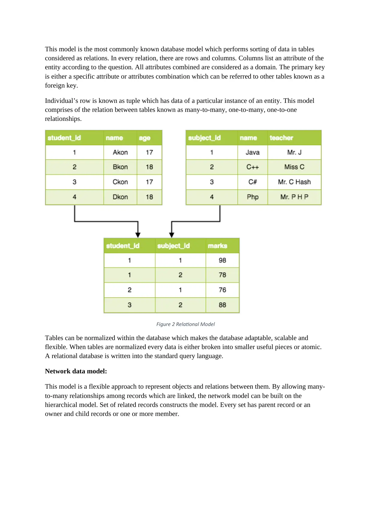
This model is the most commonly known database model which performs sorting of data in tables
considered as relations. In every relation, there are rows and columns. Columns list an attribute of the
entity according to the question. All attributes combined are considered as a domain. The primary key
is either a specific attribute or attributes combination which can be referred to other tables known as a
foreign key.
Individual’s row is known as tuple which has data of a particular instance of an entity. This model
comprises of the relation between tables known as many-to-many, one-to-many, one-to-one
relationships.
Figure 2 Relational Model
Tables can be normalized within the database which makes the database adaptable, scalable and
flexible. When tables are normalized every data is either broken into smaller useful pieces or atomic.
A relational database is written into the standard query language.
Network data model:
This model is a flexible approach to represent objects and relations between them. By allowing many-
to-many relationships among records which are linked, the network model can be built on the
hierarchical model. Set of related records constructs the model. Every set has parent record or an
owner and child records or one or more member.
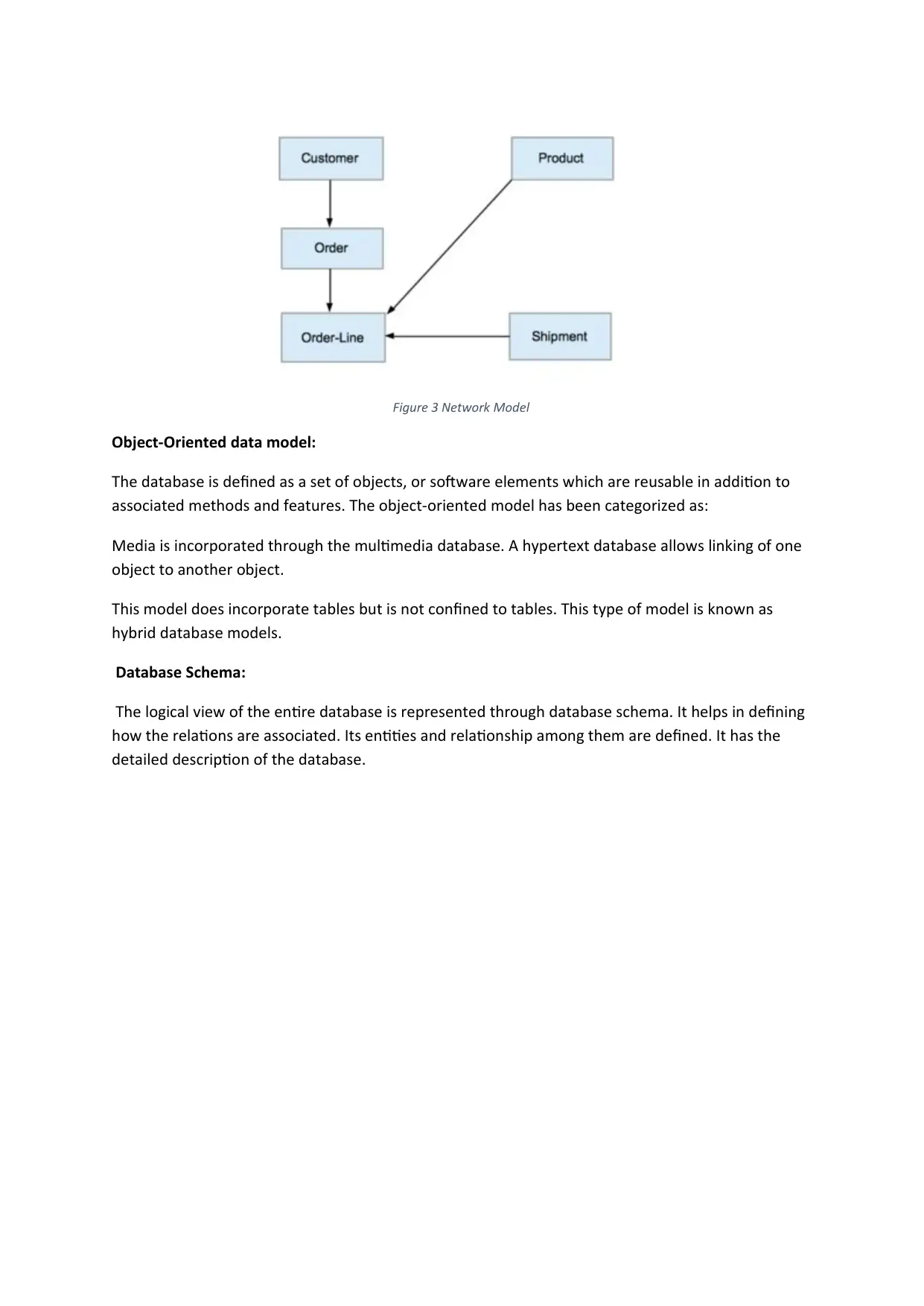
Figure 3 Network Model
Object-Oriented data model:
The database is defined as a set of objects, or software elements which are reusable in addition to
associated methods and features. The object-oriented model has been categorized as:
Media is incorporated through the multimedia database. A hypertext database allows linking of one
object to another object.
This model does incorporate tables but is not confined to tables. This type of model is known as
hybrid database models.
Database Schema:
The logical view of the entire database is represented through database schema. It helps in defining
how the relations are associated. Its entities and relationship among them are defined. It has the
detailed description of the database.
Paraphrase This Document
Need a fresh take? Get an instant paraphrase of this document with our AI Paraphraser
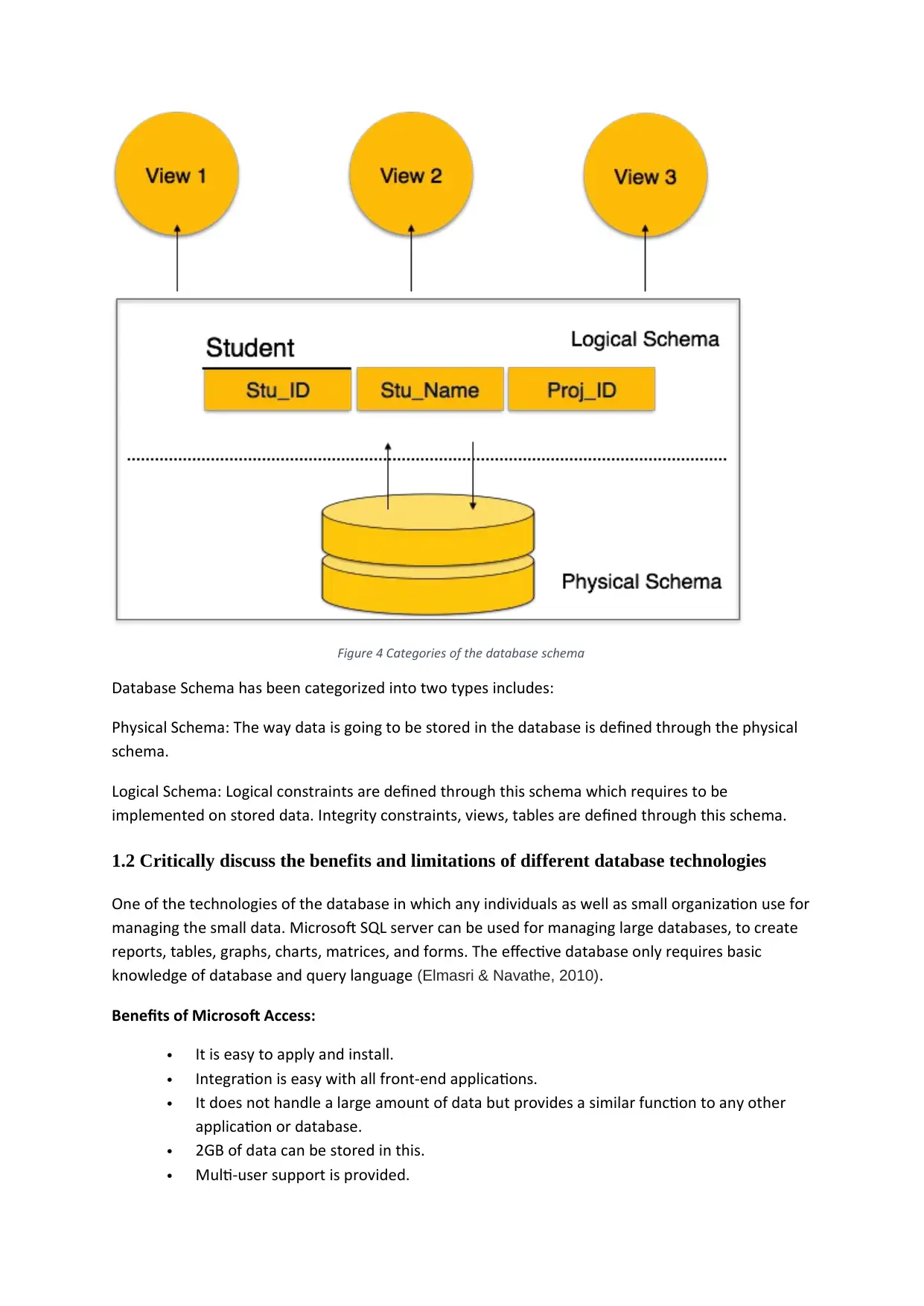
Figure 4 Categories of the database schema
Database Schema has been categorized into two types includes:
Physical Schema: The way data is going to be stored in the database is defined through the physical
schema.
Logical Schema: Logical constraints are defined through this schema which requires to be
implemented on stored data. Integrity constraints, views, tables are defined through this schema.
1.2 Critically discuss the benefits and limitations of different database technologies
One of the technologies of the database in which any individuals as well as small organization use for
managing the small data. Microsoft SQL server can be used for managing large databases, to create
reports, tables, graphs, charts, matrices, and forms. The effective database only requires basic
knowledge of database and query language (Elmasri & Navathe, 2010).
Benefits of Microsoft Access:
It is easy to apply and install.
Integration is easy with all front-end applications.
It does not handle a large amount of data but provides a similar function to any other
application or database.
2GB of data can be stored in this.
Multi-user support is provided.
Data importing is easy.
Limitations of MS access:
It will only be helpful for small organization as it cannot store data beyond 2GB.
It limits the access speed of database since it stores the data into a single file.
Not more than 10 users in a database can use the database concurrently.
Benefits of Oracle:
A large database is supported.
Triggers and cursors are used for easy programming.
Database of any number of records and size can be handled.
Limitations of Oracle:
Not useful for the small organization since it handles only large database.
Very costly.
Benefits of SQL:
Manages relational databases.
Easy to understand and learn.
Flexible
Security Mechanism is robust
Reliable
Works on client-server architecture
Supports object-based programming
1.3 Analyze different approaches to database design
Different approaches to design database are categorized as:
Top-Down Approach:
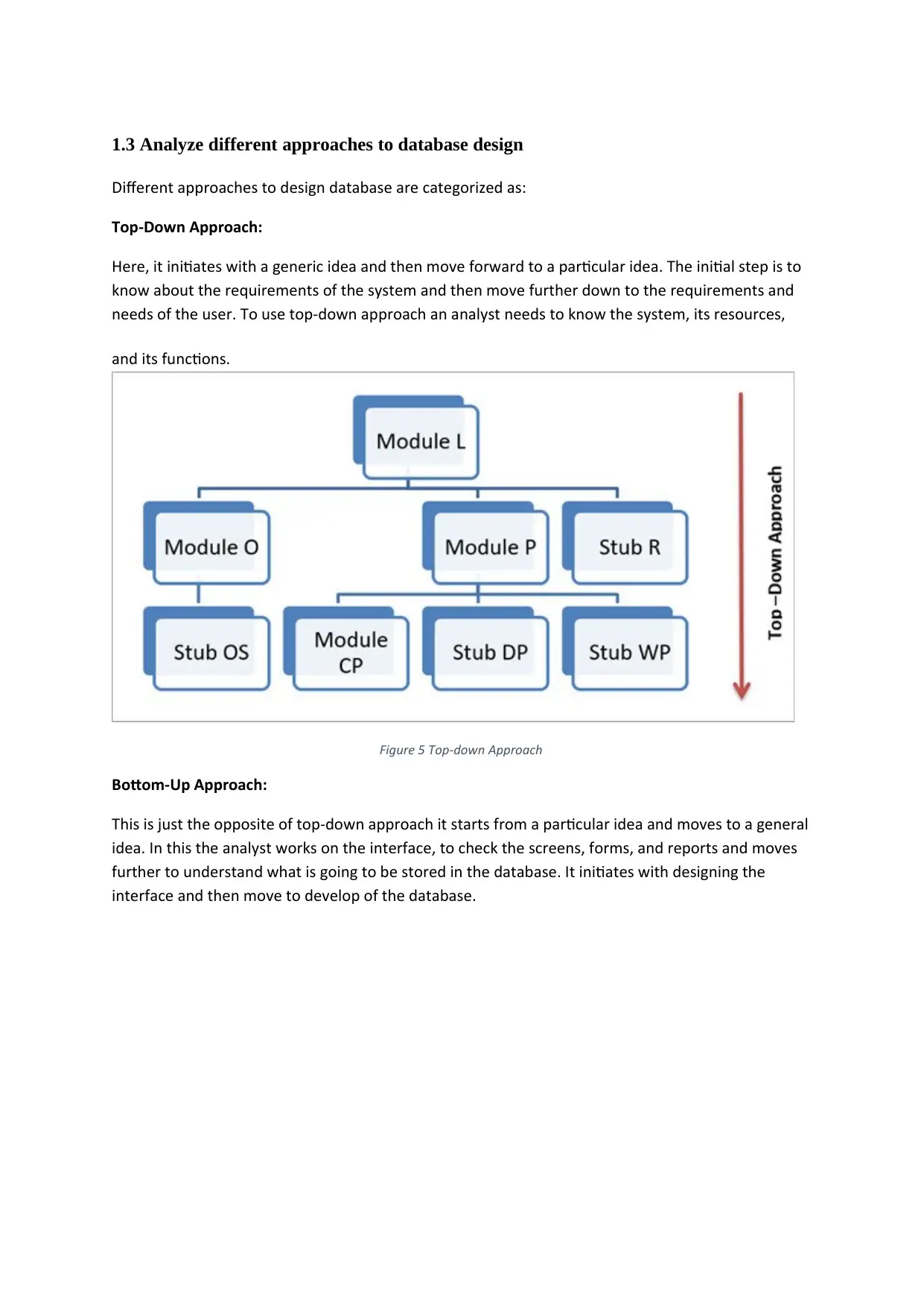
Here, it initiates with a generic idea and then move forward to a particular idea. The initial step is to
know about the requirements of the system and then move further down to the requirements and
needs of the user. To use top-down approach an analyst needs to know the system, its resources,
and its functions.
Figure 5 Top-down Approach
Bottom-Up Approach:
This is just the opposite of top-down approach it starts from a particular idea and moves to a general
idea. In this the analyst works on the interface, to check the screens, forms, and reports and moves
further to understand what is going to be stored in the database. It initiates with designing the
interface and then move to develop of the database.
Secure Best Marks with AI Grader
Need help grading? Try our AI Grader for instant feedback on your assignments.
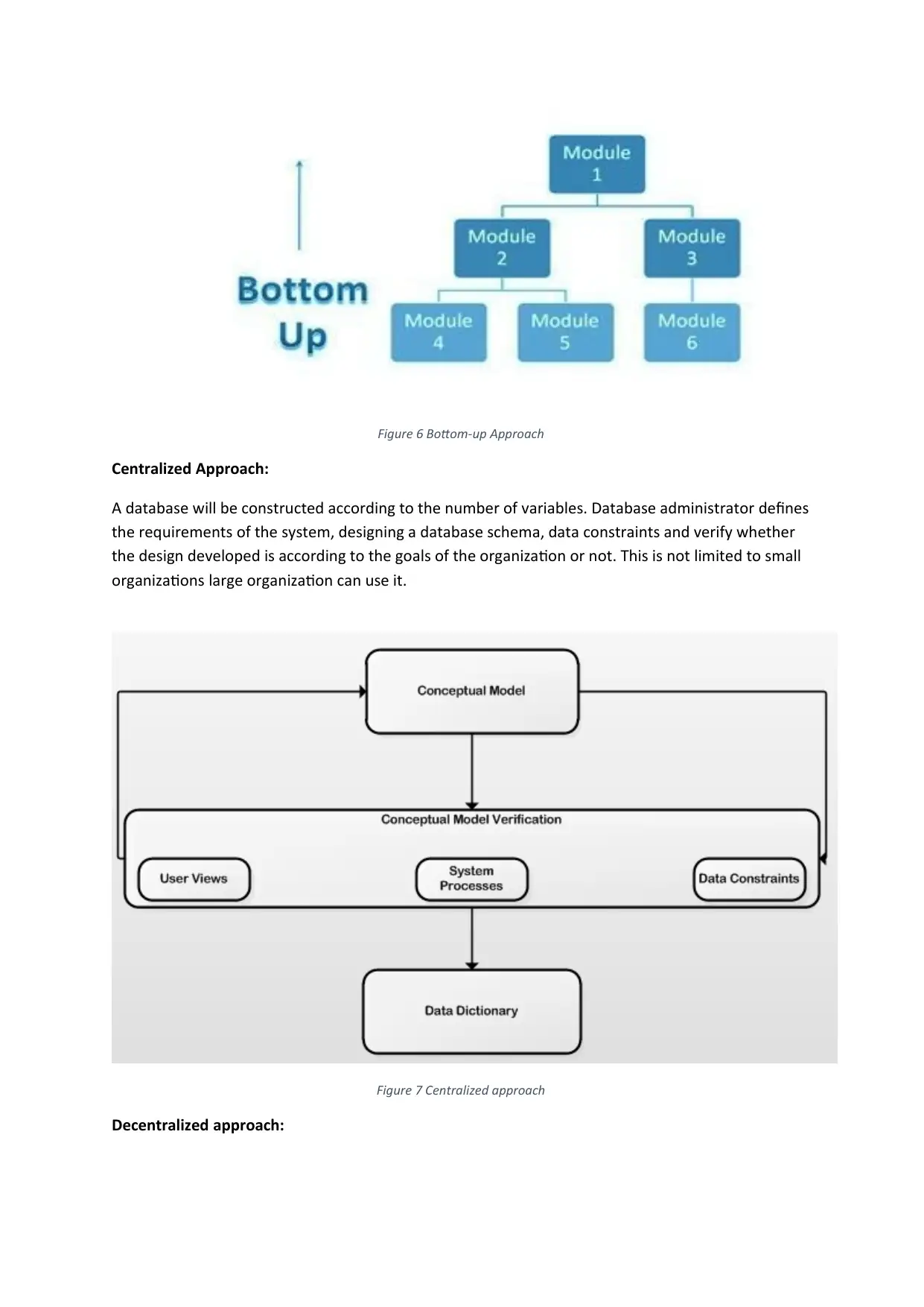
Figure 6 Bottom-up Approach
Centralized Approach:
A database will be constructed according to the number of variables. Database administrator defines
the requirements of the system, designing a database schema, data constraints and verify whether
the design developed is according to the goals of the organization or not. This is not limited to small
organizations large organization can use it.
Figure 7 Centralized approach
Decentralized approach:
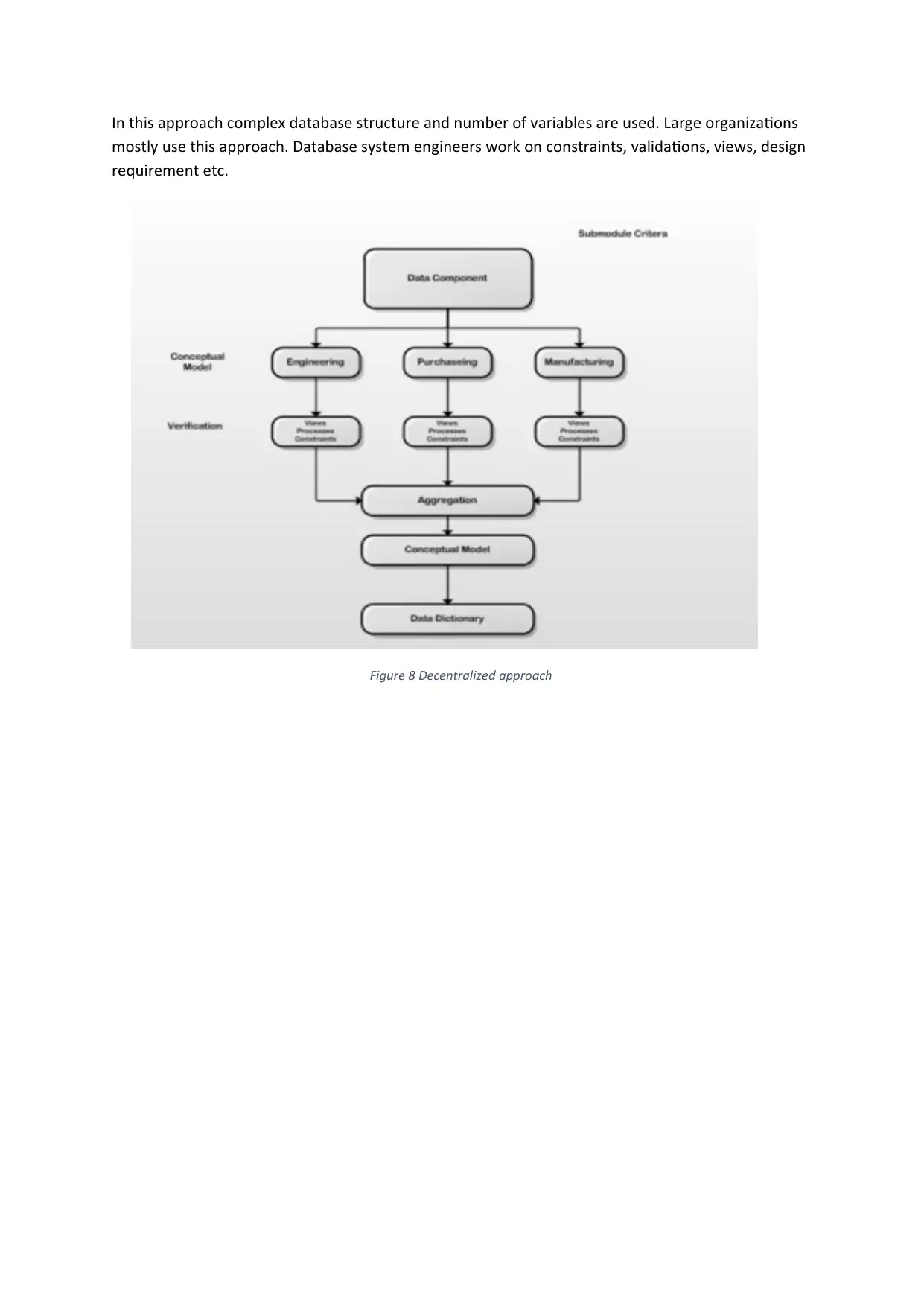
In this approach complex database structure and number of variables are used. Large organizations
mostly use this approach. Database system engineers work on constraints, validations, views, design
requirement etc.
Figure 8 Decentralized approach
mostly use this approach. Database system engineers work on constraints, validations, views, design
requirement etc.
Figure 8 Decentralized approach
LO2 Be able to design and implement relational
database systems
2.1 Design a relational database system to meet a given requirement
ERD Model:
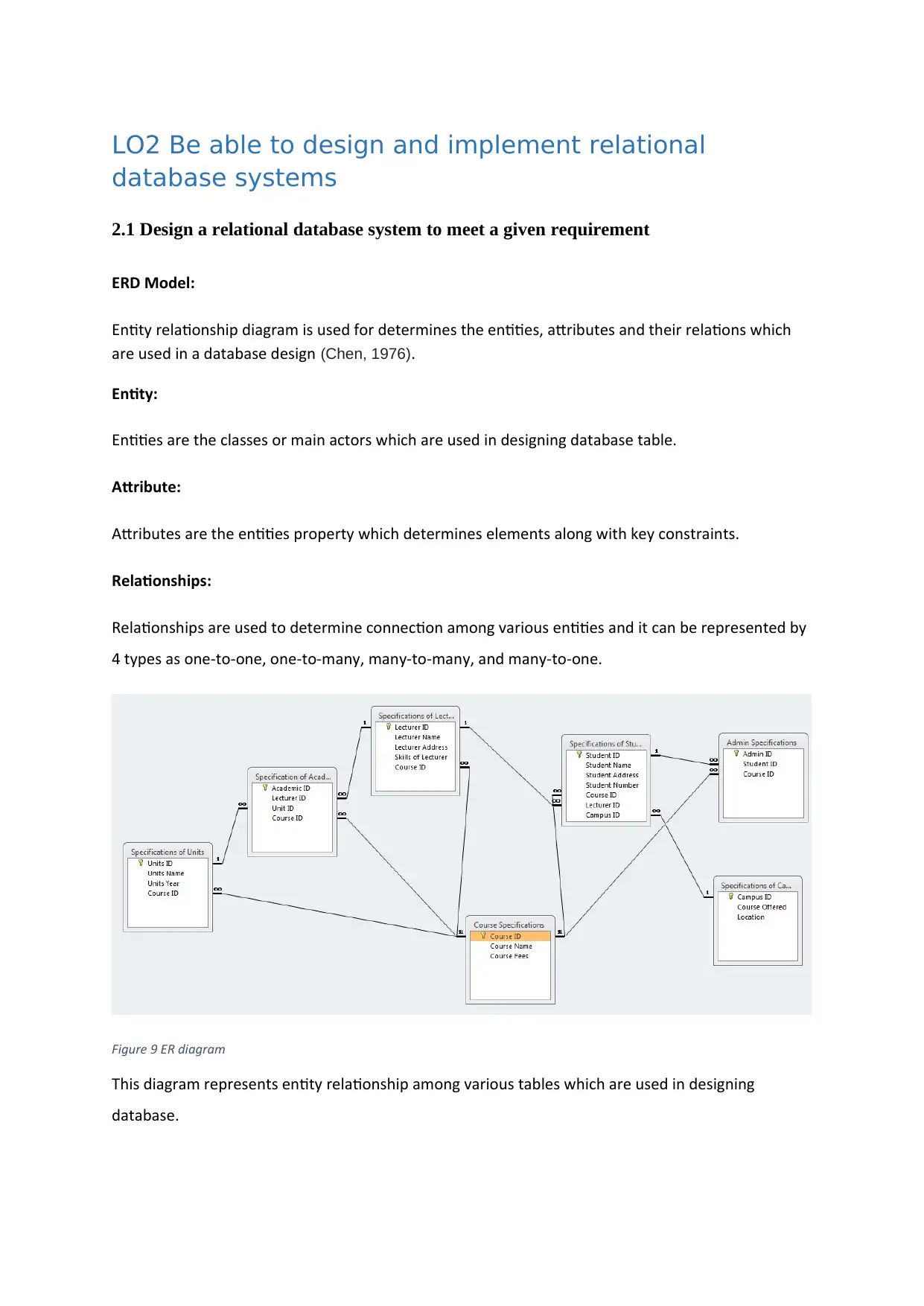
Entity relationship diagram is used for determines the entities, attributes and their relations which
are used in a database design (Chen, 1976).
Entity:
Entities are the classes or main actors which are used in designing database table.
Attribute:
Attributes are the entities property which determines elements along with key constraints.
Relationships:
Relationships are used to determine connection among various entities and it can be represented by
4 types as one-to-one, one-to-many, many-to-many, and many-to-one.
Figure 9 ER diagram
This diagram represents entity relationship among various tables which are used in designing
database.
Paraphrase This Document
Need a fresh take? Get an instant paraphrase of this document with our AI Paraphraser
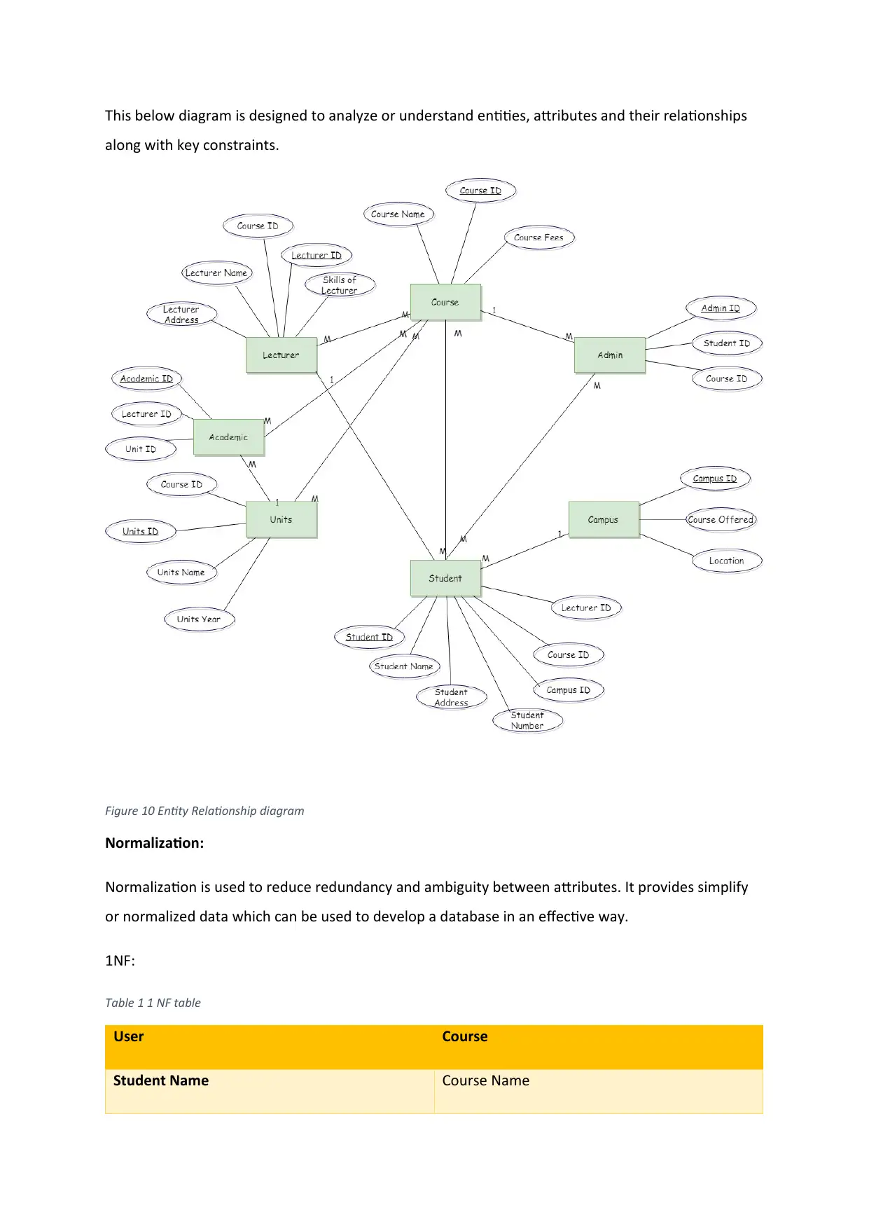
This below diagram is designed to analyze or understand entities, attributes and their relationships
along with key constraints.
Figure 10 Entity Relationship diagram
Normalization:
Normalization is used to reduce redundancy and ambiguity between attributes. It provides simplify
or normalized data which can be used to develop a database in an effective way.
1NF:
Table 1 1 NF table
User Course
Student Name Course Name
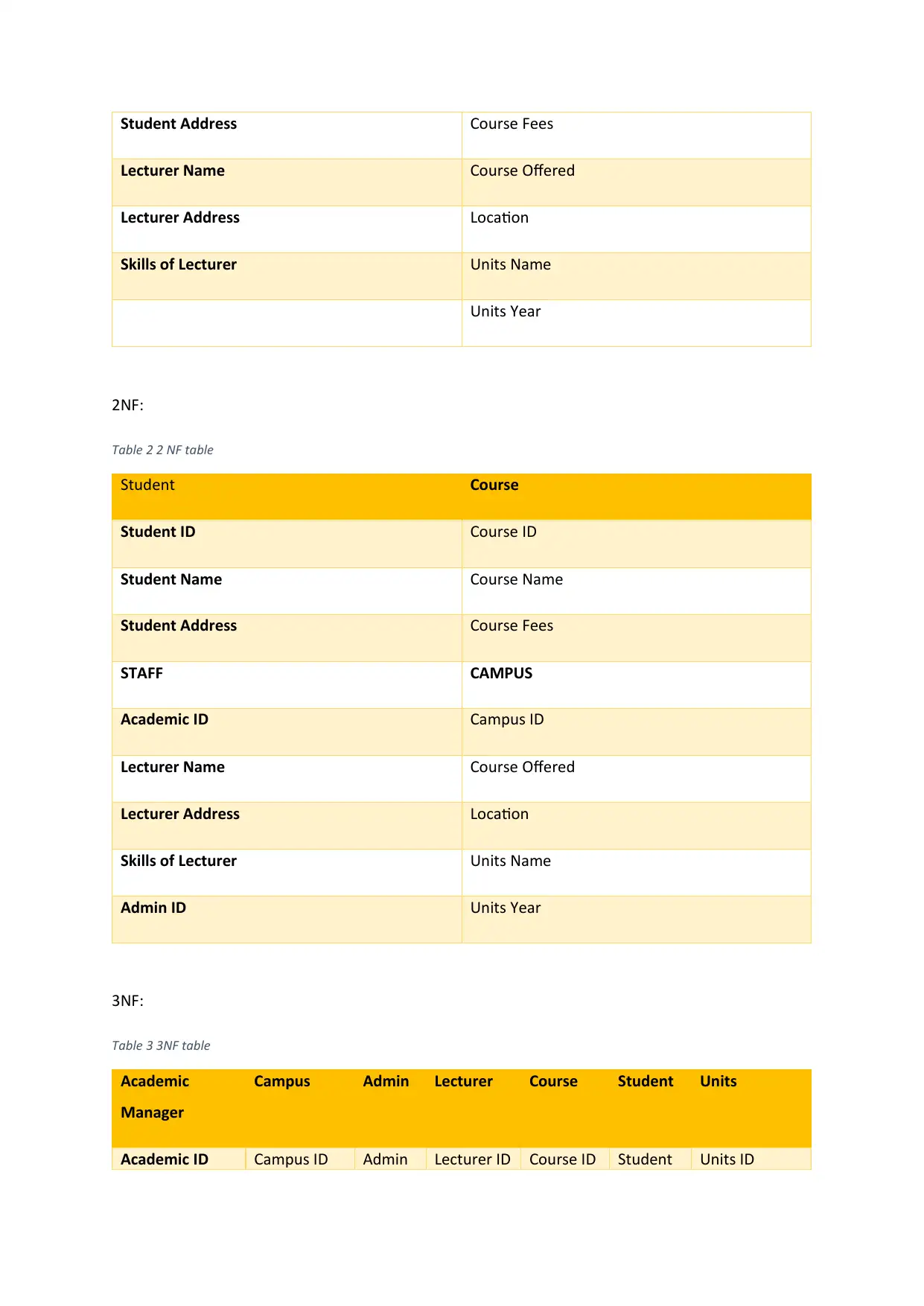
Student Address Course Fees
Lecturer Name Course Offered
Lecturer Address Location
Skills of Lecturer Units Name
Units Year
2NF:
Table 2 2 NF table
Student Course
Student ID Course ID
Student Name Course Name
Student Address Course Fees
STAFF CAMPUS
Academic ID Campus ID
Lecturer Name Course Offered
Lecturer Address Location
Skills of Lecturer Units Name
Admin ID Units Year
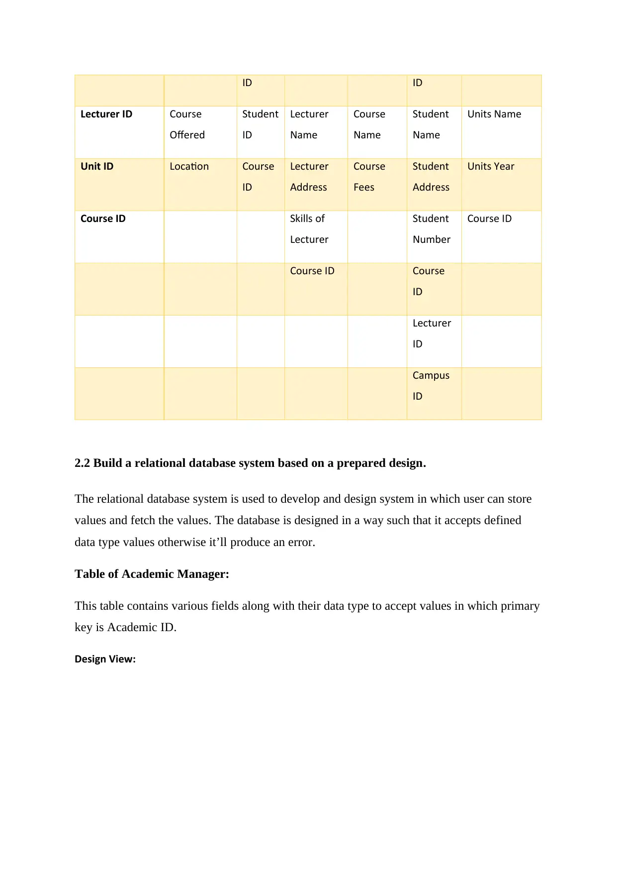
3NF:
Table 3 3NF table
Academic
Manager
Campus Admin Lecturer Course Student Units
Academic ID Campus ID Admin Lecturer ID Course ID Student Units ID
Lecturer Name Course Offered
Lecturer Address Location
Skills of Lecturer Units Name
Units Year
2NF:
Table 2 2 NF table
Student Course
Student ID Course ID
Student Name Course Name
Student Address Course Fees
STAFF CAMPUS
Academic ID Campus ID
Lecturer Name Course Offered
Lecturer Address Location
Skills of Lecturer Units Name
Admin ID Units Year
3NF:
Table 3 3NF table
Academic
Manager
Campus Admin Lecturer Course Student Units
Academic ID Campus ID Admin Lecturer ID Course ID Student Units ID
ID ID
Lecturer ID Course
Offered
Student
ID
Lecturer
Name
Course
Name
Student
Name
Units Name
Unit ID Location Course
ID
Lecturer
Address
Course
Fees
Student
Address
Units Year
Course ID Skills of
Lecturer
Student
Number
Course ID
Course ID Course
ID
Lecturer
ID
Campus
ID
2.2 Build a relational database system based on a prepared design.
The relational database system is used to develop and design system in which user can store
values and fetch the values. The database is designed in a way such that it accepts defined
data type values otherwise it’ll produce an error.
Table of Academic Manager:
This table contains various fields along with their data type to accept values in which primary
key is Academic ID.
Design View:
Secure Best Marks with AI Grader
Need help grading? Try our AI Grader for instant feedback on your assignments.
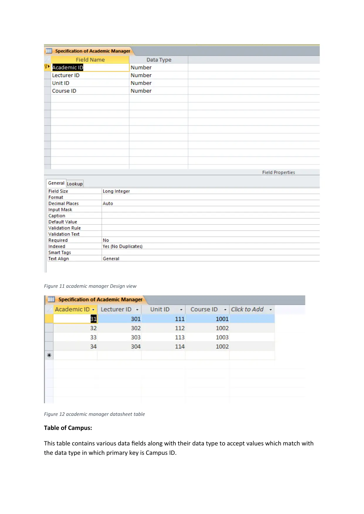
Figure 11 academic manager Design view
Figure 12 academic manager datasheet table
Table of Campus:
This table contains various data fields along with their data type to accept values which match with
the data type in which primary key is Campus ID.
Figure 12 academic manager datasheet table
Table of Campus:
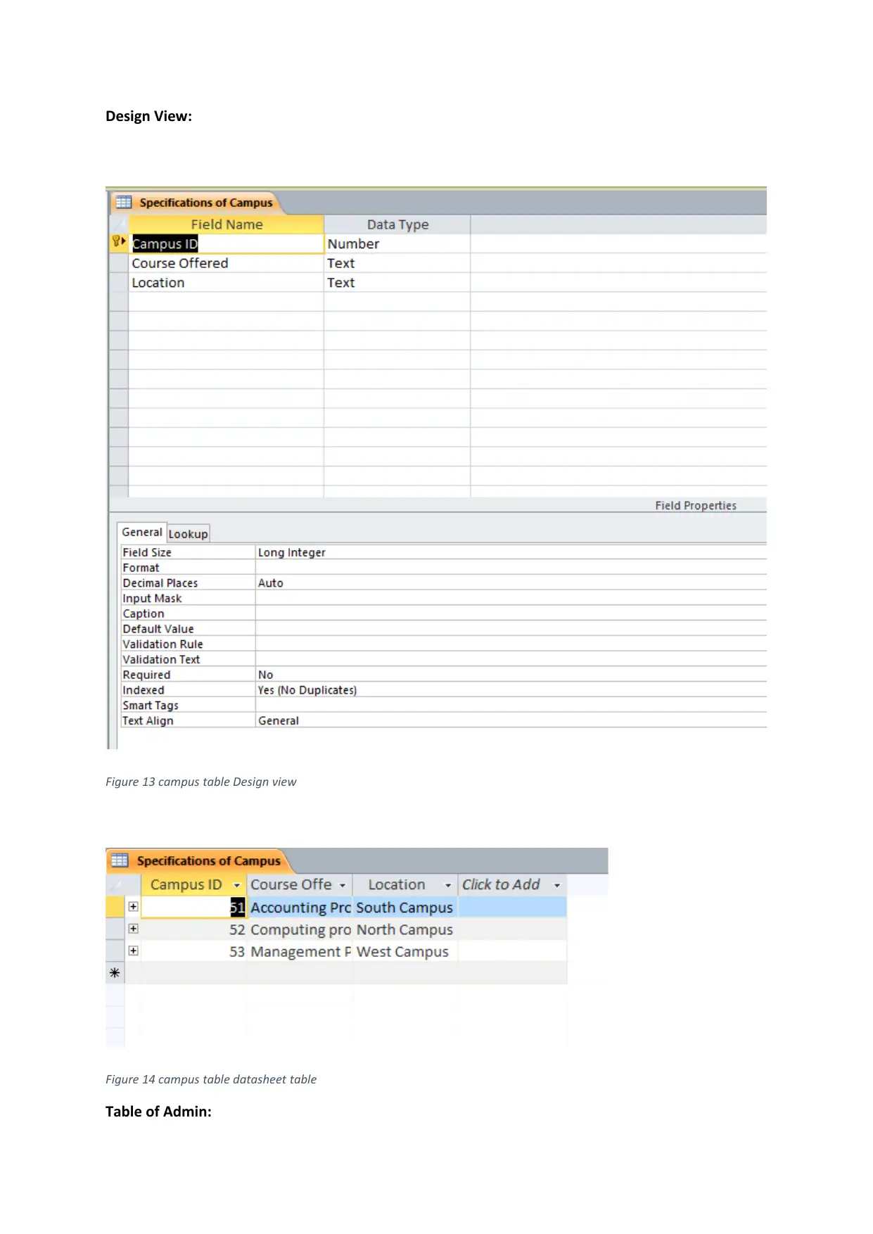
This table contains various data fields along with their data type to accept values which match with
the data type in which primary key is Campus ID.
Design View:
Figure 13 campus table Design view
Figure 14 campus table datasheet table
Table of Admin:
Figure 13 campus table Design view
Figure 14 campus table datasheet table
Table of Admin:
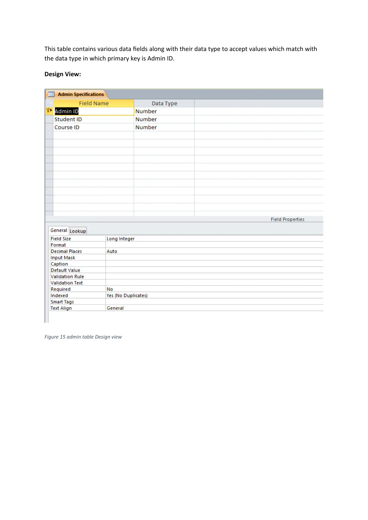
This table contains various data fields along with their data type to accept values which match with
the data type in which primary key is Admin ID.
Design View:
Figure 15 admin table Design view
the data type in which primary key is Admin ID.
Design View:
Figure 15 admin table Design view
Paraphrase This Document
Need a fresh take? Get an instant paraphrase of this document with our AI Paraphraser
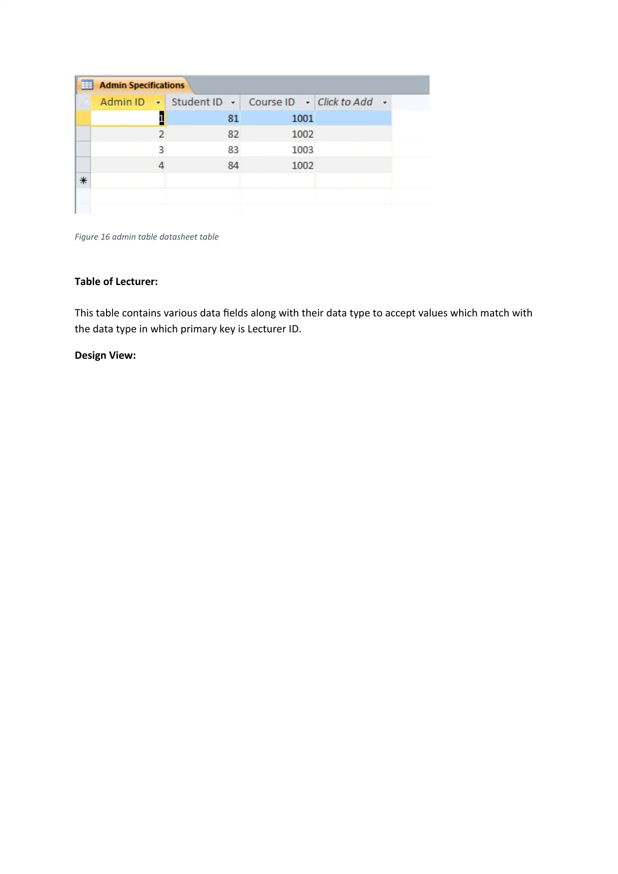
Figure 16 admin table datasheet table
Table of Lecturer:
This table contains various data fields along with their data type to accept values which match with
the data type in which primary key is Lecturer ID.
Design View:
Table of Lecturer:
This table contains various data fields along with their data type to accept values which match with
the data type in which primary key is Lecturer ID.
Design View:
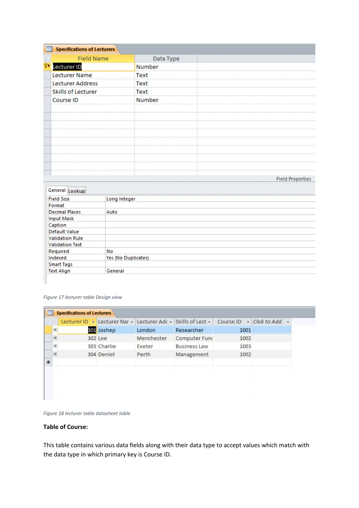
Figure 17 lecturer table Design view
Figure 18 lecturer table datasheet table
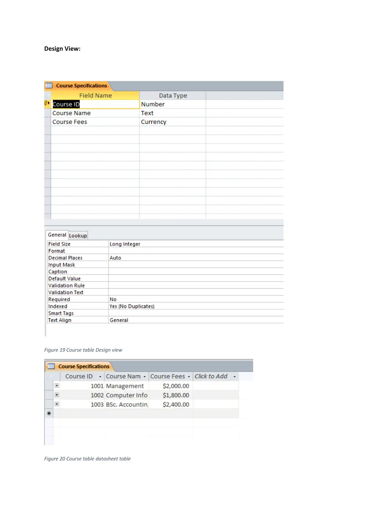
Table of Course:
This table contains various data fields along with their data type to accept values which match with
the data type in which primary key is Course ID.
Figure 18 lecturer table datasheet table
Table of Course:
This table contains various data fields along with their data type to accept values which match with
the data type in which primary key is Course ID.
Design View:
Figure 19 Course table Design view
Figure 20 Course table datasheet table
Figure 19 Course table Design view
Figure 20 Course table datasheet table
Secure Best Marks with AI Grader
Need help grading? Try our AI Grader for instant feedback on your assignments.
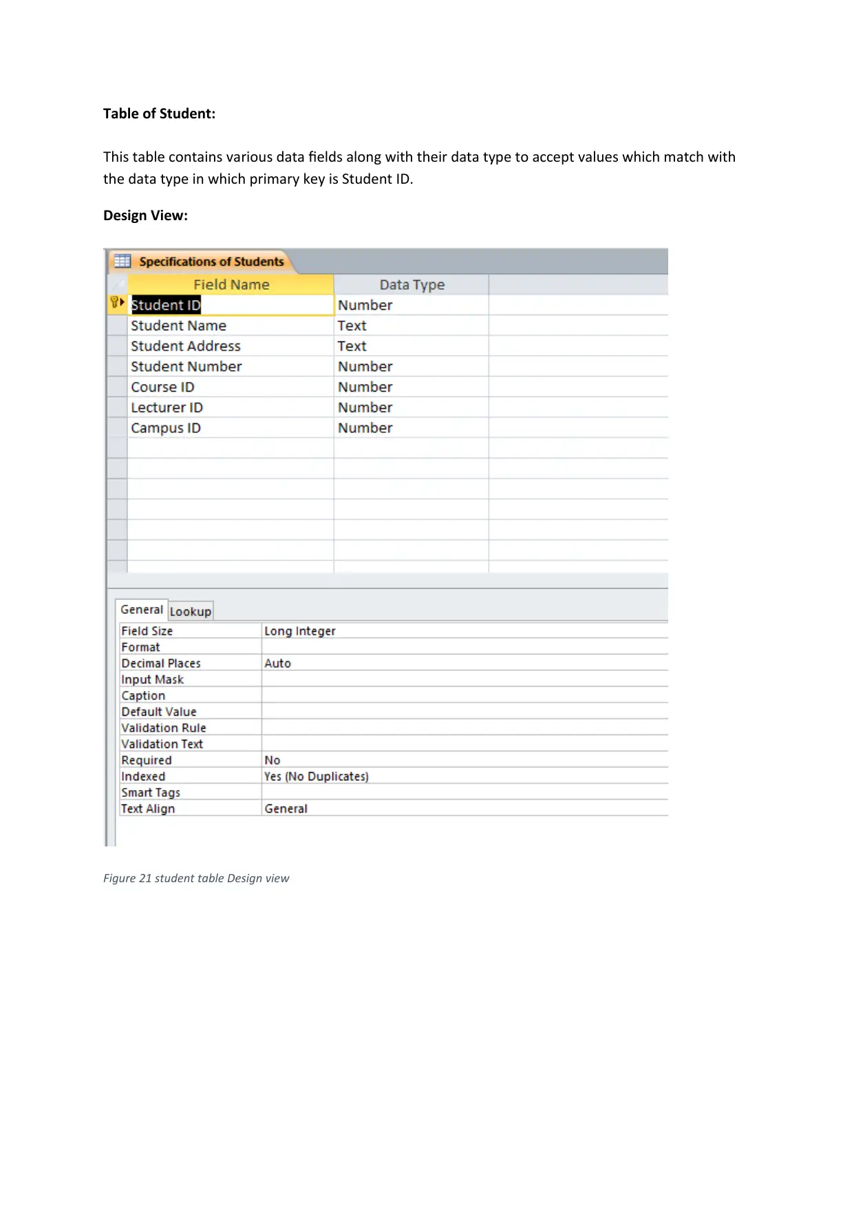
Table of Student:
This table contains various data fields along with their data type to accept values which match with
the data type in which primary key is Student ID.
Design View:
Figure 21 student table Design view
This table contains various data fields along with their data type to accept values which match with
the data type in which primary key is Student ID.
Design View:
Figure 21 student table Design view
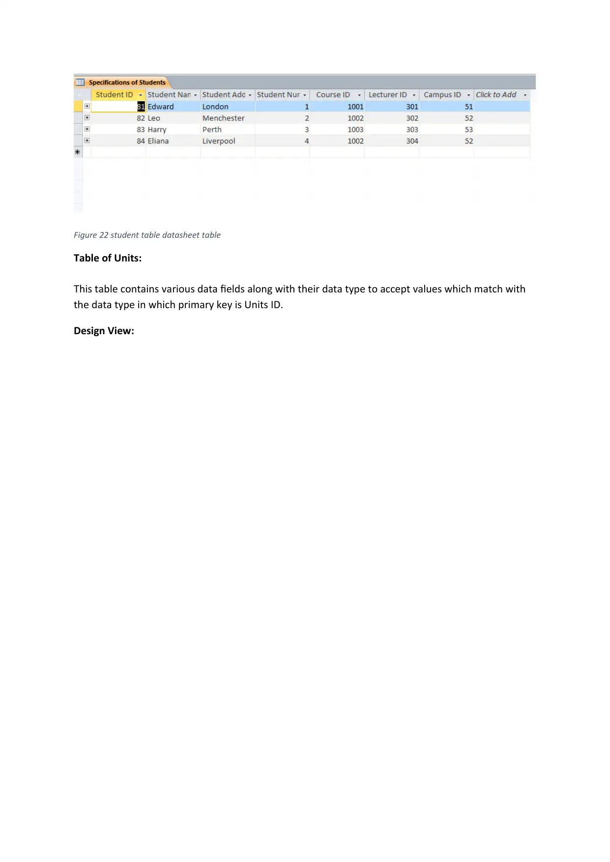
Figure 22 student table datasheet table
Table of Units:
This table contains various data fields along with their data type to accept values which match with
the data type in which primary key is Units ID.
Design View:
Table of Units:
This table contains various data fields along with their data type to accept values which match with
the data type in which primary key is Units ID.
Design View:
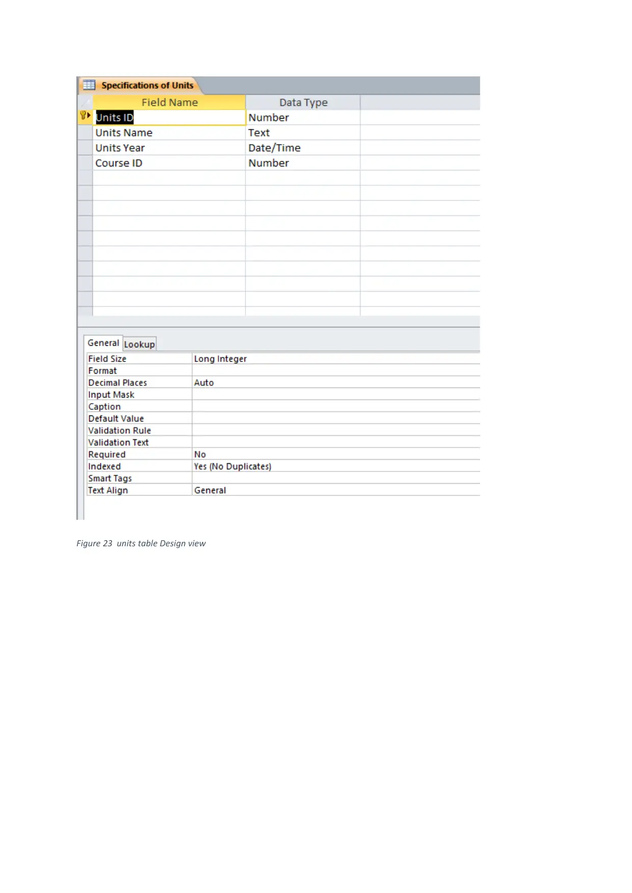
Figure 23 units table Design view
Paraphrase This Document
Need a fresh take? Get an instant paraphrase of this document with our AI Paraphraser
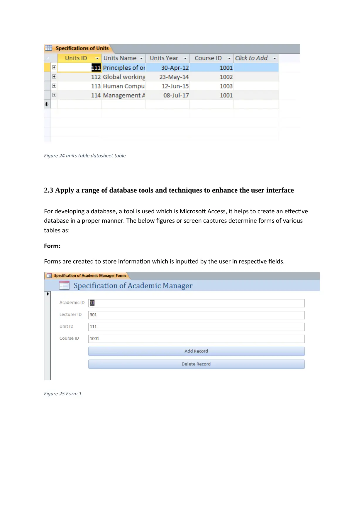
Figure 24 units table datasheet table
2.3 Apply a range of database tools and techniques to enhance the user interface
For developing a database, a tool is used which is Microsoft Access, it helps to create an effective
database in a proper manner. The below figures or screen captures determine forms of various
tables as:
Form:
Forms are created to store information which is inputted by the user in respective fields.
Figure 25 Form 1
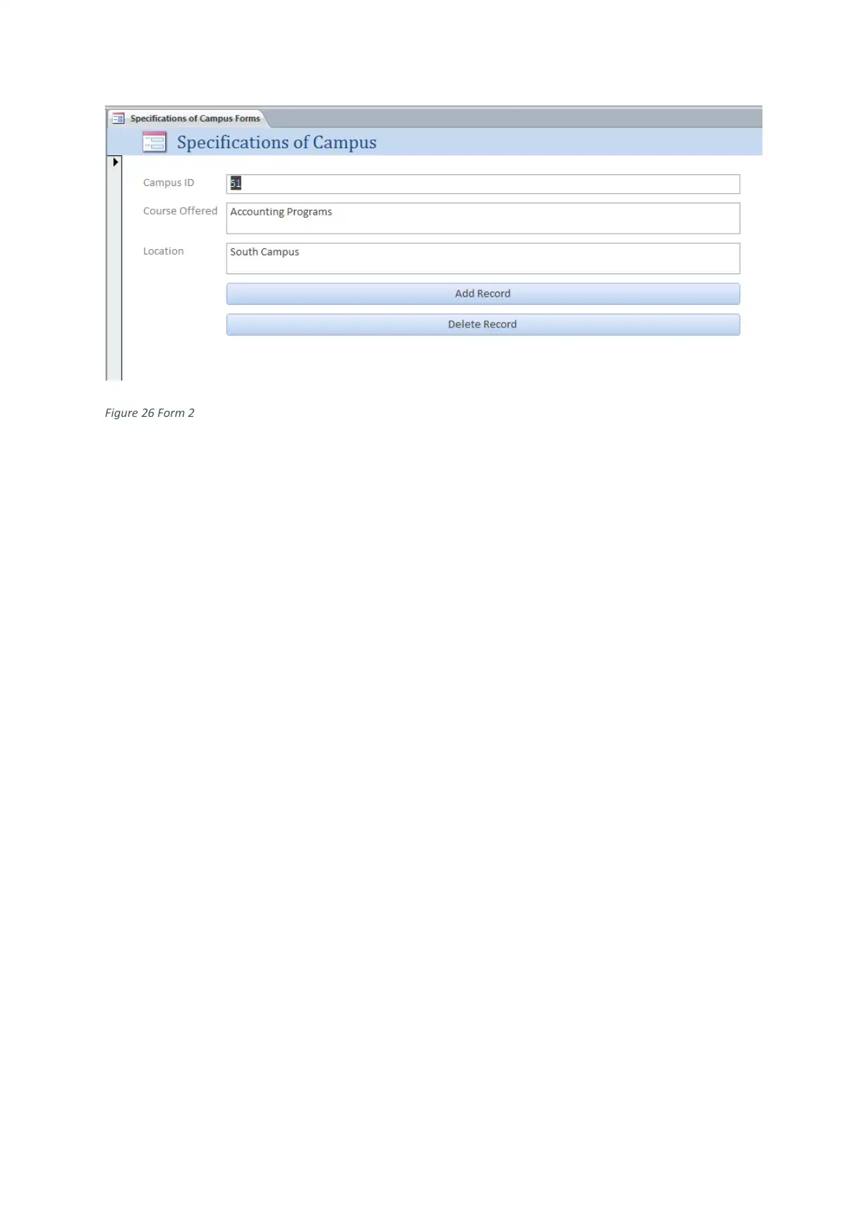
Figure 26 Form 2
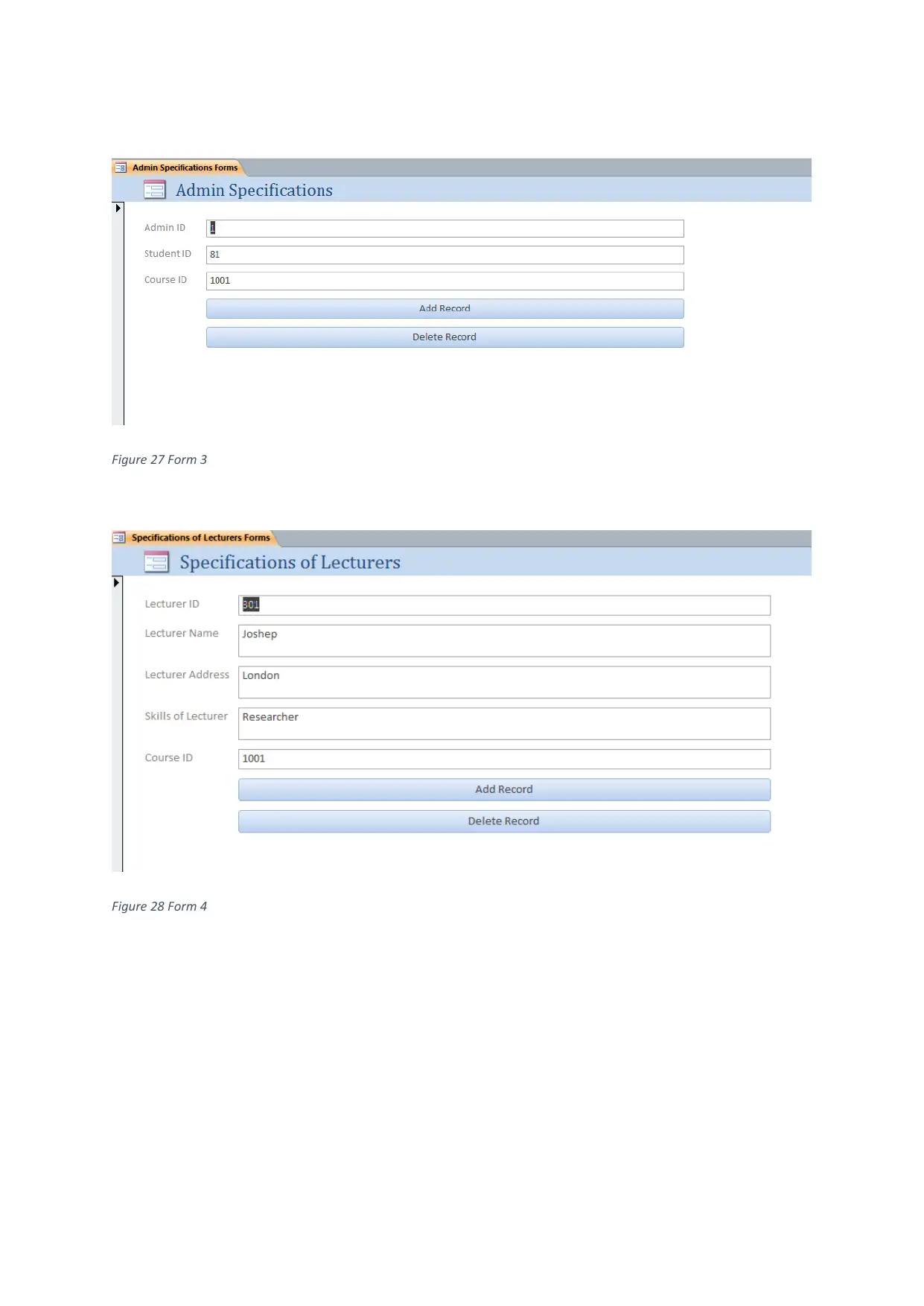
Figure 27 Form 3
Figure 28 Form 4
Figure 28 Form 4
Secure Best Marks with AI Grader
Need help grading? Try our AI Grader for instant feedback on your assignments.
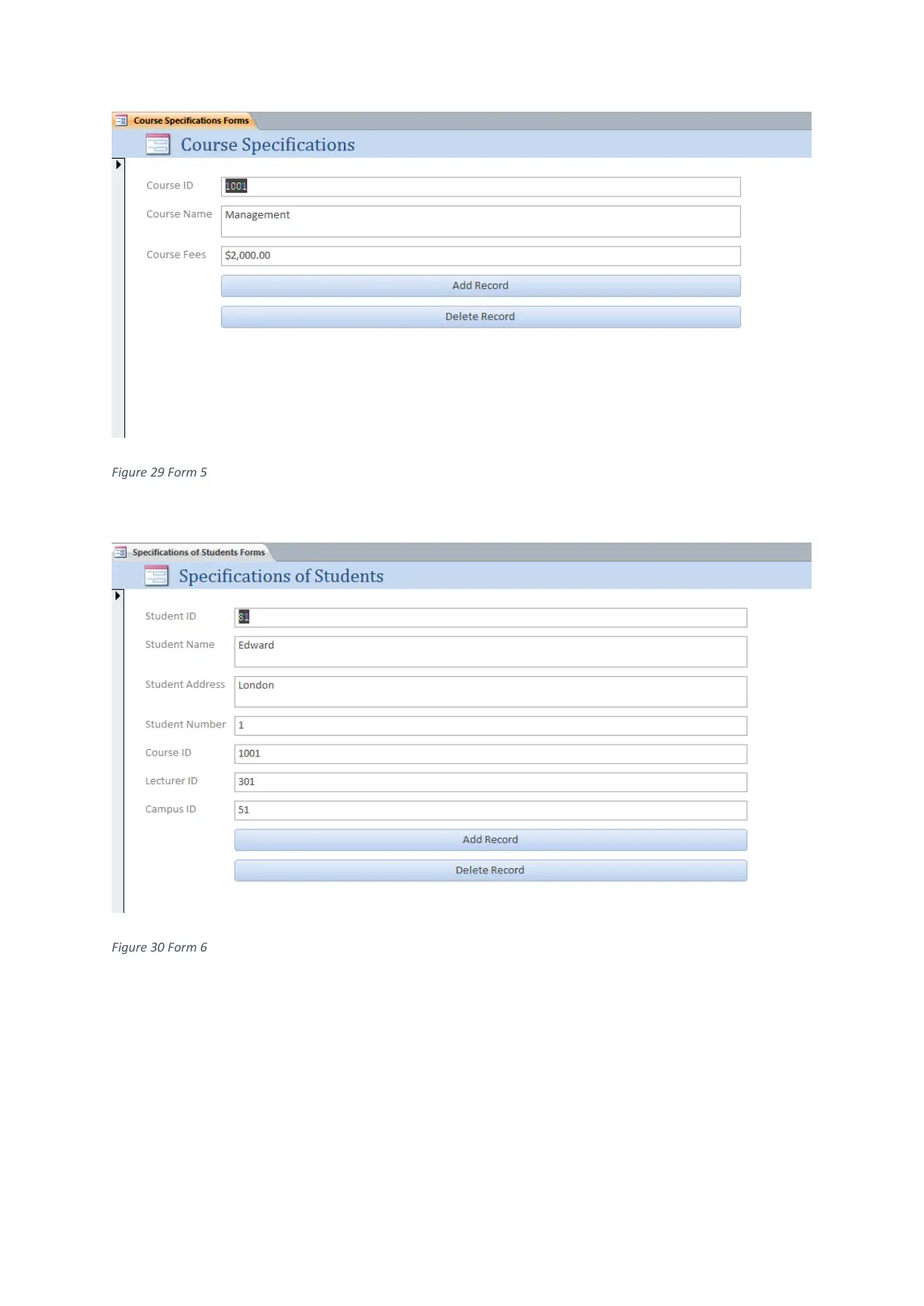
Figure 29 Form 5
Figure 30 Form 6
Figure 30 Form 6
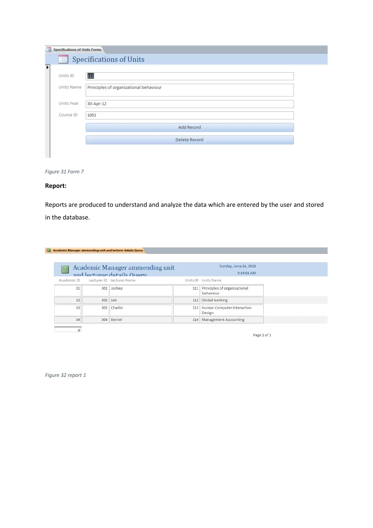
Figure 31 Form 7
Report:
Reports are produced to understand and analyze the data which are entered by the user and stored
in the database.
Figure 32 report 1
Report:
Reports are produced to understand and analyze the data which are entered by the user and stored
in the database.
Figure 32 report 1
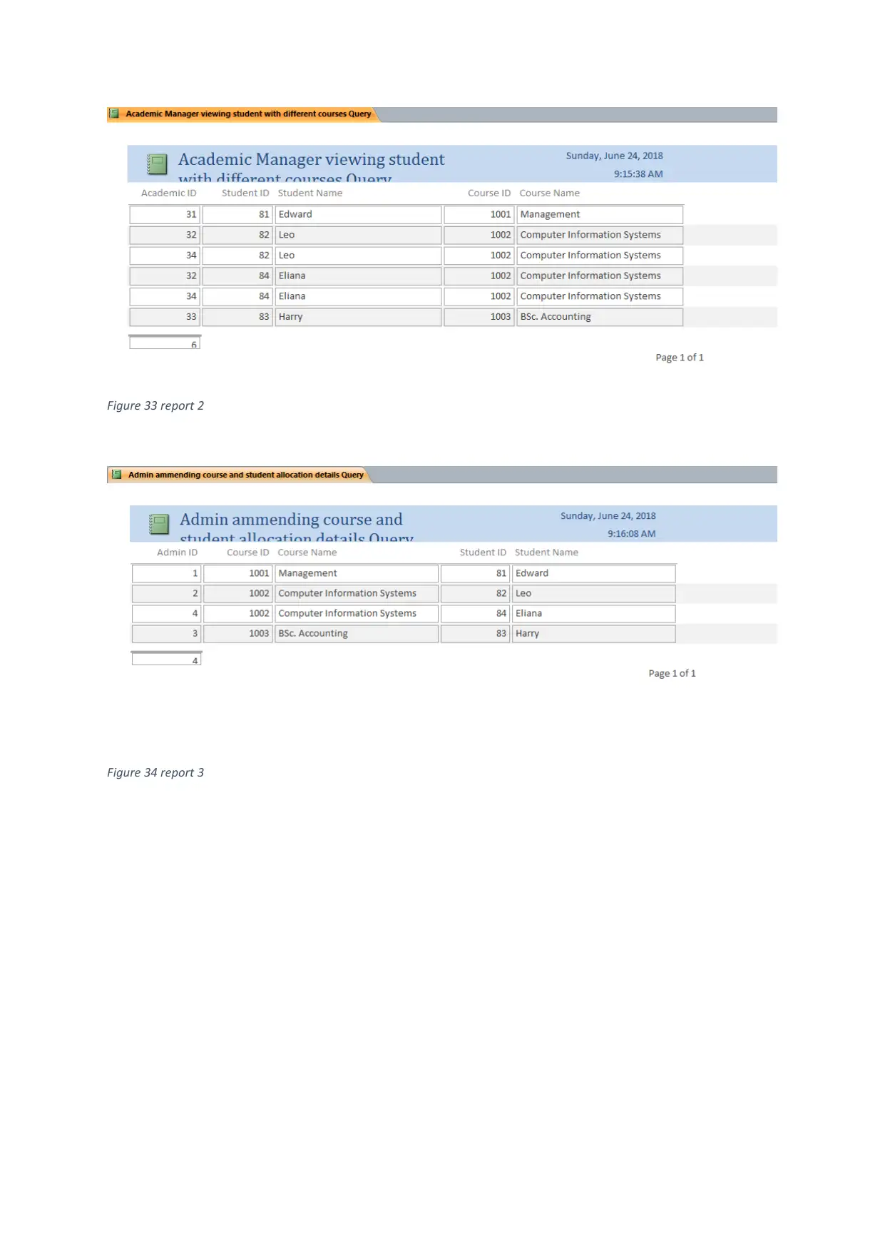
Figure 33 report 2
Figure 34 report 3
Figure 34 report 3
Paraphrase This Document
Need a fresh take? Get an instant paraphrase of this document with our AI Paraphraser
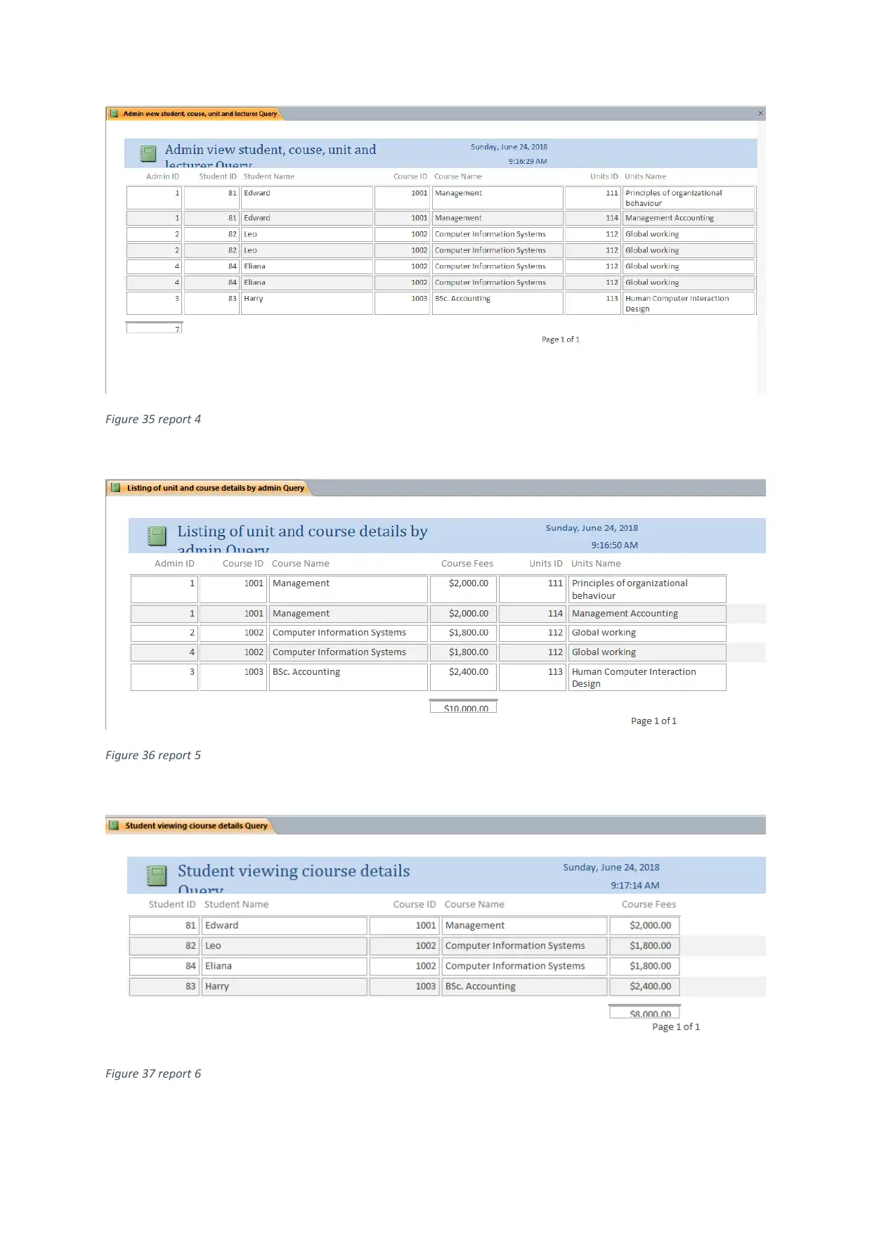
Figure 35 report 4
Figure 36 report 5
Figure 37 report 6
Figure 36 report 5
Figure 37 report 6
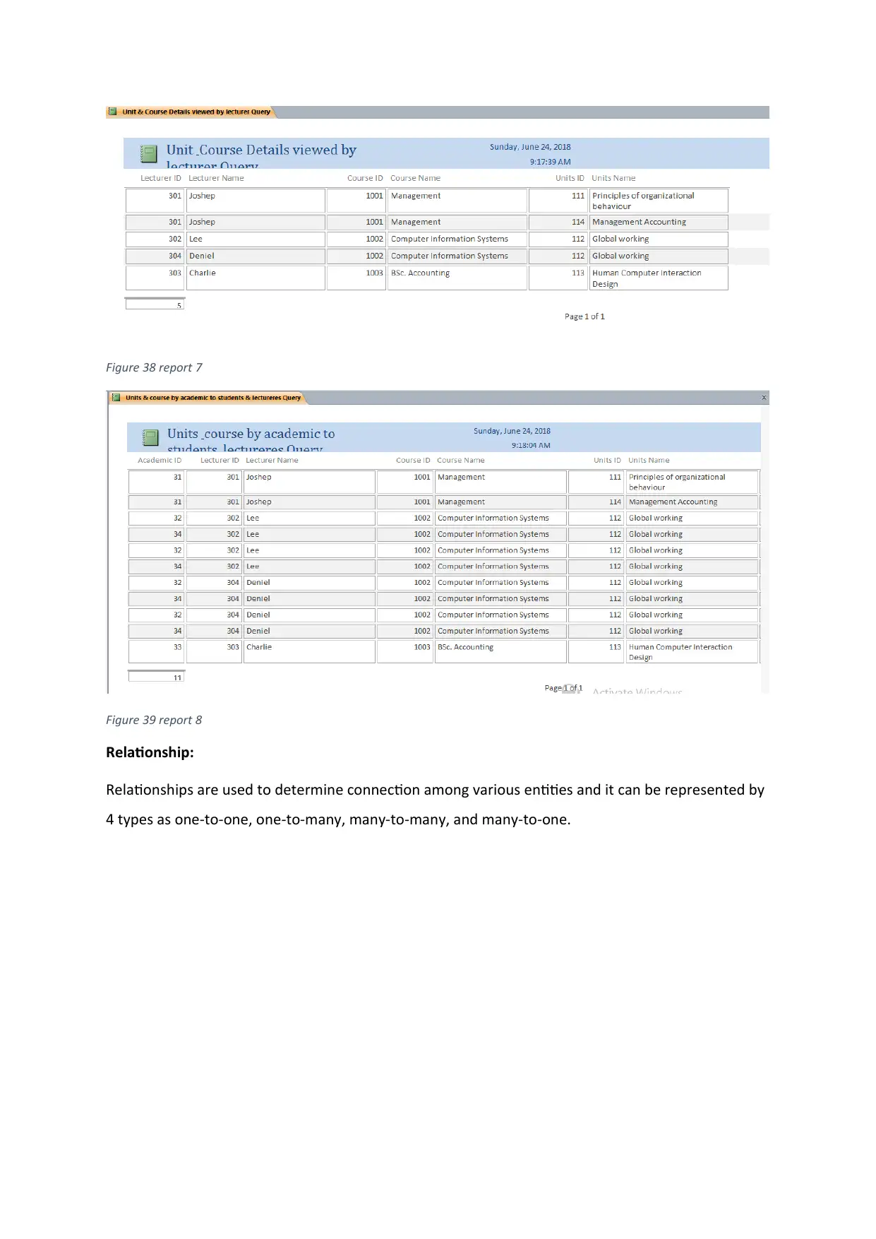
Figure 38 report 7
Figure 39 report 8
Relationship:
Relationships are used to determine connection among various entities and it can be represented by
4 types as one-to-one, one-to-many, many-to-many, and many-to-one.
Figure 39 report 8
Relationship:
Relationships are used to determine connection among various entities and it can be represented by
4 types as one-to-one, one-to-many, many-to-many, and many-to-one.
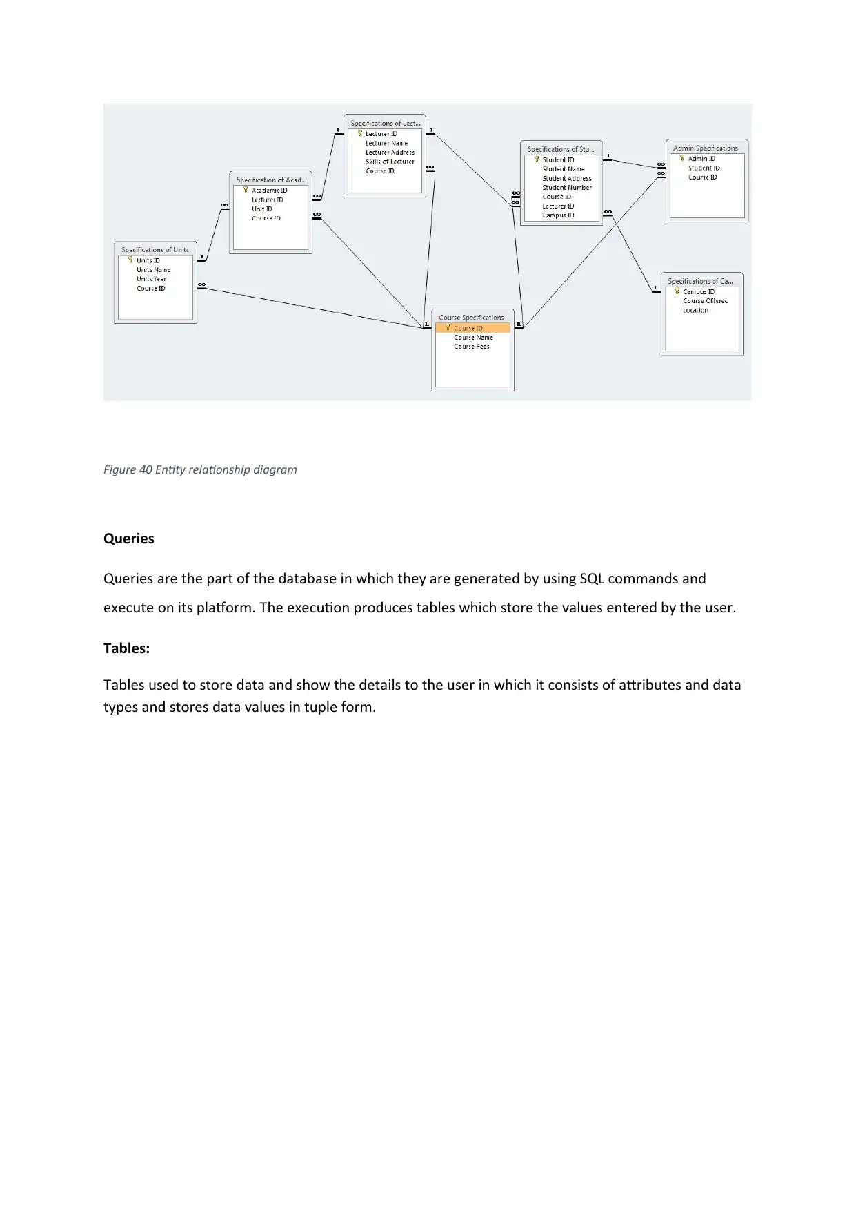
Figure 40 Entity relationship diagram
Queries
Queries are the part of the database in which they are generated by using SQL commands and
execute on its platform. The execution produces tables which store the values entered by the user.
Tables:
Tables used to store data and show the details to the user in which it consists of attributes and data
types and stores data values in tuple form.
Secure Best Marks with AI Grader
Need help grading? Try our AI Grader for instant feedback on your assignments.
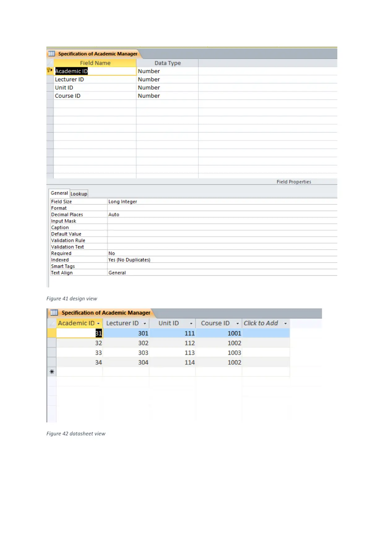
Figure 41 design view
Figure 42 datasheet view
Figure 42 datasheet view
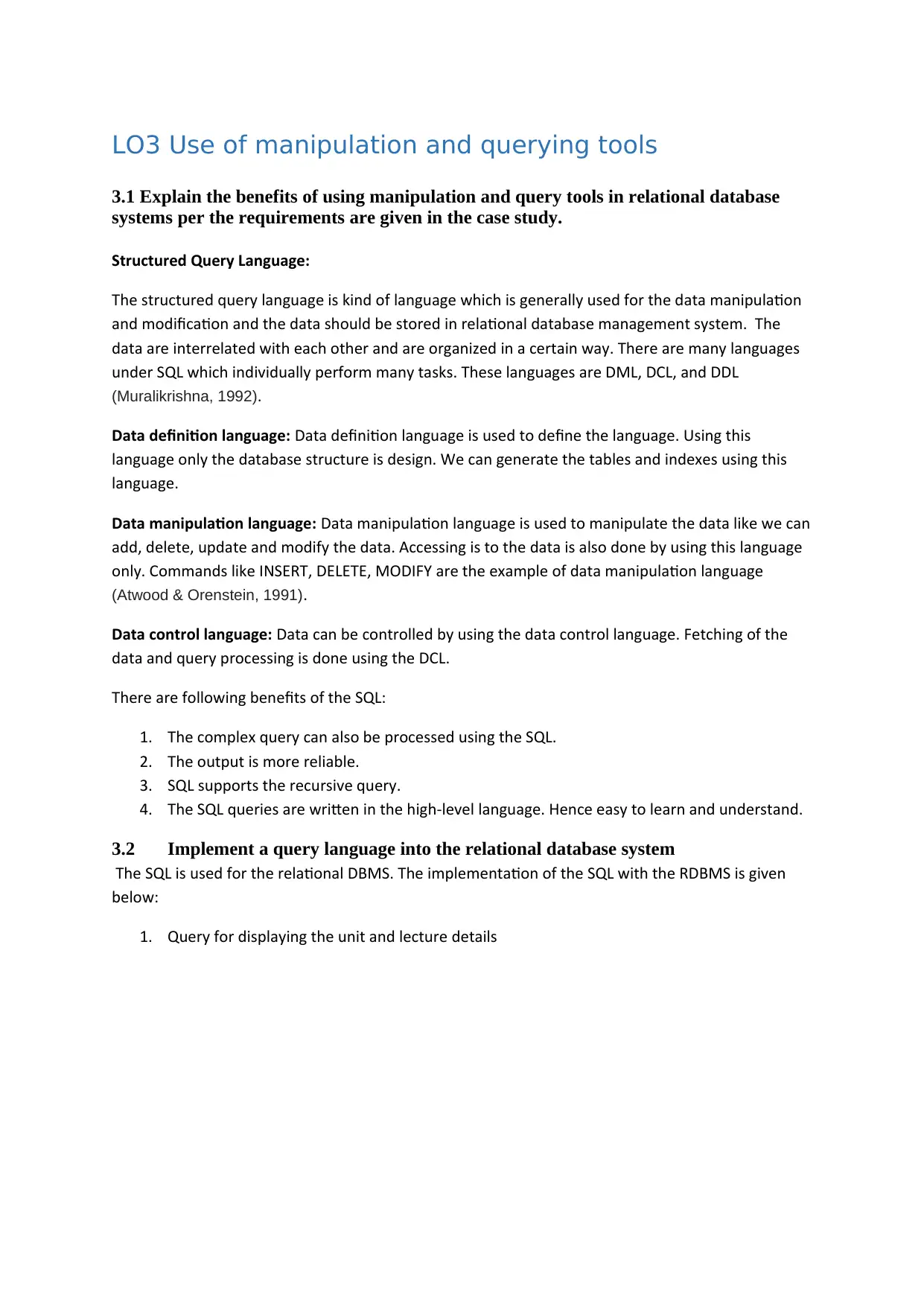
LO3 Use of manipulation and querying tools
3.1 Explain the benefits of using manipulation and query tools in relational database
systems per the requirements are given in the case study.
Structured Query Language:
The structured query language is kind of language which is generally used for the data manipulation
and modification and the data should be stored in relational database management system. The
data are interrelated with each other and are organized in a certain way. There are many languages
under SQL which individually perform many tasks. These languages are DML, DCL, and DDL
(Muralikrishna, 1992).
Data definition language: Data definition language is used to define the language. Using this
language only the database structure is design. We can generate the tables and indexes using this
language.
Data manipulation language: Data manipulation language is used to manipulate the data like we can
add, delete, update and modify the data. Accessing is to the data is also done by using this language
only. Commands like INSERT, DELETE, MODIFY are the example of data manipulation language
(Atwood & Orenstein, 1991).
Data control language: Data can be controlled by using the data control language. Fetching of the
data and query processing is done using the DCL.
There are following benefits of the SQL:
1. The complex query can also be processed using the SQL.
2. The output is more reliable.
3. SQL supports the recursive query.
4. The SQL queries are written in the high-level language. Hence easy to learn and understand.
3.2 Implement a query language into the relational database system
The SQL is used for the relational DBMS. The implementation of the SQL with the RDBMS is given
below:
1. Query for displaying the unit and lecture details
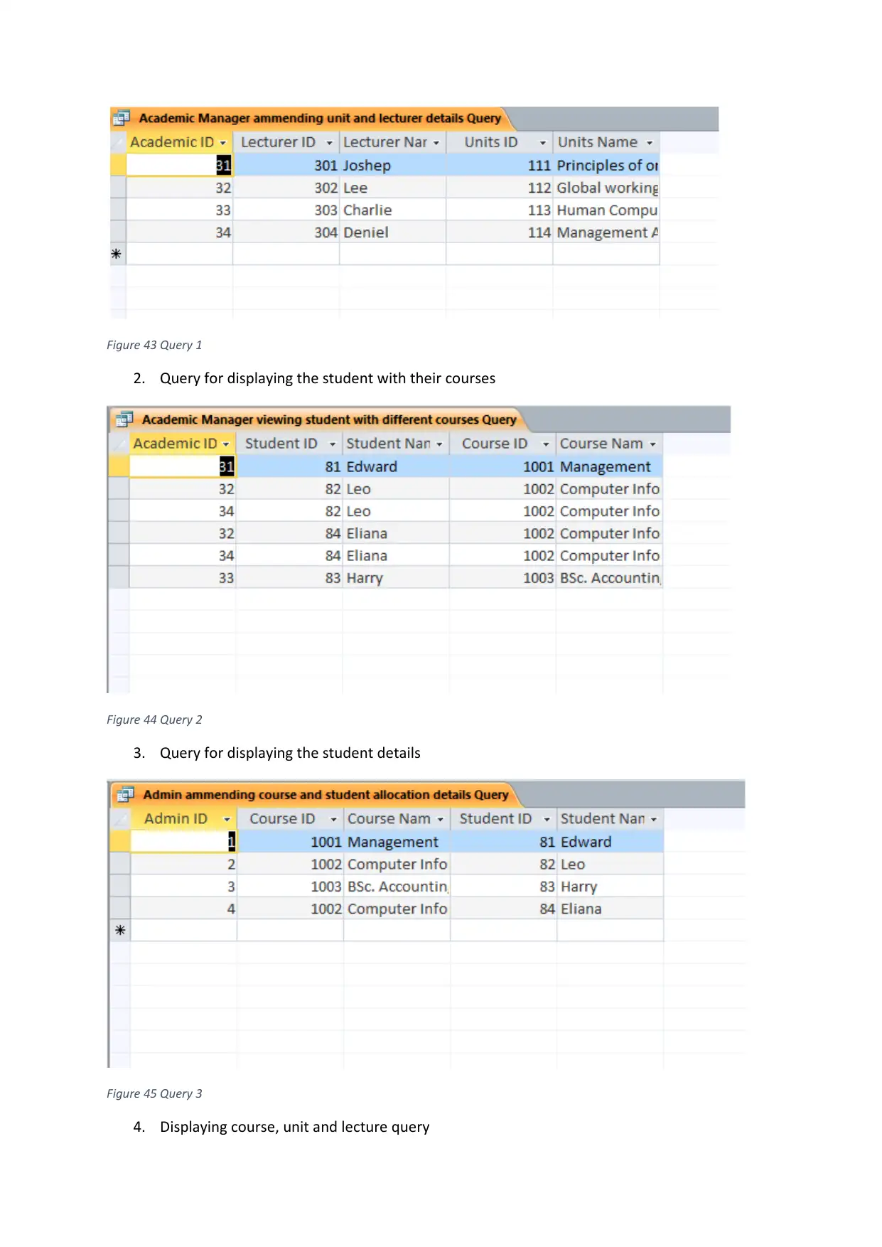
Figure 43 Query 1
2. Query for displaying the student with their courses
Figure 44 Query 2
3. Query for displaying the student details
Figure 45 Query 3
4. Displaying course, unit and lecture query
2. Query for displaying the student with their courses
Figure 44 Query 2
3. Query for displaying the student details
Figure 45 Query 3
4. Displaying course, unit and lecture query
Paraphrase This Document
Need a fresh take? Get an instant paraphrase of this document with our AI Paraphraser
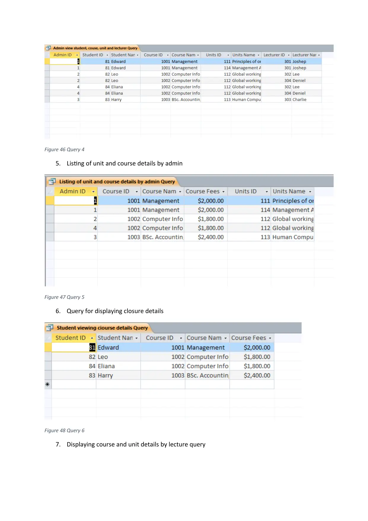
Figure 46 Query 4
5. Listing of unit and course details by admin
Figure 47 Query 5
6. Query for displaying closure details
Figure 48 Query 6
7. Displaying course and unit details by lecture query
5. Listing of unit and course details by admin
Figure 47 Query 5
6. Query for displaying closure details
Figure 48 Query 6
7. Displaying course and unit details by lecture query
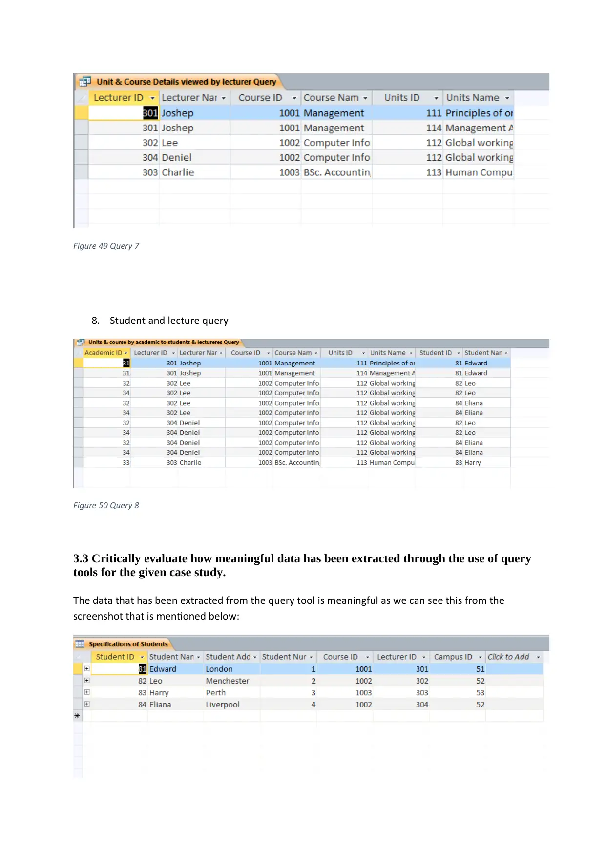
Figure 49 Query 7
8. Student and lecture query
Figure 50 Query 8
3.3 Critically evaluate how meaningful data has been extracted through the use of query
tools for the given case study.
The data that has been extracted from the query tool is meaningful as we can see this from the
screenshot that is mentioned below:
8. Student and lecture query
Figure 50 Query 8
3.3 Critically evaluate how meaningful data has been extracted through the use of query
tools for the given case study.
The data that has been extracted from the query tool is meaningful as we can see this from the
screenshot that is mentioned below:
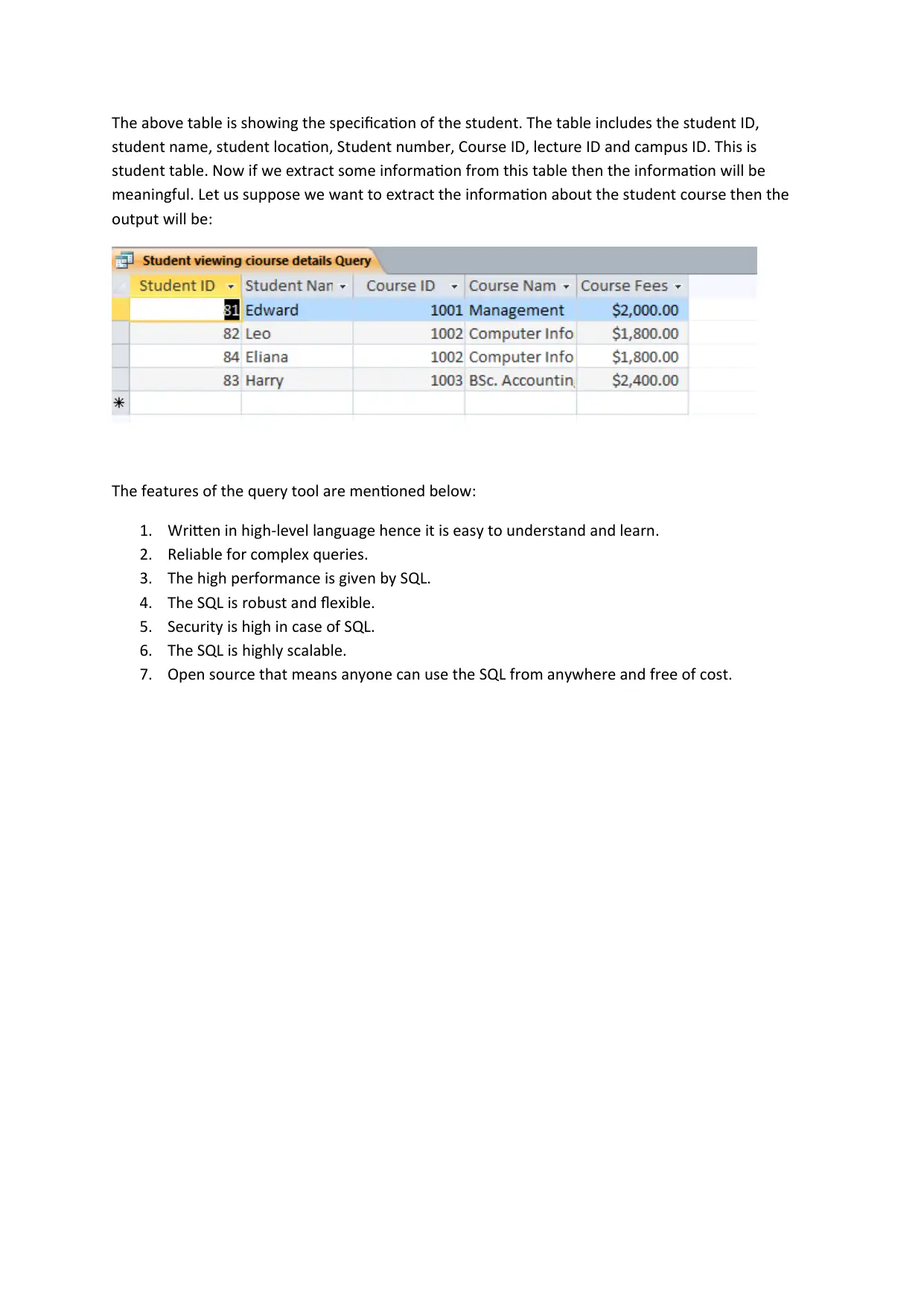
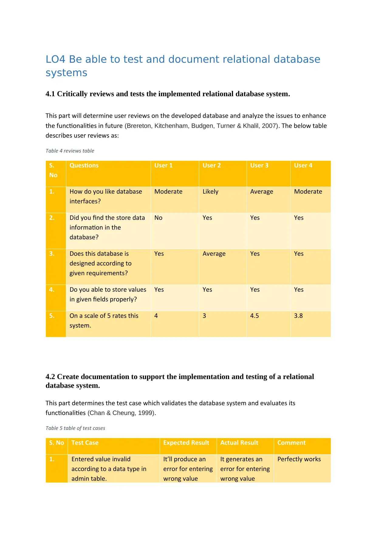
The above table is showing the specification of the student. The table includes the student ID,
student name, student location, Student number, Course ID, lecture ID and campus ID. This is
student table. Now if we extract some information from this table then the information will be
meaningful. Let us suppose we want to extract the information about the student course then the
output will be:
The features of the query tool are mentioned below:
1. Written in high-level language hence it is easy to understand and learn.
2. Reliable for complex queries.
3. The high performance is given by SQL.
4. The SQL is robust and flexible.
5. Security is high in case of SQL.
6. The SQL is highly scalable.
7. Open source that means anyone can use the SQL from anywhere and free of cost.
Secure Best Marks with AI Grader
Need help grading? Try our AI Grader for instant feedback on your assignments.
LO4 Be able to test and document relational database
systems
4.1 Critically reviews and tests the implemented relational database system.
This part will determine user reviews on the developed database and analyze the issues to enhance
the functionalities in future (Brereton, Kitchenham, Budgen, Turner & Khalil, 2007). The below table
describes user reviews as:
Table 4 reviews table
S.
No
Questions User 1 User 2 User 3 User 4
1. How do you like database
interfaces?
Moderate Likely Average Moderate
2. Did you find the store data
information in the
database?
No Yes Yes Yes
3. Does this database is
designed according to
given requirements?
Yes Average Yes Yes
4. Do you able to store values
in given fields properly?
Yes Yes Yes Yes
5. On a scale of 5 rates this
system.
4 3 4.5 3.8
4.2 Create documentation to support the implementation and testing of a relational
database system.
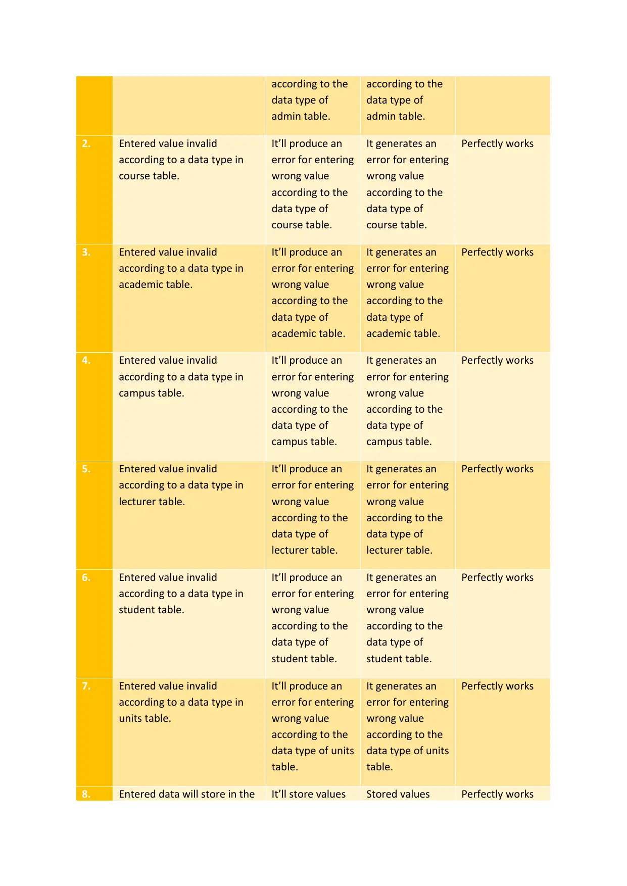
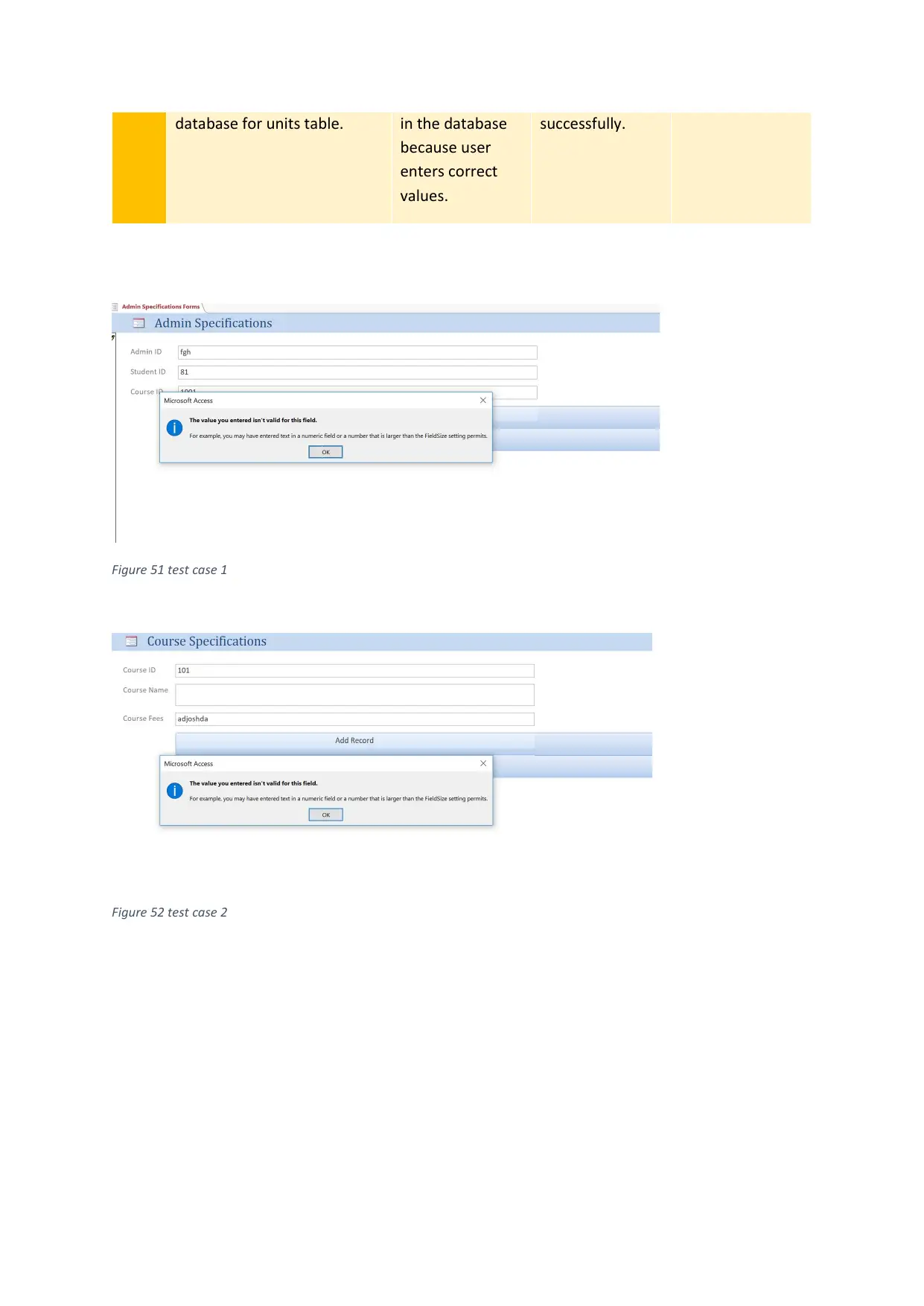
This part determines the test case which validates the database system and evaluates its
functionalities (Chan & Cheung, 1999).
Table 5 table of test cases
S. No Test Case Expected Result Actual Result Comment
1. Entered value invalid
according to a data type in
admin table.
It’ll produce an
error for entering
wrong value
It generates an
error for entering
wrong value
Perfectly works
according to the
data type of
admin table.
according to the
data type of
admin table.
2. Entered value invalid
according to a data type in
course table.
It’ll produce an
error for entering
wrong value
according to the
data type of
course table.
It generates an
error for entering
wrong value
according to the
data type of
course table.
Perfectly works
3. Entered value invalid
according to a data type in
academic table.
It’ll produce an
error for entering
wrong value
according to the
data type of
academic table.
It generates an
error for entering
wrong value
according to the
data type of
academic table.
Perfectly works
4. Entered value invalid
according to a data type in
campus table.
It’ll produce an
error for entering
wrong value
according to the
data type of
campus table.
It generates an
error for entering
wrong value
according to the
data type of
campus table.
Perfectly works
5. Entered value invalid
according to a data type in
lecturer table.
It’ll produce an
error for entering
wrong value
according to the
data type of
lecturer table.
It generates an
error for entering
wrong value
according to the
data type of
lecturer table.
Perfectly works
6. Entered value invalid
according to a data type in
student table.
It’ll produce an
error for entering
wrong value
according to the
data type of
student table.
It generates an
error for entering
wrong value
according to the
data type of
student table.
Perfectly works
7. Entered value invalid
according to a data type in
units table.
It’ll produce an
error for entering
wrong value
according to the
data type of units
table.
It generates an
error for entering
wrong value
according to the
data type of units
table.
Perfectly works
8. Entered data will store in the It’ll store values Stored values Perfectly works
data type of
admin table.
according to the
data type of
admin table.
2. Entered value invalid
according to a data type in
course table.
It’ll produce an
error for entering
wrong value
according to the
data type of
course table.
It generates an
error for entering
wrong value
according to the
data type of
course table.
Perfectly works
3. Entered value invalid
according to a data type in
academic table.
It’ll produce an
error for entering
wrong value
according to the
data type of
academic table.
It generates an
error for entering
wrong value
according to the
data type of
academic table.
Perfectly works
4. Entered value invalid
according to a data type in
campus table.
It’ll produce an
error for entering
wrong value
according to the
data type of
campus table.
It generates an
error for entering
wrong value
according to the
data type of
campus table.
Perfectly works
5. Entered value invalid
according to a data type in
lecturer table.
It’ll produce an
error for entering
wrong value
according to the
data type of
lecturer table.
It generates an
error for entering
wrong value
according to the
data type of
lecturer table.
Perfectly works
6. Entered value invalid
according to a data type in
student table.
It’ll produce an
error for entering
wrong value
according to the
data type of
student table.
It generates an
error for entering
wrong value
according to the
data type of
student table.
Perfectly works
7. Entered value invalid
according to a data type in
units table.
It’ll produce an
error for entering
wrong value
according to the
data type of units
table.
It generates an
error for entering
wrong value
according to the
data type of units
table.
Perfectly works
8. Entered data will store in the It’ll store values Stored values Perfectly works
database for units table. in the database
because user
enters correct
values.
successfully.
Figure 51 test case 1
Figure 52 test case 2
because user
enters correct
values.
successfully.
Figure 51 test case 1
Figure 52 test case 2
Paraphrase This Document
Need a fresh take? Get an instant paraphrase of this document with our AI Paraphraser
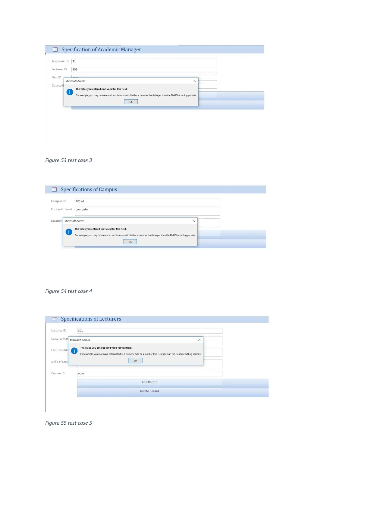
Figure 53 test case 3
Figure 54 test case 4
Figure 55 test case 5
Figure 54 test case 4
Figure 55 test case 5
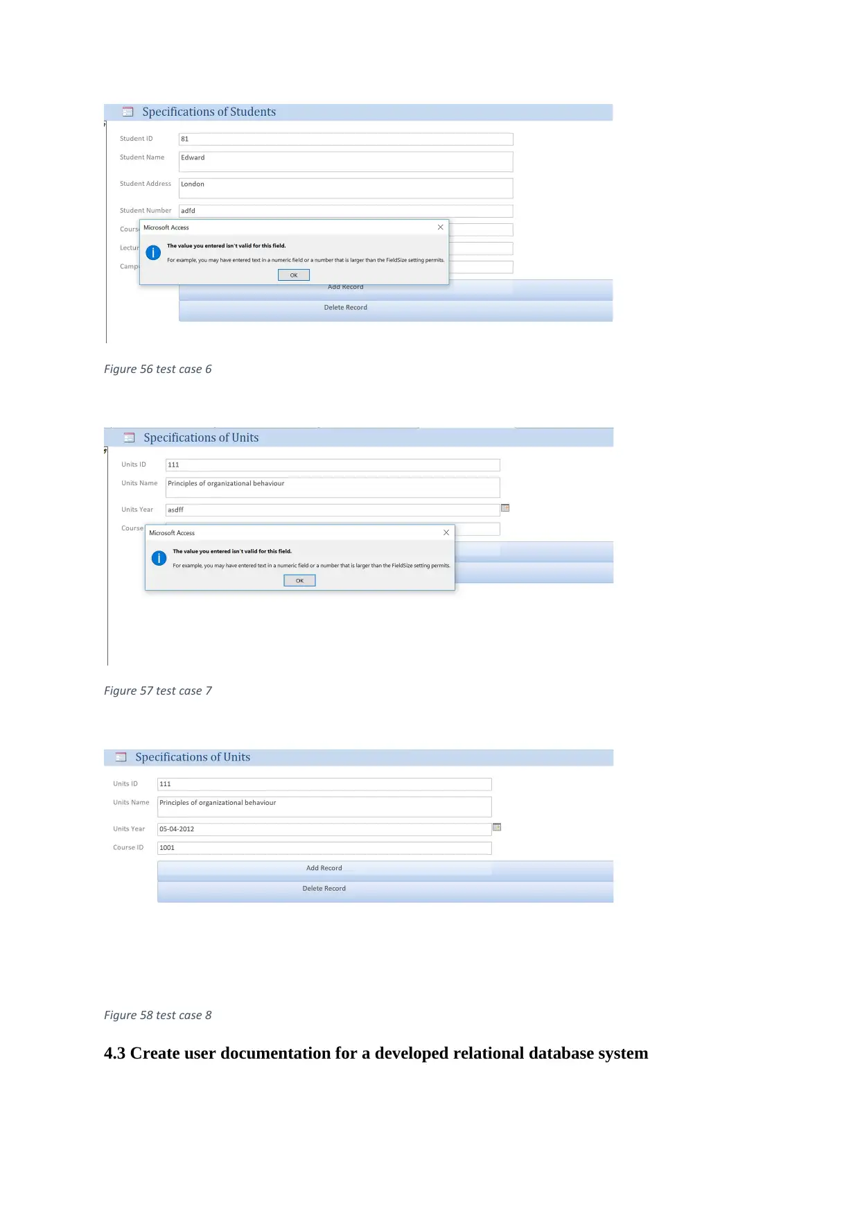
Figure 56 test case 6
Figure 57 test case 7
Figure 58 test case 8
4.3 Create user documentation for a developed relational database system
Figure 57 test case 7
Figure 58 test case 8
4.3 Create user documentation for a developed relational database system
User Documentation:
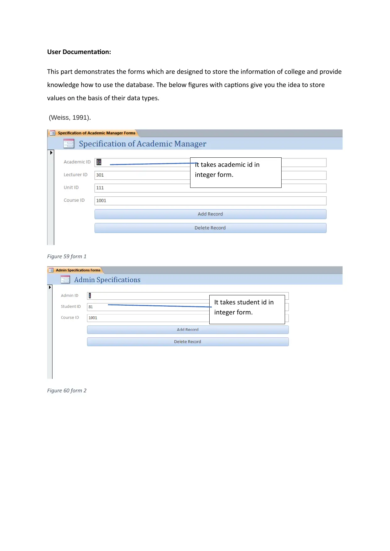
This part demonstrates the forms which are designed to store the information of college and provide
knowledge how to use the database. The below figures with captions give you the idea to store
values on the basis of their data types.
(Weiss, 1991).
Figure 59 form 1
Figure 60 form 2
It takes academic id in
integer form.
It takes student id in
integer form.
Secure Best Marks with AI Grader
Need help grading? Try our AI Grader for instant feedback on your assignments.
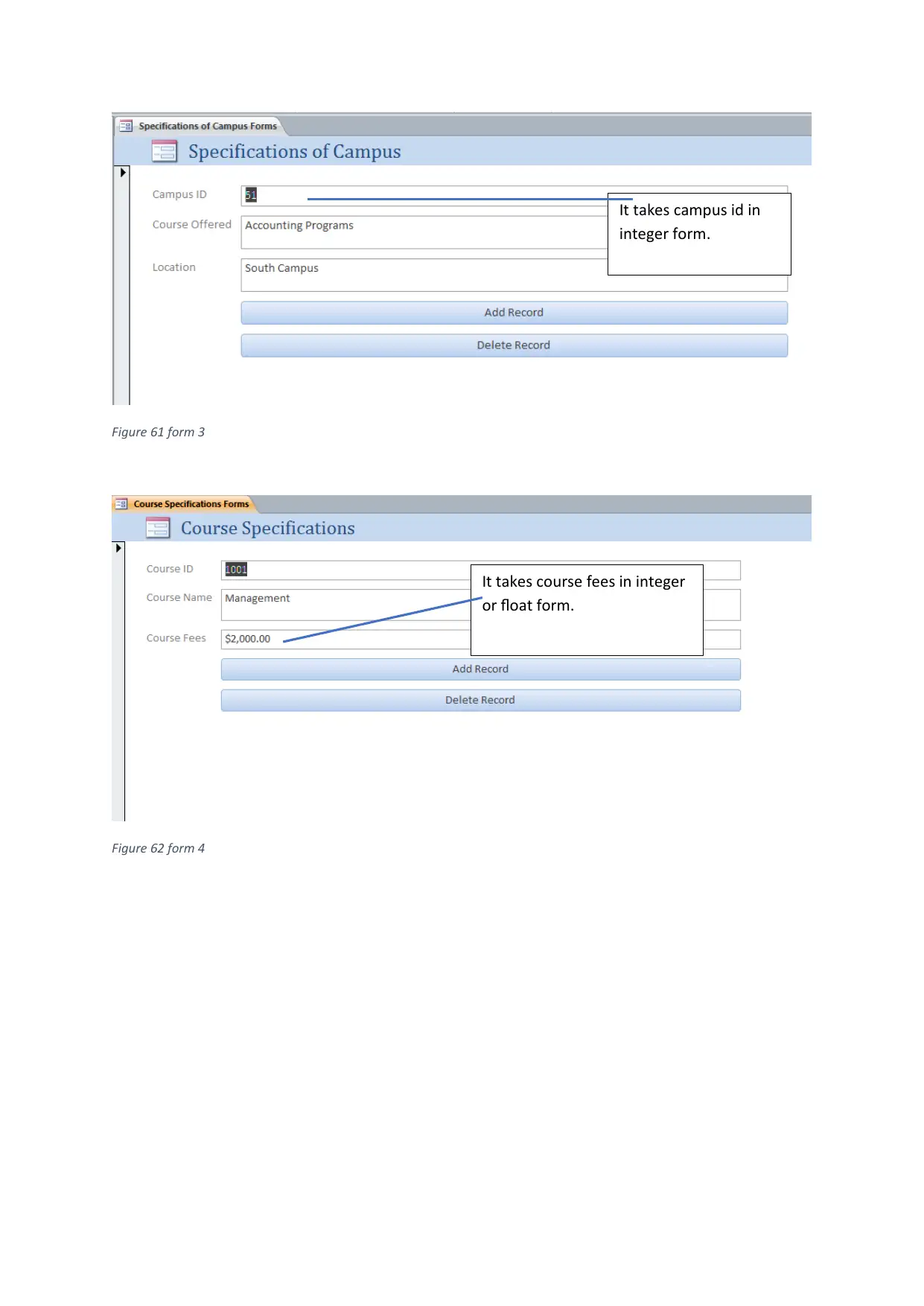
Figure 61 form 3
Figure 62 form 4
It takes campus id in
integer form.
It takes course fees in integer
or float form.
Figure 62 form 4
It takes campus id in
integer form.
It takes course fees in integer
or float form.
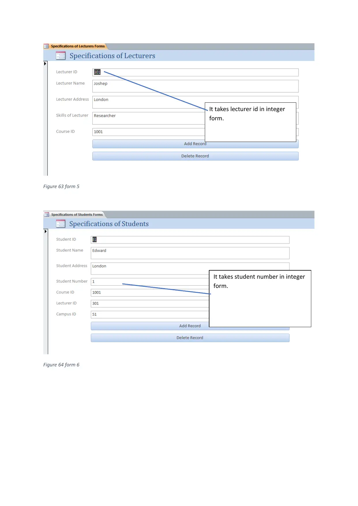
Figure 63 form 5
Figure 64 form 6
It takes lecturer id in integer
form.
It takes student number in integer
form.
Figure 64 form 6
It takes lecturer id in integer
form.
It takes student number in integer
form.
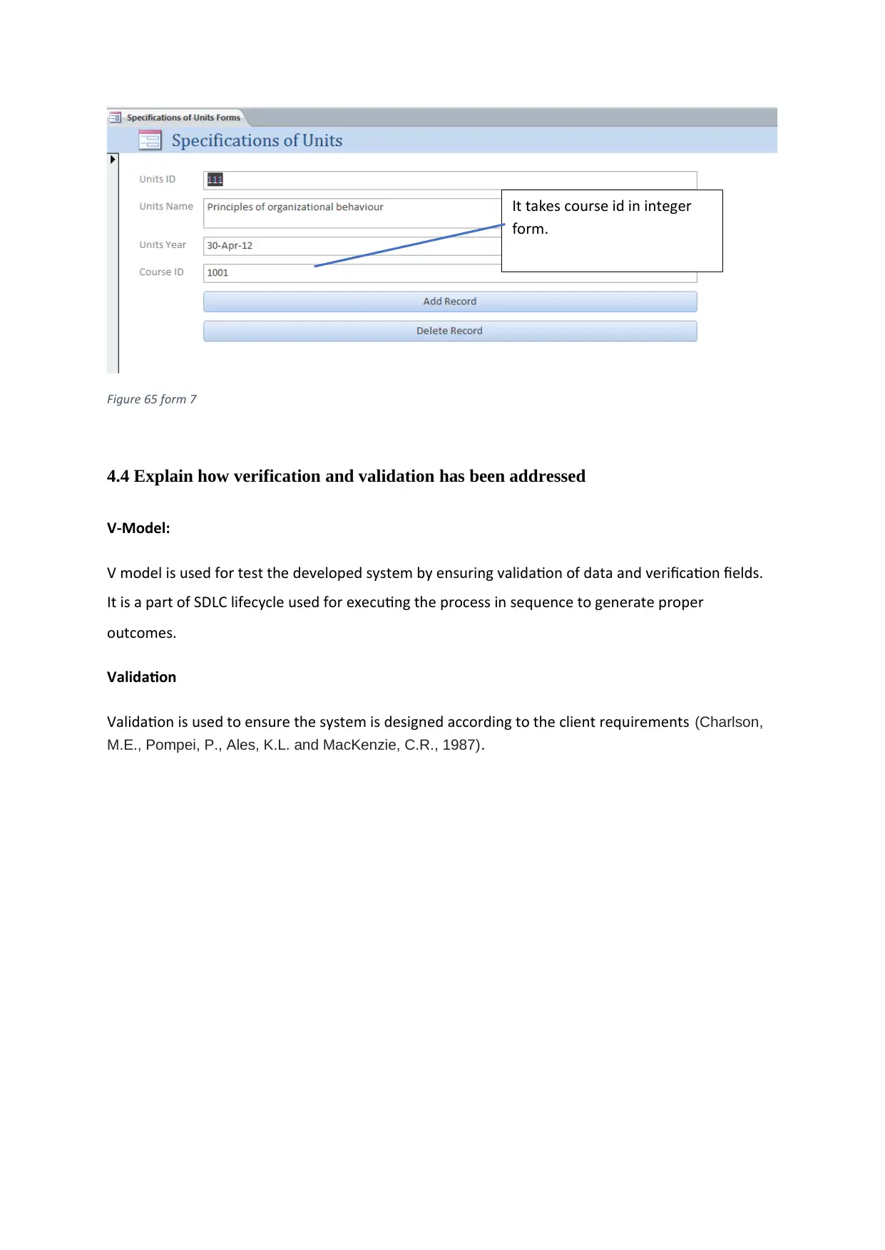
Figure 65 form 7
4.4 Explain how verification and validation has been addressed
V-Model:
V model is used for test the developed system by ensuring validation of data and verification fields.
It is a part of SDLC lifecycle used for executing the process in sequence to generate proper
outcomes.
Validation
Validation is used to ensure the system is designed according to the client requirements (Charlson,
M.E., Pompei, P., Ales, K.L. and MacKenzie, C.R., 1987).
It takes course id in integer
form.
Paraphrase This Document
Need a fresh take? Get an instant paraphrase of this document with our AI Paraphraser
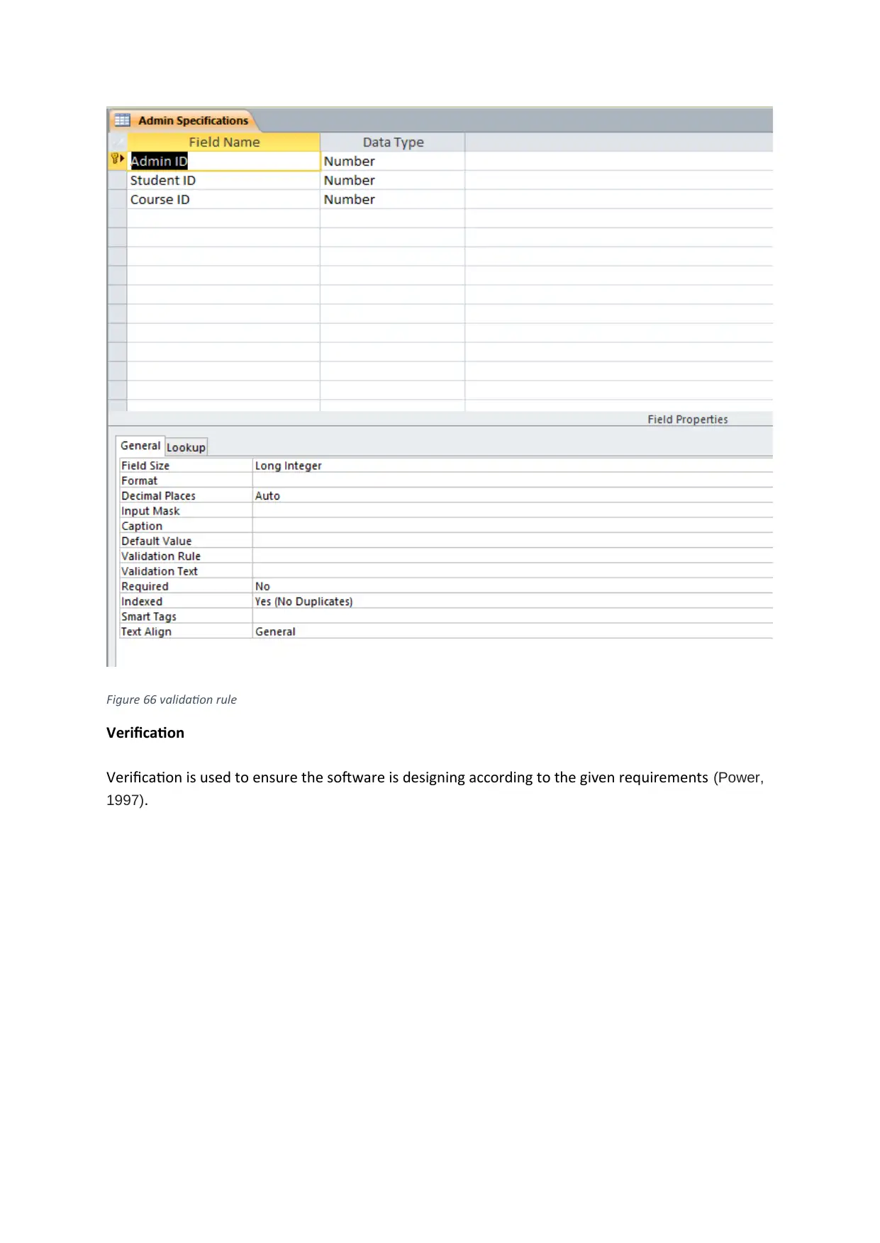
Figure 66 validation rule
Verification
Verification is used to ensure the software is designing according to the given requirements (Power,
1997).
Verification
Verification is used to ensure the software is designing according to the given requirements (Power,
1997).
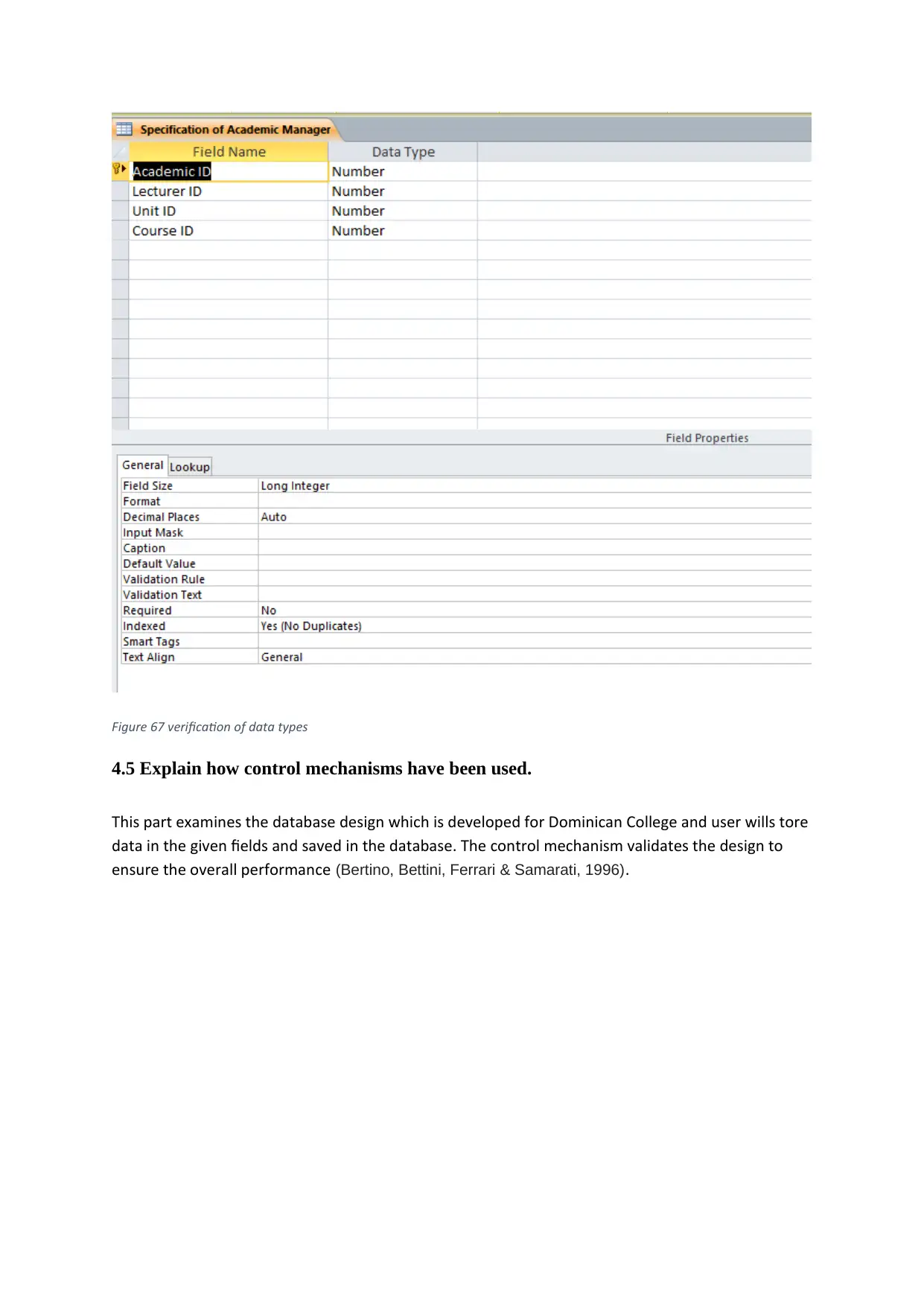
Figure 67 verification of data types
4.5 Explain how control mechanisms have been used.
This part examines the database design which is developed for Dominican College and user wills tore
data in the given fields and saved in the database. The control mechanism validates the design to
ensure the overall performance (Bertino, Bettini, Ferrari & Samarati, 1996).
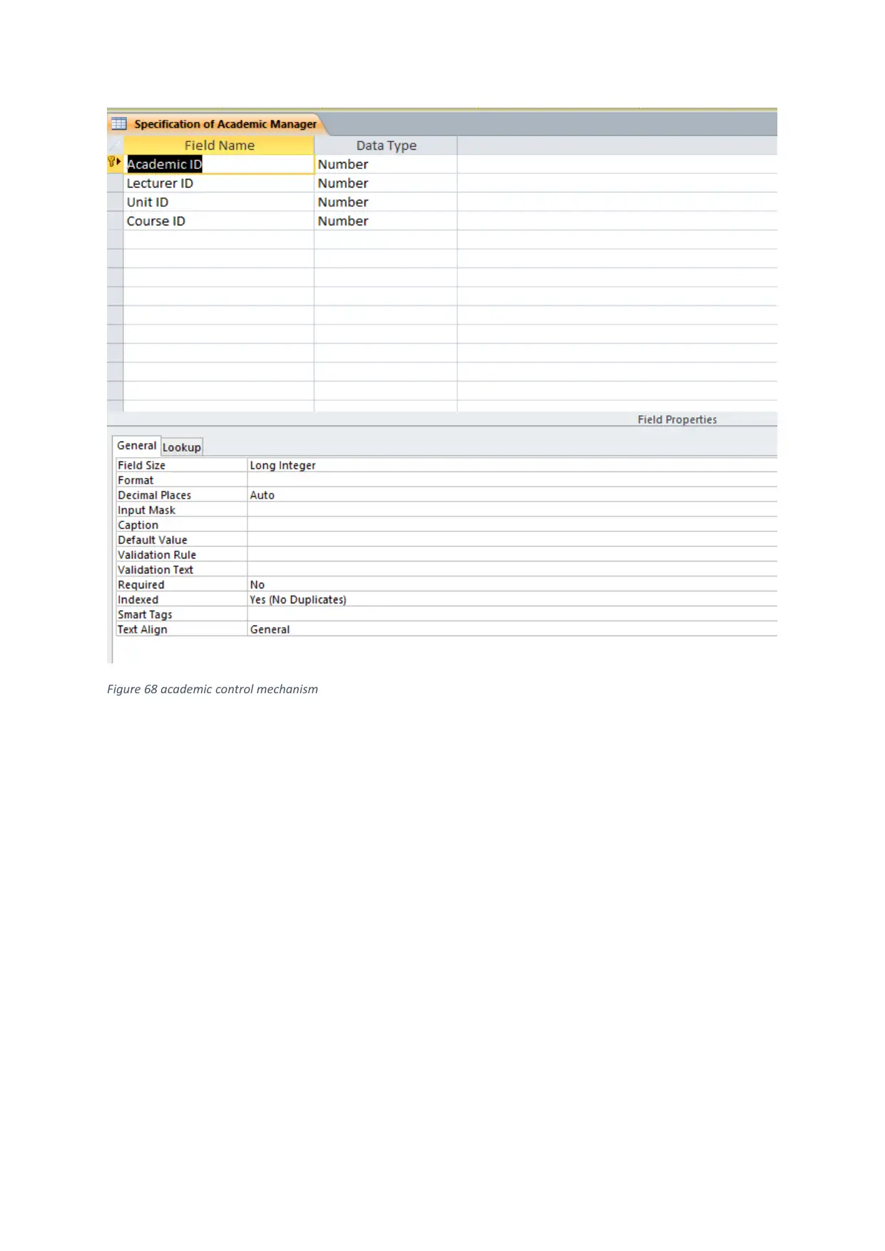
Figure 68 academic control mechanism
Secure Best Marks with AI Grader
Need help grading? Try our AI Grader for instant feedback on your assignments.
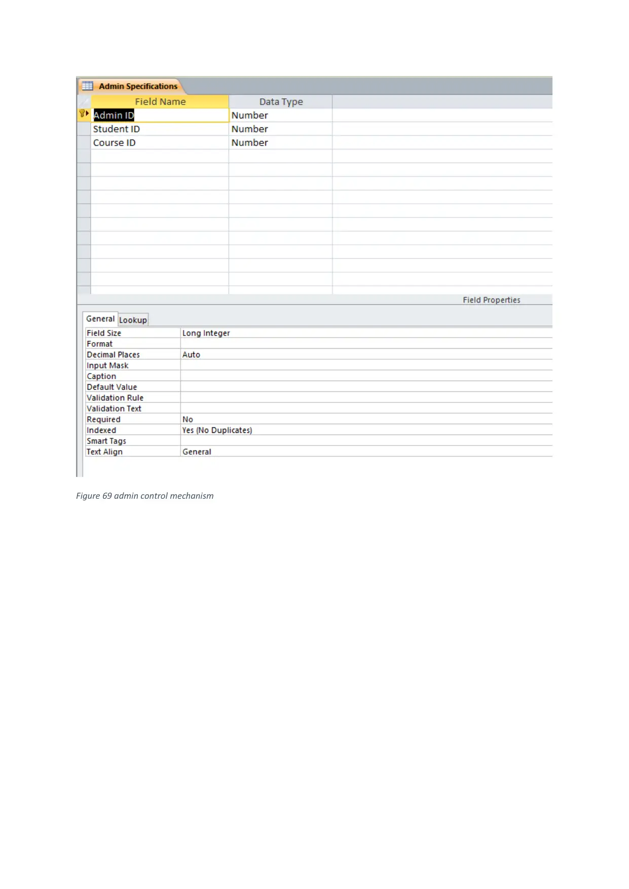
Figure 69 admin control mechanism
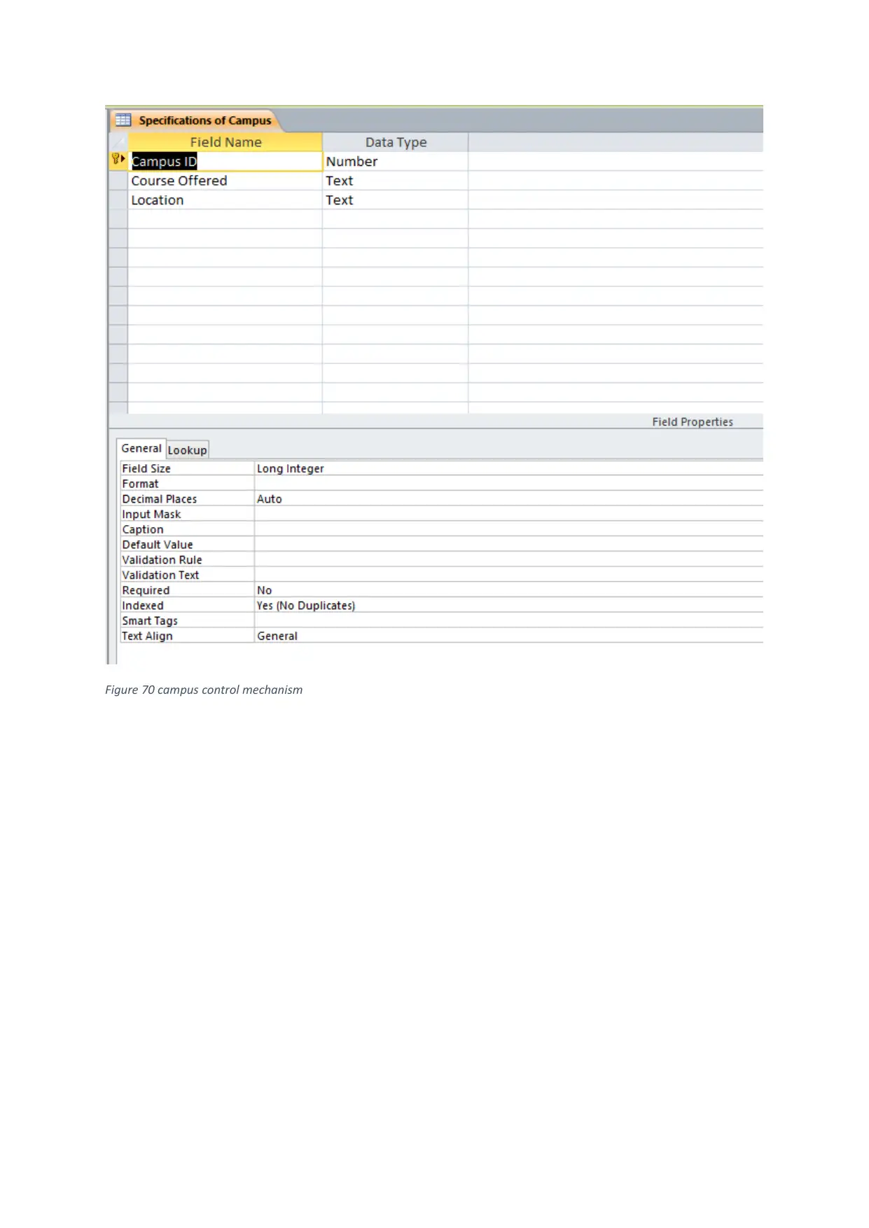
Figure 70 campus control mechanism
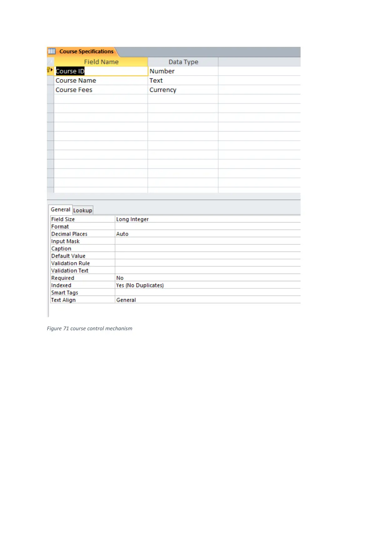
Figure 71 course control mechanism
Paraphrase This Document
Need a fresh take? Get an instant paraphrase of this document with our AI Paraphraser
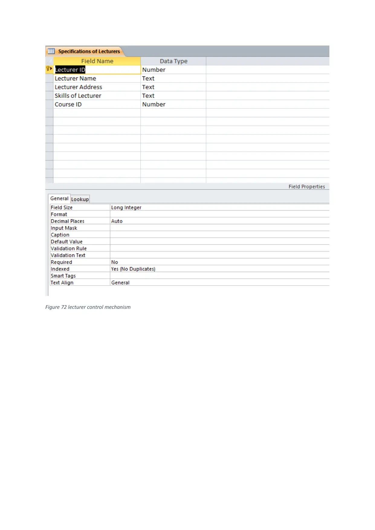
Figure 72 lecturer control mechanism
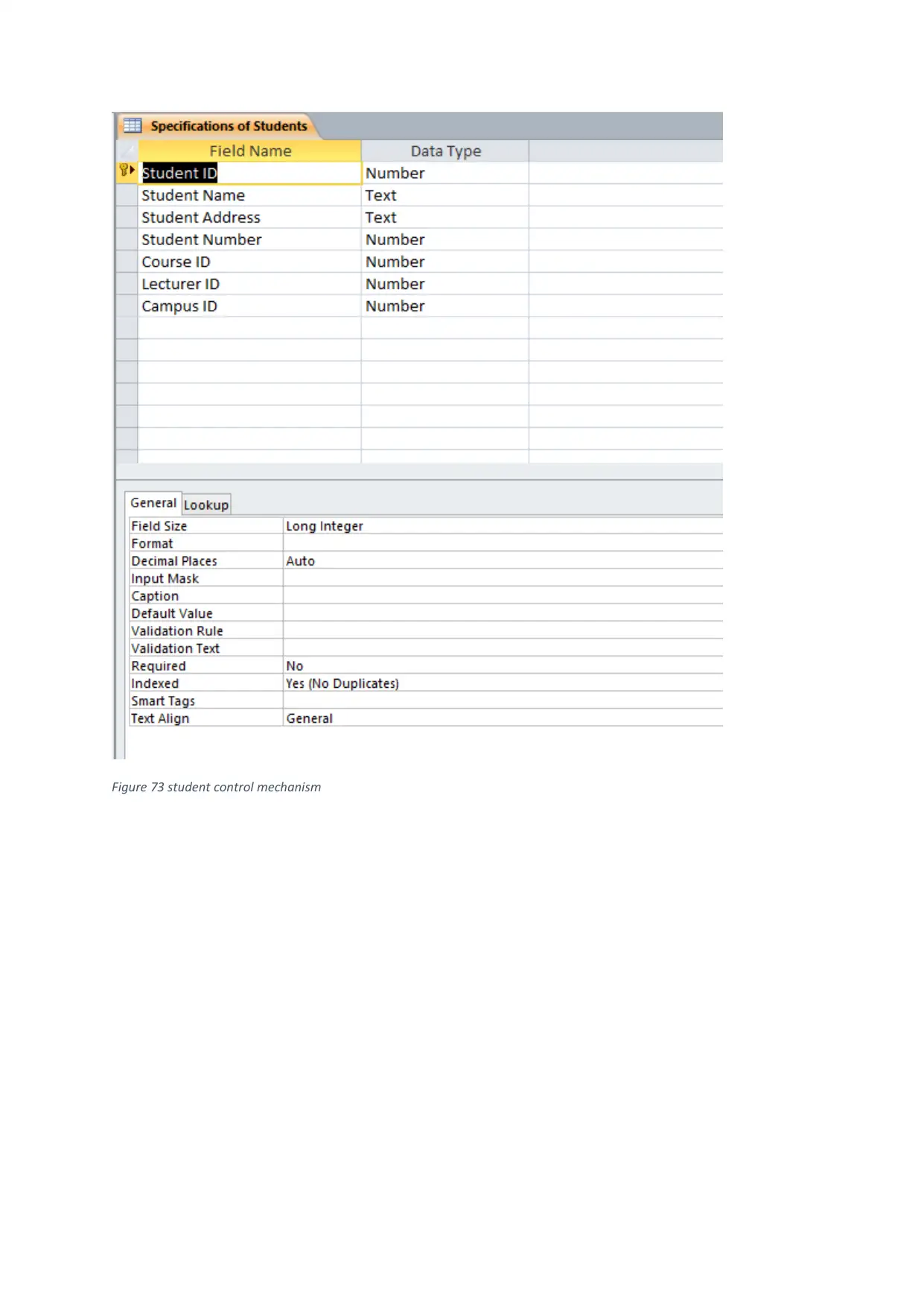
Figure 73 student control mechanism
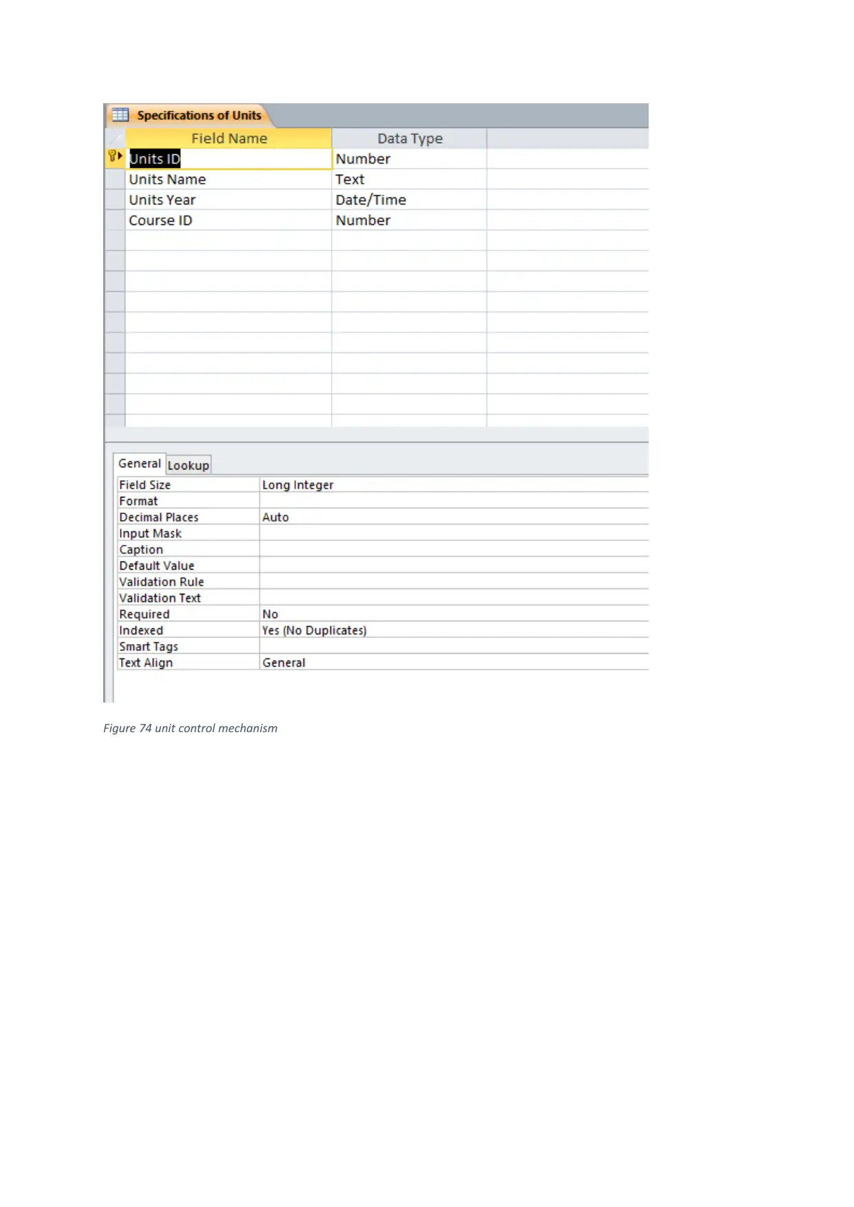
Figure 74 unit control mechanism
Secure Best Marks with AI Grader
Need help grading? Try our AI Grader for instant feedback on your assignments.

Conclusion
The report concludes that the database is designed for Dominican College by fulfilling their
requirements and create a database by including various entities and their relative fields to store
data information. The ER diagram help to understand the entities and their attributes along with the
relationship to diagnose system and create database accordingly. The database techniques give an
understanding of various components and later on user documentation provides knowledge of how
to store data in the given fields. The testing of the database is performed to endure the quality of
database and validates all the fields by describing in test case table. The control mechanism and V
model determines the validation rule and verification of requirements which are shown by
screenshots of some tables.
References
Weiss, E.H., 1991. How to write usable user documentation. Oryx Press, The.
Bertino, E., Bettini, C., Ferrari, E. and Samarati, P., 1996. A temporal access control
mechanism for database systems. IEEE Transactions on knowledge and data
engineering, 8(1), pp.67-80.
Charlson, M.E., Pompei, P., Ales, K.L. and MacKenzie, C.R., 1987. A new method of
classifying prognostic comorbidity in longitudinal studies: development and validation. Journal
of chronic diseases, 40(5), pp.373-383.
Power, M., 1997. The audit society: Rituals of verification. OUP Oxford.
Brereton, P., Kitchenham, B.A., Budgen, D., Turner, M. and Khalil, M., 2007. Lessons from
applying the systematic literature review process within the software engineering
domain. Journal of systems and software, 80(4), pp.571-583.
Chan, M.Y. and Cheung, S.C., 1999, March. Testing Database Applications with SQL
Semantics. In CODAS (Vol. 99, pp. 363-374).
Atwood, T. and Orenstein, J., 1991. Notes toward a standard Object-Oriented DDL and
DML. Computer standards & interfaces, 13(1-3), pp.117-121.
Muralikrishna, M., 1992, August. Improved unnesting algorithms for join aggregate SQL
queries. In VLDB (Vol. 92, pp. 91-102).
Chen, P.P.S., 1976. The entity-relationship model—toward a unified view of data. ACM
Transactions on Database Systems (TODS), 1(1), pp.9-36.
Elmasri, R. and Navathe, S., 2010. Fundamentals of database systems. Addison-Wesley
Publishing Company.
1 out of 60
Related Documents
Your All-in-One AI-Powered Toolkit for Academic Success.
+13062052269
info@desklib.com
Available 24*7 on WhatsApp / Email
![[object Object]](/_next/static/media/star-bottom.7253800d.svg)
Unlock your academic potential
© 2024 | Zucol Services PVT LTD | All rights reserved.


