Sunshine Motors: Database Design Report for Service Management System
VerifiedAdded on 2023/01/20
|27
|3556
|21
Report
AI Summary
This report details the database design for a software engineering project for "Sunshine Motors," a car dealership undergoing expansion. The report includes a specification document with an executive summary, system description, scope, feasibility analysis, functional and non-functional requirements, assumptions/constraints, use case diagrams and descriptions, context model, and leveled functional models. It also contains a design document with an executive summary, architectural design, hardware specifications, detailed class diagrams, interface designs (wireframes), business process models (BPMN 2.0), sequence diagrams, interaction diagrams, and state diagrams. The system aims to manage client information, vehicle details, service history, and mechanic records, streamlining operations and addressing challenges in the company's current manual data management processes. The report provides a thorough analysis of the system's requirements and design, offering a comprehensive guide to its development and implementation.
1Database in Software Engineer
DATABASE IN SOFTWARE ENGINEER
[Student name]
[University name]
[Professor Name]
[Date]
DATABASE IN SOFTWARE ENGINEER
[Student name]
[University name]
[Professor Name]
[Date]
Paraphrase This Document
Need a fresh take? Get an instant paraphrase of this document with our AI Paraphraser
2Database in Software Engineer
Table of Contents
List of figures...............................................................................................................................................3
List of tables................................................................................................................................................3
1. Specification Document.......................................................................................................................4
a. Executive Summary.........................................................................................................................4
b. System Description..........................................................................................................................4
c. Scope...............................................................................................................................................5
d. Feasibility Analysis.........................................................................................................................5
e. Requirements Specification.............................................................................................................6
i. Functional....................................................................................................................................6
ii. Non-Functional............................................................................................................................7
f. Assumptions/ Constraints................................................................................................................7
g. Use Cases (from functional requirements) (at least 4 per group)....................................................7
i. Use Case Diagrams..........................................................................................................................7
e. Use Case Descriptions......................................................................................................................9
h. Context Model...............................................................................................................................12
i. Leveled Set of Functional Models..................................................................................................12
2. Design Document..............................................................................................................................14
a. Executive Summary.......................................................................................................................14
b. Architectural Design......................................................................................................................14
c. Hardware Specifications................................................................................................................15
d. Detailed Class Diagram..................................................................................................................16
e. Interface Design (at least 4 per group)..........................................................................................17
i. Wireframe Diagrams..................................................................................................................17
f. Business Process Models (utilizing BPMN 2.0) (at least 4 per group)............................................19
e. Sequence Diagrams (at least 4 per group).....................................................................................20
e. Interaction Diagrams (at least 4 per group)...................................................................................22
e. State Diagrams (at least 4 per group)............................................................................................24
Reference..................................................................................................................................................28
3Database in Software Engineer
List of figures
Figure 1: First use case diagram..................................................................................................................8
Figure 2: Second use case diagram..............................................................................................................8
Figure 3:Third use case diagram..................................................................................................................9
Figure 4:Forth use case diagram..................................................................................................................9
Figure 5:Context Model.............................................................................................................................12
Figure 6: Level 0 DFD diagram...................................................................................................................12
Figure 7: Level 1 DFD diagram...................................................................................................................13
Figure 8: Architectural Design...................................................................................................................14
Figure 9:Detailed Class Diagram................................................................................................................16
Figure 10: Home page wireframe..............................................................................................................17
Figure 11: Staffs register form wireframe..................................................................................................17
Figure 12: User login form wireframe........................................................................................................18
Figure 13: Mechanic registration form wireframe.....................................................................................18
Figure 14: First business process...............................................................................................................19
Figure 15: Second business process..........................................................................................................19
Figure 16: Third business process..............................................................................................................19
Figure 17: Forth business process.............................................................................................................20
Figure 18: Sequence one...........................................................................................................................20
Figure 19: Sequence two...........................................................................................................................21
Figure 20: Sequence three.........................................................................................................................21
Figure 21: Sequence four...........................................................................................................................22
Figure 22: First Interaction diagram..........................................................................................................22
Figure 23:Second Interaction diagram.......................................................................................................23
Figure 24: Third Interaction diagram.........................................................................................................23
Figure 25: Fourth Interaction diagram.......................................................................................................24
Figure 26: First state chart diagrams.........................................................................................................24
Figure 27: Second state chart diagrams.....................................................................................................25
Figure 28: Third state chart diagrams........................................................................................................26
Figure 29: Fourth state chart diagrams.....................................................................................................27
List of tables
Table 1:First use case diagram descriptions................................................................................................9
Table 2: Second use case diagram descriptions.........................................................................................10
Table 3: Third use case diagram descriptions............................................................................................11
⊘ This is a preview!⊘
Do you want full access?
Subscribe today to unlock all pages.
Trusted by 1+ million students worldwide
4Database in Software Engineer
Table 4: Forth use case diagram descriptions............................................................................................11
Table 5: Hardware Specifications..............................................................................................................15
1. Specification Document
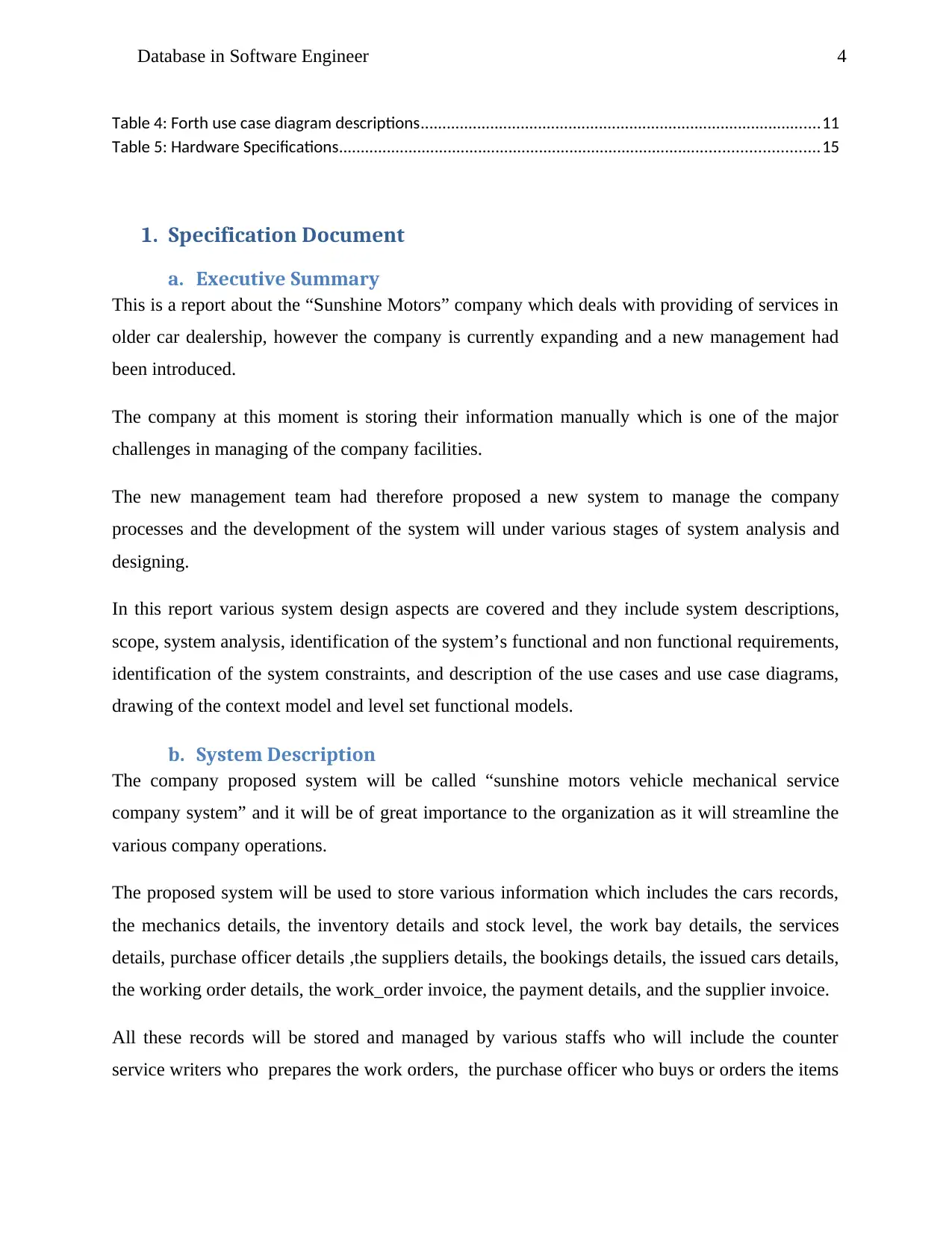
a. Executive Summary
This is a report about the “Sunshine Motors” company which deals with providing of services in
older car dealership, however the company is currently expanding and a new management had
been introduced.
The company at this moment is storing their information manually which is one of the major
challenges in managing of the company facilities.
The new management team had therefore proposed a new system to manage the company
processes and the development of the system will under various stages of system analysis and
designing.
In this report various system design aspects are covered and they include system descriptions,
scope, system analysis, identification of the system’s functional and non functional requirements,
identification of the system constraints, and description of the use cases and use case diagrams,
drawing of the context model and level set functional models.
b. System Description
The company proposed system will be called “sunshine motors vehicle mechanical service
company system” and it will be of great importance to the organization as it will streamline the
various company operations.
The proposed system will be used to store various information which includes the cars records,
the mechanics details, the inventory details and stock level, the work bay details, the services
details, purchase officer details ,the suppliers details, the bookings details, the issued cars details,
the working order details, the work_order invoice, the payment details, and the supplier invoice.
All these records will be stored and managed by various staffs who will include the counter
service writers who prepares the work orders, the purchase officer who buys or orders the items
Table 4: Forth use case diagram descriptions............................................................................................11
Table 5: Hardware Specifications..............................................................................................................15
1. Specification Document
a. Executive Summary
This is a report about the “Sunshine Motors” company which deals with providing of services in
older car dealership, however the company is currently expanding and a new management had
been introduced.
The company at this moment is storing their information manually which is one of the major
challenges in managing of the company facilities.
The new management team had therefore proposed a new system to manage the company
processes and the development of the system will under various stages of system analysis and
designing.
In this report various system design aspects are covered and they include system descriptions,
scope, system analysis, identification of the system’s functional and non functional requirements,
identification of the system constraints, and description of the use cases and use case diagrams,
drawing of the context model and level set functional models.
b. System Description
The company proposed system will be called “sunshine motors vehicle mechanical service
company system” and it will be of great importance to the organization as it will streamline the
various company operations.
The proposed system will be used to store various information which includes the cars records,
the mechanics details, the inventory details and stock level, the work bay details, the services
details, purchase officer details ,the suppliers details, the bookings details, the issued cars details,
the working order details, the work_order invoice, the payment details, and the supplier invoice.
All these records will be stored and managed by various staffs who will include the counter
service writers who prepares the work orders, the purchase officer who buys or orders the items
Paraphrase This Document
Need a fresh take? Get an instant paraphrase of this document with our AI Paraphraser
5Database in Software Engineer
from the suppliers, the service manager who manages the order services and the mechanics who
decrements the inventory after any service.
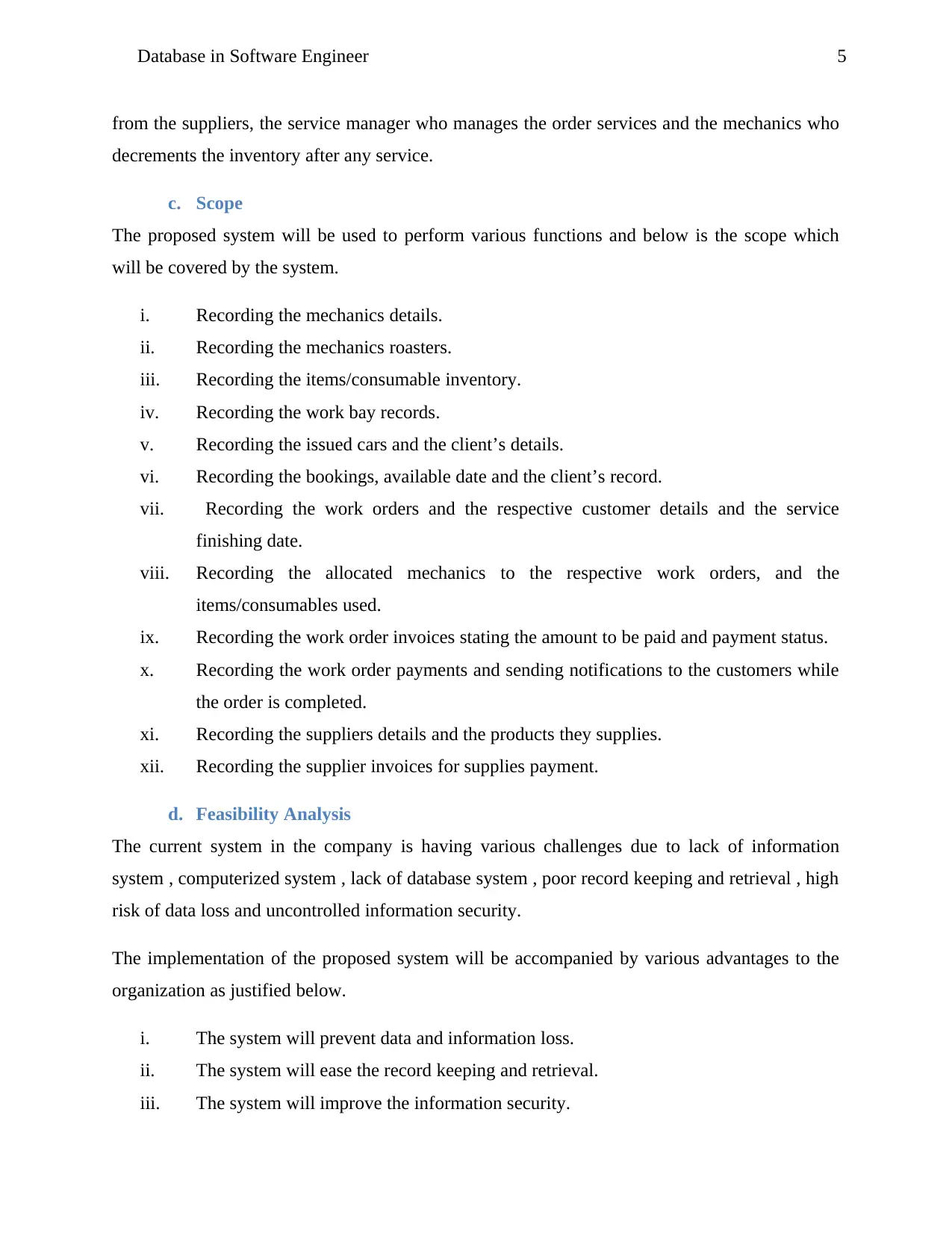
c. Scope
The proposed system will be used to perform various functions and below is the scope which
will be covered by the system.
i. Recording the mechanics details.
ii. Recording the mechanics roasters.
iii. Recording the items/consumable inventory.
iv. Recording the work bay records.
v. Recording the issued cars and the client’s details.
vi. Recording the bookings, available date and the client’s record.
vii. Recording the work orders and the respective customer details and the service
finishing date.
viii. Recording the allocated mechanics to the respective work orders, and the
items/consumables used.
ix. Recording the work order invoices stating the amount to be paid and payment status.
x. Recording the work order payments and sending notifications to the customers while
the order is completed.
xi. Recording the suppliers details and the products they supplies.
xii. Recording the supplier invoices for supplies payment.
d. Feasibility Analysis
The current system in the company is having various challenges due to lack of information
system , computerized system , lack of database system , poor record keeping and retrieval , high
risk of data loss and uncontrolled information security.
The implementation of the proposed system will be accompanied by various advantages to the
organization as justified below.
i. The system will prevent data and information loss.
ii. The system will ease the record keeping and retrieval.
iii. The system will improve the information security.
from the suppliers, the service manager who manages the order services and the mechanics who
decrements the inventory after any service.
c. Scope
The proposed system will be used to perform various functions and below is the scope which
will be covered by the system.
i. Recording the mechanics details.
ii. Recording the mechanics roasters.
iii. Recording the items/consumable inventory.
iv. Recording the work bay records.
v. Recording the issued cars and the client’s details.
vi. Recording the bookings, available date and the client’s record.
vii. Recording the work orders and the respective customer details and the service
finishing date.
viii. Recording the allocated mechanics to the respective work orders, and the
items/consumables used.
ix. Recording the work order invoices stating the amount to be paid and payment status.
x. Recording the work order payments and sending notifications to the customers while
the order is completed.
xi. Recording the suppliers details and the products they supplies.
xii. Recording the supplier invoices for supplies payment.
d. Feasibility Analysis
The current system in the company is having various challenges due to lack of information
system , computerized system , lack of database system , poor record keeping and retrieval , high
risk of data loss and uncontrolled information security.
The implementation of the proposed system will be accompanied by various advantages to the
organization as justified below.
i. The system will prevent data and information loss.
ii. The system will ease the record keeping and retrieval.
iii. The system will improve the information security.
6Database in Software Engineer
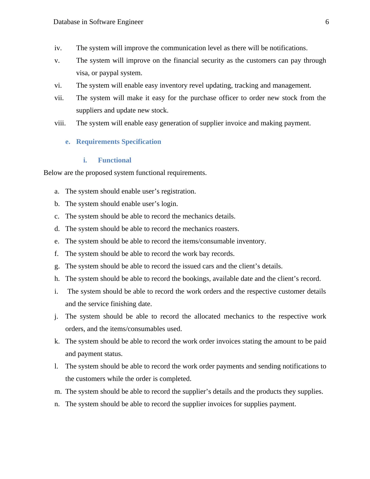
iv. The system will improve the communication level as there will be notifications.
v. The system will improve on the financial security as the customers can pay through
visa, or paypal system.
vi. The system will enable easy inventory revel updating, tracking and management.
vii. The system will make it easy for the purchase officer to order new stock from the
suppliers and update new stock.
viii. The system will enable easy generation of supplier invoice and making payment.
e. Requirements Specification
i. Functional
Below are the proposed system functional requirements.
a. The system should enable user’s registration.
b. The system should enable user’s login.
c. The system should be able to record the mechanics details.
d. The system should be able to record the mechanics roasters.
e. The system should be able to record the items/consumable inventory.
f. The system should be able to record the work bay records.
g. The system should be able to record the issued cars and the client’s details.
h. The system should be able to record the bookings, available date and the client’s record.
i. The system should be able to record the work orders and the respective customer details
and the service finishing date.
j. The system should be able to record the allocated mechanics to the respective work
orders, and the items/consumables used.
k. The system should be able to record the work order invoices stating the amount to be paid
and payment status.
l. The system should be able to record the work order payments and sending notifications to
the customers while the order is completed.
m. The system should be able to record the supplier’s details and the products they supplies.
n. The system should be able to record the supplier invoices for supplies payment.
⊘ This is a preview!⊘
Do you want full access?
Subscribe today to unlock all pages.
Trusted by 1+ million students worldwide

7Database in Software Engineer
MOTORS INFORMATION SYSTEM USE CASE DIAGRAM
User registration
User login
Recording the mechanics details
Recording the mechanics roasters
Service manager
Mechanic
Searching available work orders
ii. Non-Functional
Below are some of non-functional requirements.
i. The user of the system should be registered.
ii. The system should be highly available to enable users to use it any time.
iii. The system should have high security level to ensure all records are safe.
iv. The system should have fast loading and response time to avoid delays in service
delivery.
f. Assumptions/ Constraints
Below are the various system design assumptions.
i. The company will have installed computer system before system installation.
ii. The company will have installed a network to all departments before the system
installation.
iii. The company staffs will be fully trained on how to use the system.
iv. The system will be compatible with any computer hardware.
v. The computer systems will be installed with windows 7/8/10 operating system.
vi. The computer system will have a hard disk of 250 GB and above.
vii. The computer system will have an Intel duo-core processor type with processing
speed of 2.4 GHZ and above.
viii. The computer systems will be installed anti-malware software applications before
installation of the system.
g. Use Cases (from functional requirements) (at least 4 per group)
i. Use Case Diagrams
a. First use case diagram.
Paraphrase This Document
Need a fresh take? Get an instant paraphrase of this document with our AI Paraphraser
8Database in Software Engineer
Mechanic
Recording the issued cars details
MOTORS INFORMATION SYSTEM USE CASE DIAGRAM
User registration
User login
Recording the items/consumable inventory
Recording the work bay details
Service manager
Service assistant
Mechanic
Recording the work order invoices details
Recording the work orders details
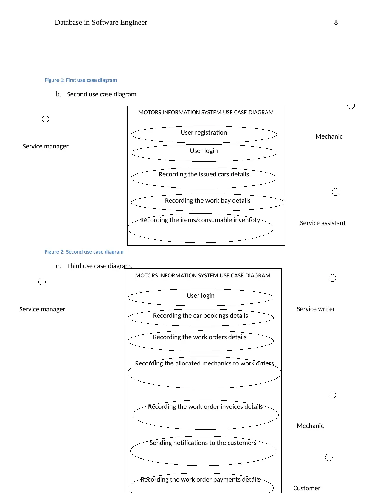
MOTORS INFORMATION SYSTEM USE CASE DIAGRAM
User login
Recording the car bookings details
Recording the allocated mechanics to work orders
Service manager Service writer
Recording the work order payments details
Sending notifications to the customers
Customer
Figure 1: First use case diagram
b. Second use case diagram.
Figure 2: Second use case diagram
c. Third use case diagram.
Mechanic
Recording the issued cars details
MOTORS INFORMATION SYSTEM USE CASE DIAGRAM
User registration
User login
Recording the items/consumable inventory
Recording the work bay details
Service manager
Service assistant
Mechanic
Recording the work order invoices details
Recording the work orders details
MOTORS INFORMATION SYSTEM USE CASE DIAGRAM
User login
Recording the car bookings details
Recording the allocated mechanics to work orders
Service manager Service writer
Recording the work order payments details
Sending notifications to the customers
Customer
Figure 1: First use case diagram
b. Second use case diagram.
Figure 2: Second use case diagram
c. Third use case diagram.
9Database in Software Engineer
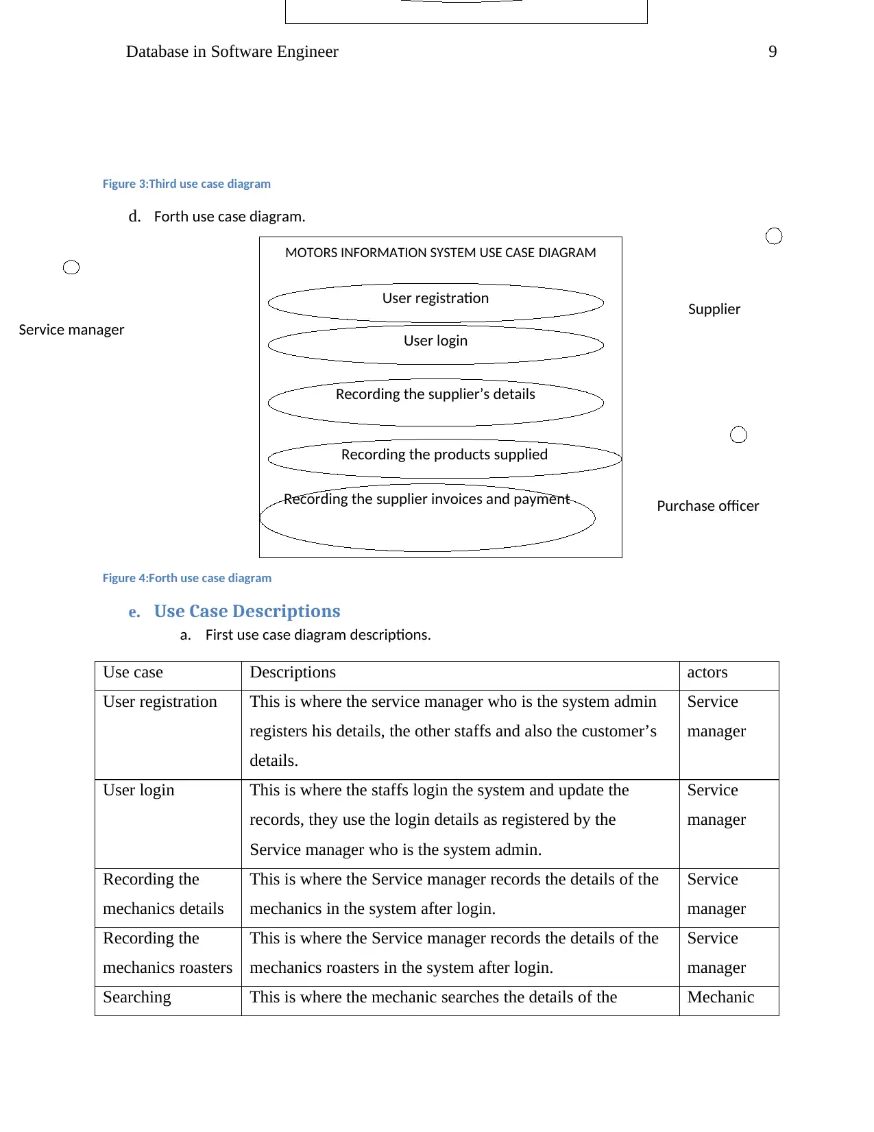
Recording the supplier’s details
MOTORS INFORMATION SYSTEM USE CASE DIAGRAM
User registration
User login
Recording the supplier invoices and payment
Recording the products supplied
Service manager
Purchase officer
Figure 3:Third use case diagram
d. Forth use case diagram.
Figure 4:Forth use case diagram
e. Use Case Descriptions
a. First use case diagram descriptions.
Use case Descriptions actors
User registration This is where the service manager who is the system admin
registers his details, the other staffs and also the customer’s
details.
Service
manager
User login This is where the staffs login the system and update the
records, they use the login details as registered by the
Service manager who is the system admin.
Service
manager
Recording the
mechanics details
This is where the Service manager records the details of the
mechanics in the system after login.
Service
manager
Recording the
mechanics roasters
This is where the Service manager records the details of the
mechanics roasters in the system after login.
Service
manager
Searching This is where the mechanic searches the details of the Mechanic
Supplier
⊘ This is a preview!⊘
Do you want full access?
Subscribe today to unlock all pages.
Trusted by 1+ million students worldwide
10Database in Software Engineer
available work
orders
pending work orders using the system after login.
Table 1:First use case diagram descriptions
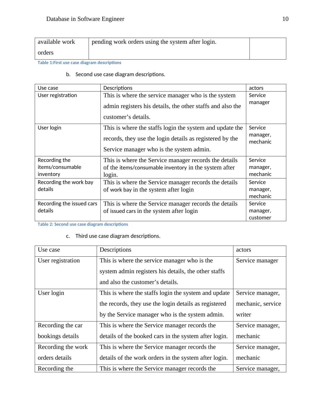
b. Second use case diagram descriptions.
Use case Descriptions actors
User registration This is where the service manager who is the system
admin registers his details, the other staffs and also the
customer’s details.
Service
manager
User login This is where the staffs login the system and update the
records, they use the login details as registered by the
Service manager who is the system admin.
Service
manager,
mechanic
Recording the
items/consumable
inventory
This is where the Service manager records the details
of the items/consumable inventory in the system after
login.
Service
manager,
mechanic
Recording the work bay
details
This is where the Service manager records the details
of work bay in the system after login
Service
manager,
mechanic
Recording the issued cars
details
This is where the Service manager records the details
of issued cars in the system after login
Service
manager,
customer
Table 2: Second use case diagram descriptions
c. Third use case diagram descriptions.
Use case Descriptions actors
User registration This is where the service manager who is the
system admin registers his details, the other staffs
and also the customer’s details.
Service manager
User login This is where the staffs login the system and update
the records, they use the login details as registered
by the Service manager who is the system admin.
Service manager,
mechanic, service
writer
Recording the car
bookings details
This is where the Service manager records the
details of the booked cars in the system after login.
Service manager,
mechanic
Recording the work
orders details
This is where the Service manager records the
details of the work orders in the system after login.
Service manager,
mechanic
Recording the This is where the Service manager records the Service manager,
available work
orders
pending work orders using the system after login.
Table 1:First use case diagram descriptions
b. Second use case diagram descriptions.
Use case Descriptions actors
User registration This is where the service manager who is the system
admin registers his details, the other staffs and also the
customer’s details.
Service
manager
User login This is where the staffs login the system and update the
records, they use the login details as registered by the
Service manager who is the system admin.
Service
manager,
mechanic
Recording the
items/consumable
inventory
This is where the Service manager records the details
of the items/consumable inventory in the system after
login.
Service
manager,
mechanic
Recording the work bay
details
This is where the Service manager records the details
of work bay in the system after login
Service
manager,
mechanic
Recording the issued cars
details
This is where the Service manager records the details
of issued cars in the system after login
Service
manager,
customer
Table 2: Second use case diagram descriptions
c. Third use case diagram descriptions.
Use case Descriptions actors
User registration This is where the service manager who is the
system admin registers his details, the other staffs
and also the customer’s details.
Service manager
User login This is where the staffs login the system and update
the records, they use the login details as registered
by the Service manager who is the system admin.
Service manager,
mechanic, service
writer
Recording the car
bookings details
This is where the Service manager records the
details of the booked cars in the system after login.
Service manager,
mechanic
Recording the work
orders details
This is where the Service manager records the
details of the work orders in the system after login.
Service manager,
mechanic
Recording the This is where the Service manager records the Service manager,
Paraphrase This Document
Need a fresh take? Get an instant paraphrase of this document with our AI Paraphraser
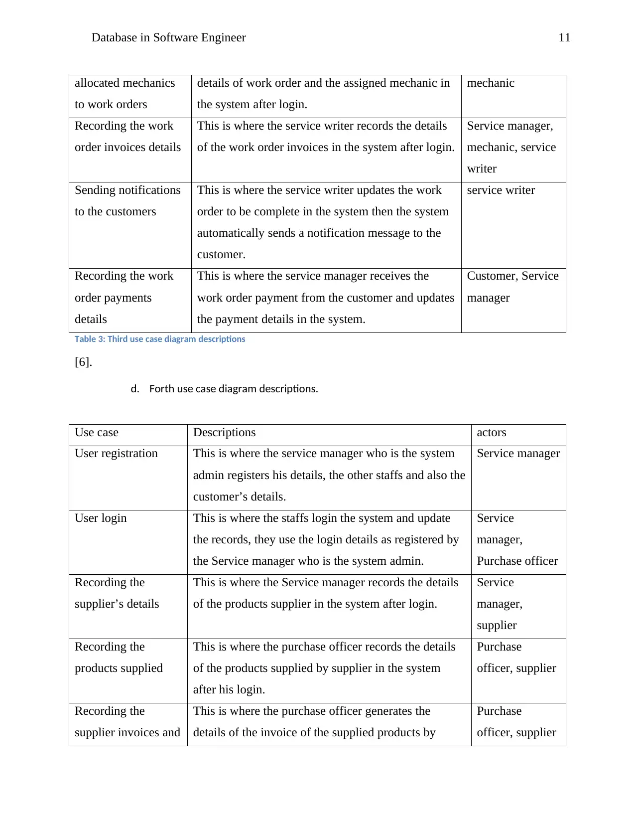
11Database in Software Engineer
allocated mechanics
to work orders
details of work order and the assigned mechanic in
the system after login.
mechanic
Recording the work
order invoices details
This is where the service writer records the details
of the work order invoices in the system after login.
Service manager,
mechanic, service
writer
Sending notifications
to the customers
This is where the service writer updates the work
order to be complete in the system then the system
automatically sends a notification message to the
customer.
service writer
Recording the work
order payments
details
This is where the service manager receives the
work order payment from the customer and updates
the payment details in the system.
Customer, Service
manager
Table 3: Third use case diagram descriptions
[6].
d. Forth use case diagram descriptions.
Use case Descriptions actors
User registration This is where the service manager who is the system
admin registers his details, the other staffs and also the
customer’s details.
Service manager
User login This is where the staffs login the system and update
the records, they use the login details as registered by
the Service manager who is the system admin.
Service
manager,
Purchase officer
Recording the
supplier’s details
This is where the Service manager records the details
of the products supplier in the system after login.
Service
manager,
supplier
Recording the
products supplied
This is where the purchase officer records the details
of the products supplied by supplier in the system
after his login.
Purchase
officer, supplier
Recording the
supplier invoices and
This is where the purchase officer generates the
details of the invoice of the supplied products by
Purchase
officer, supplier
12Database in Software Engineer
payment particular customer for them to be paid.
Table 4: Forth use case diagram descriptions
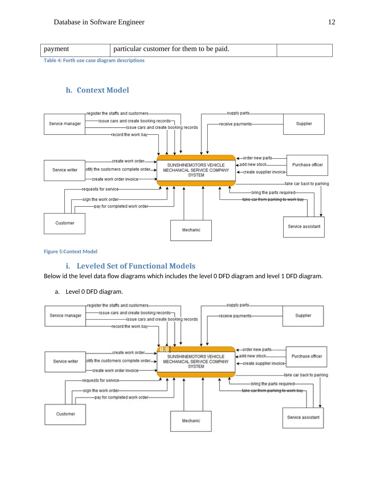
h. Context Model
Figure 5:Context Model
i. Leveled Set of Functional Models
Below id the level data flow diagrams which includes the level 0 DFD diagram and level 1 DFD diagram.
a. Level 0 DFD diagram.
payment particular customer for them to be paid.
Table 4: Forth use case diagram descriptions
h. Context Model
Figure 5:Context Model
i. Leveled Set of Functional Models
Below id the level data flow diagrams which includes the level 0 DFD diagram and level 1 DFD diagram.
a. Level 0 DFD diagram.
⊘ This is a preview!⊘
Do you want full access?
Subscribe today to unlock all pages.
Trusted by 1+ million students worldwide
1 out of 27
Related Documents


Your All-in-One AI-Powered Toolkit for Academic Success.
+13062052269
info@desklib.com
Available 24*7 on WhatsApp / Email
![[object Object]](/_next/static/media/star-bottom.7253800d.svg)
Unlock your academic potential
Copyright © 2020–2026 A2Z Services. All Rights Reserved. Developed and managed by ZUCOL.