DC Circuits: Engineering Science Calculation and Problem Solving
VerifiedAdded on 2023/04/21
|10
|1547
|483
Homework Assignment
AI Summary
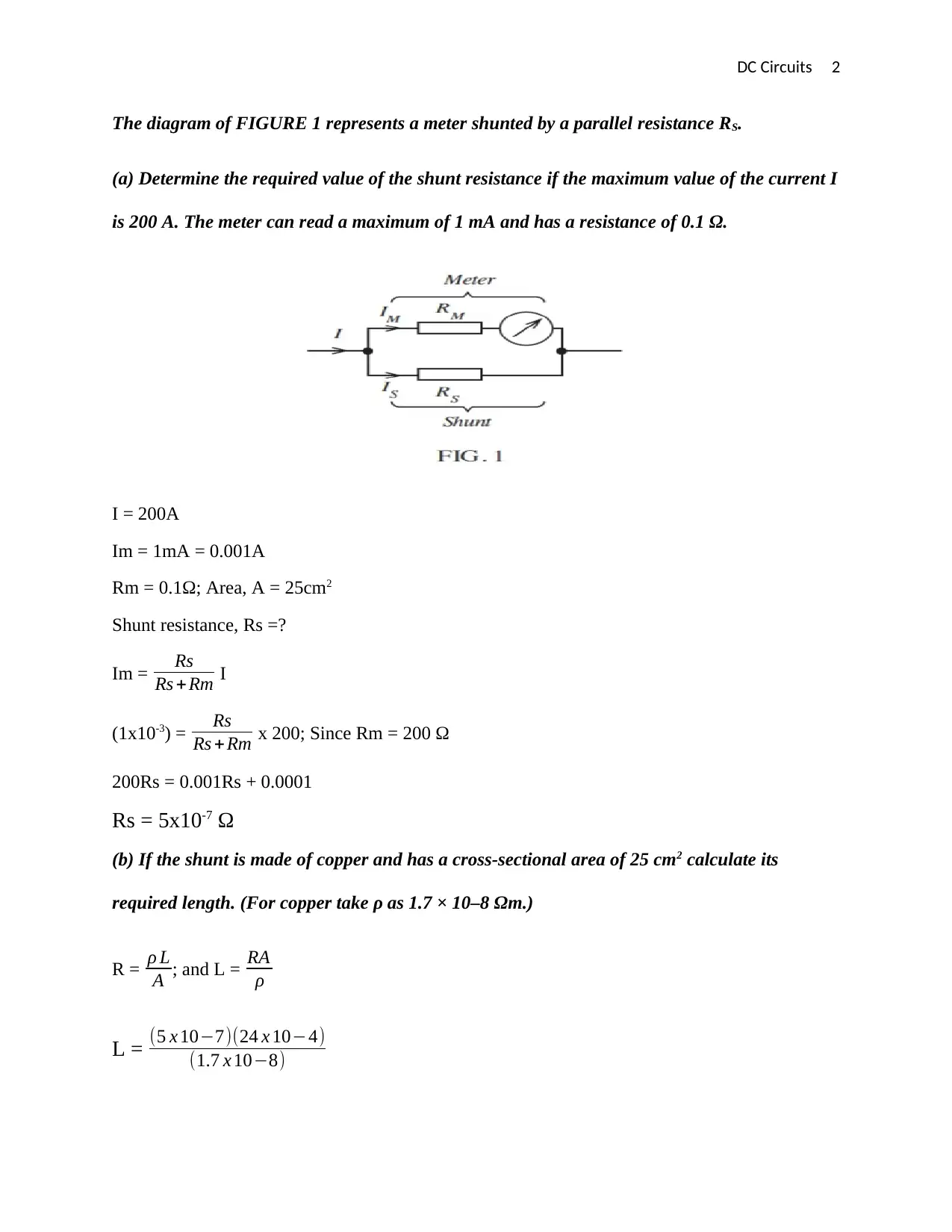
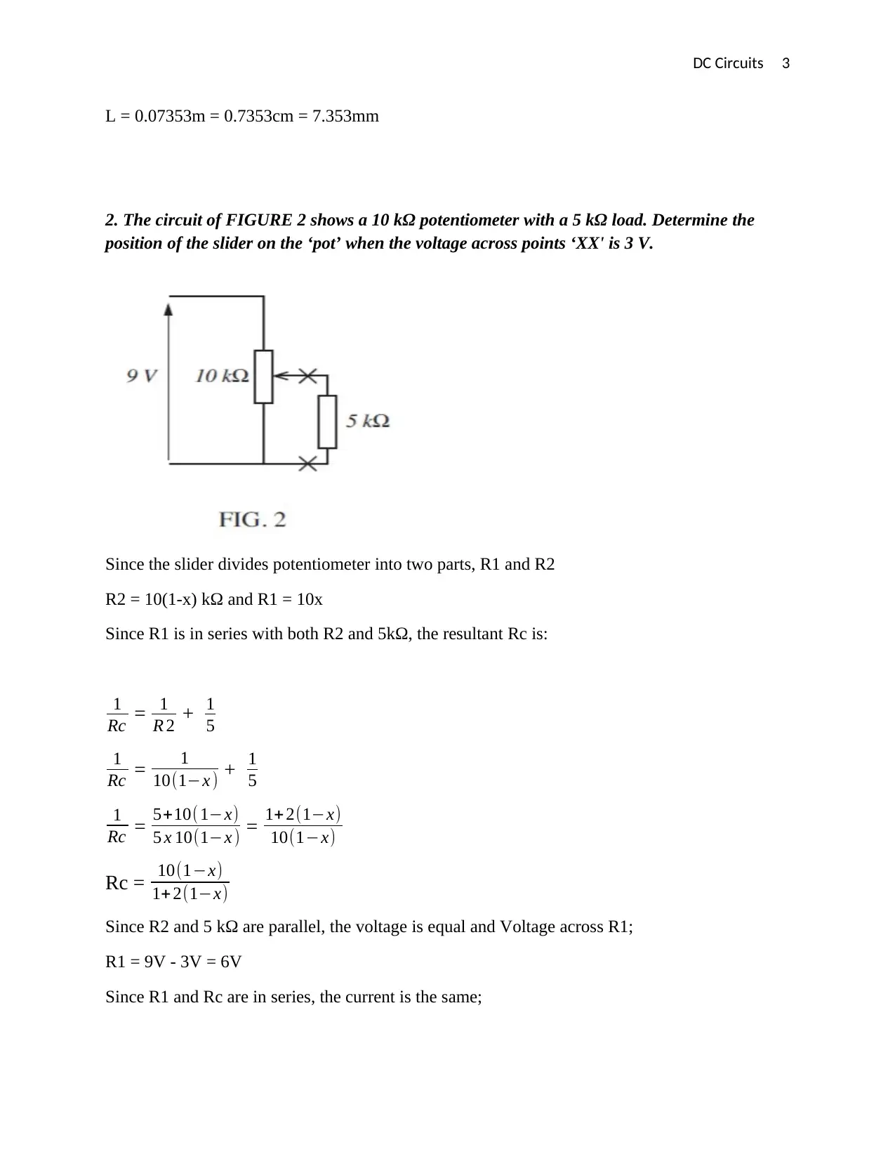
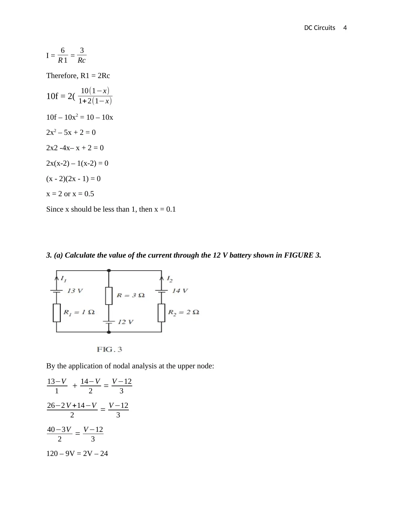
This document presents a solved assignment focused on DC circuits, covering a range of problems and calculations relevant to electrical engineering. It includes determining shunt resistance for a meter, analyzing a potentiometer circuit, applying nodal analysis to find current and power dissipation, calculating the time over which magnetic flux changes, determining the current in a conductor within a magnetic field, estimating the radius of plates in a multi-plate variable capacitor, and analyzing the time constant and voltage drops in an inductor-resistor circuit. The solutions provide step-by-step explanations and calculations, making it a valuable resource for students studying DC circuits and electromagnetic principles. Desklib provides solved assignments and past papers for students.
1 out of 10
Related Documents


Your All-in-One AI-Powered Toolkit for Academic Success.
+13062052269
info@desklib.com
Available 24*7 on WhatsApp / Email
![[object Object]](/_next/static/media/star-bottom.7253800d.svg)
Copyright © 2020–2025 A2Z Services. All Rights Reserved. Developed and managed by ZUCOL.