Faculty of Technology: DC Motor Modelling and Control Report
VerifiedAdded on 2023/05/30
|12
|1248
|75
Report
AI Summary
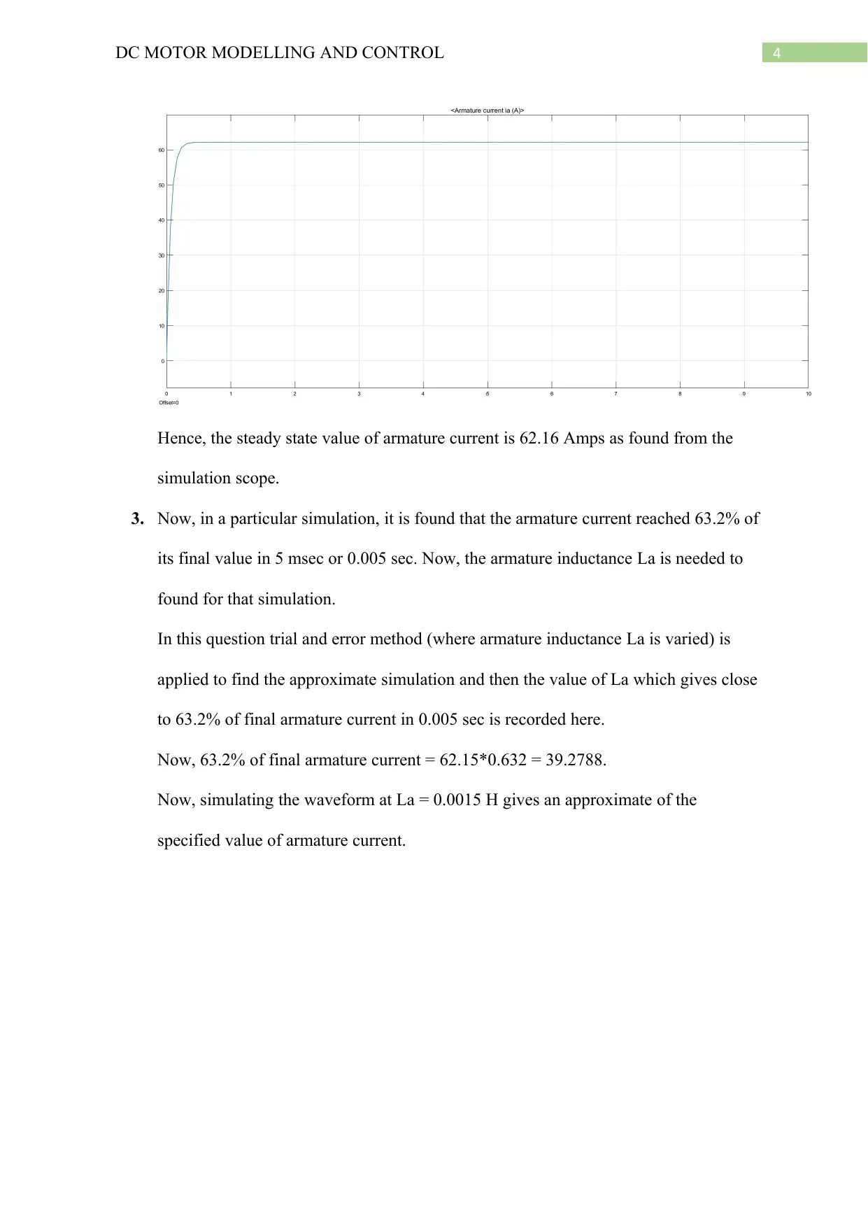
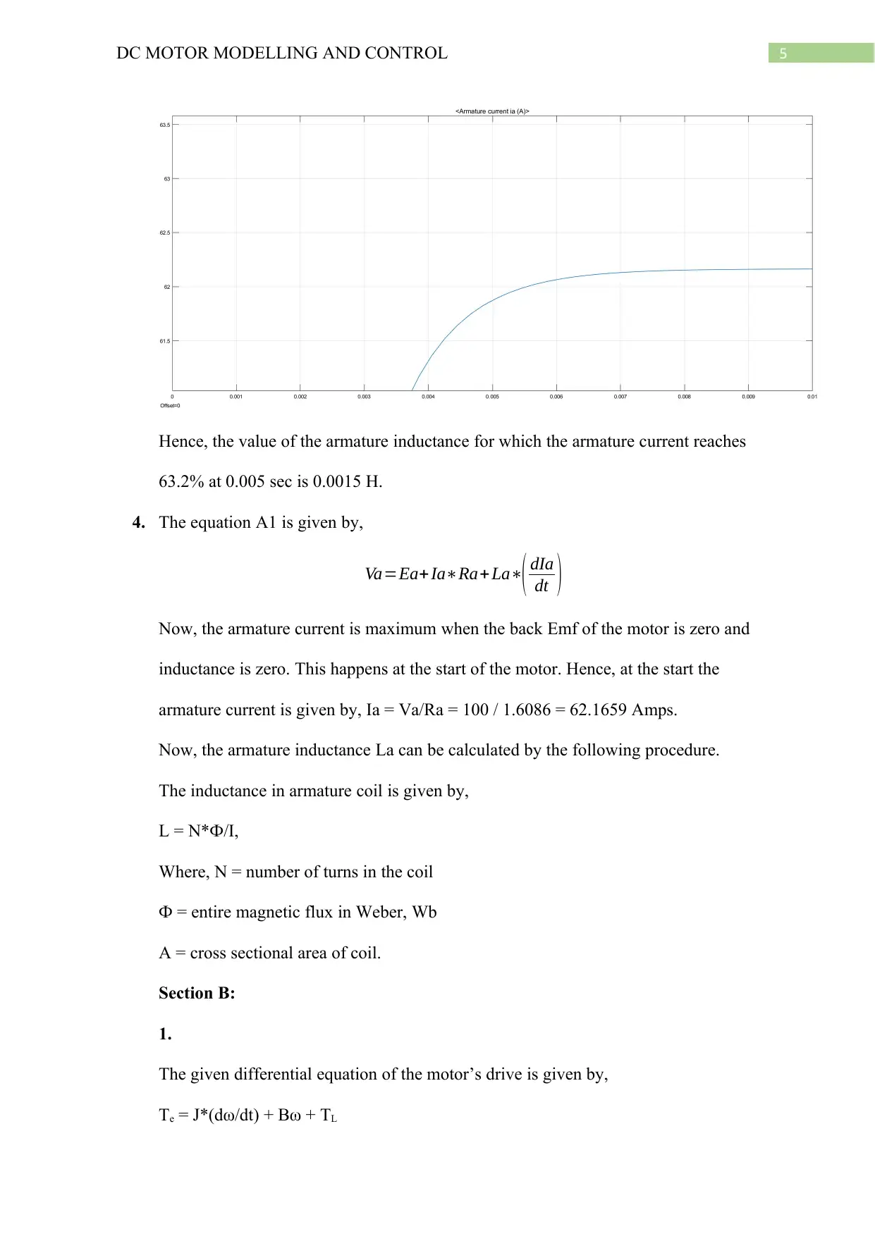
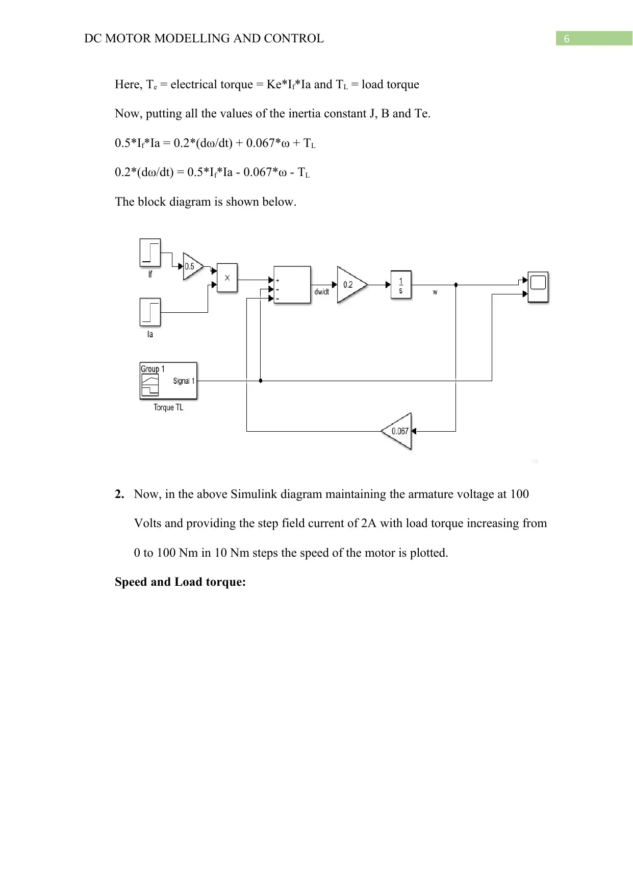
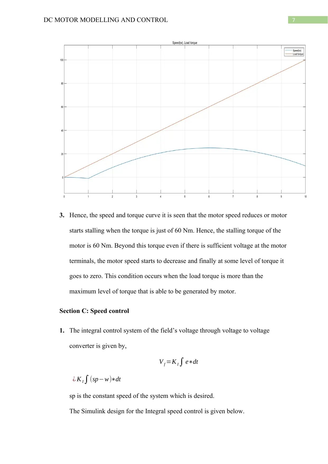
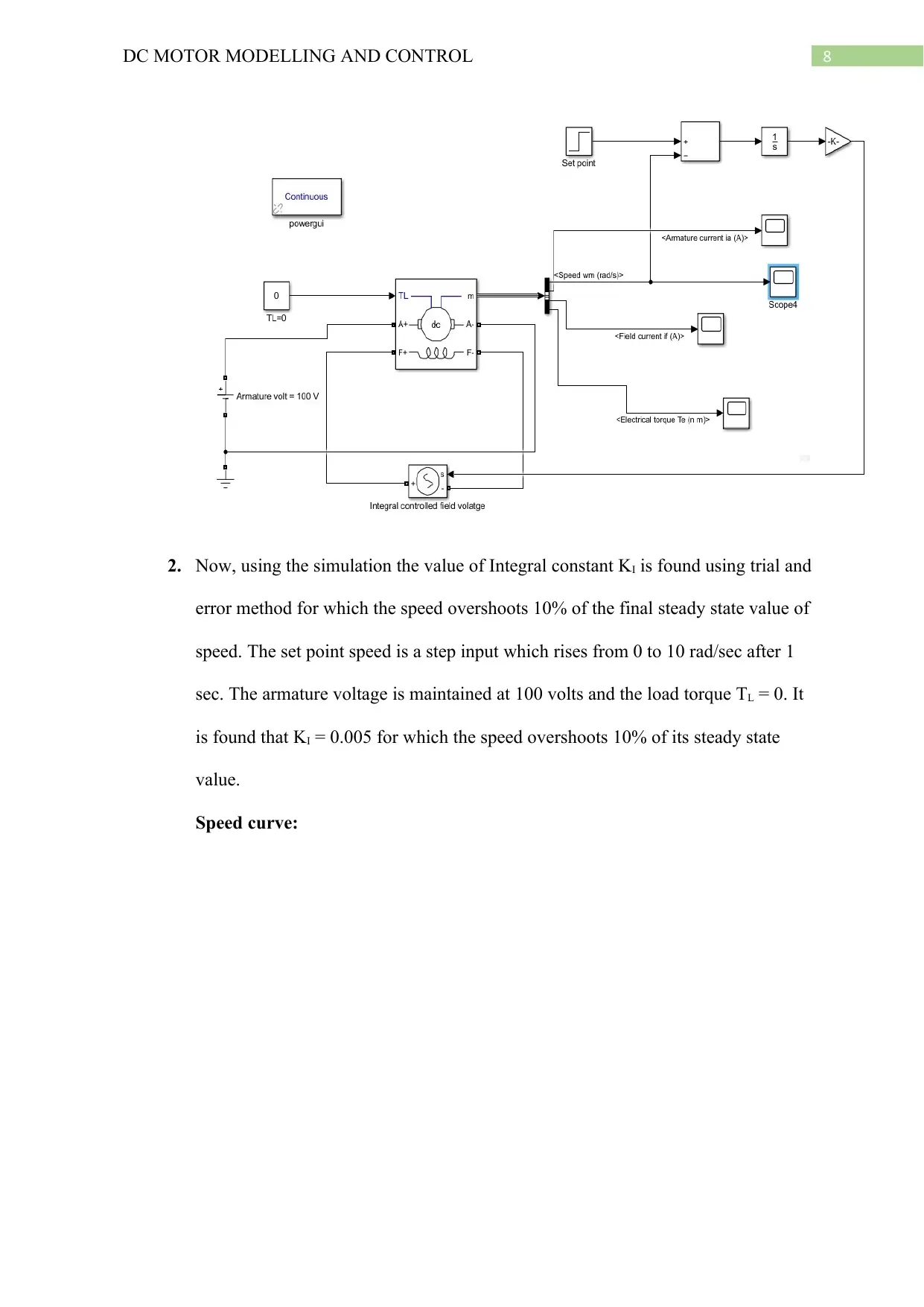
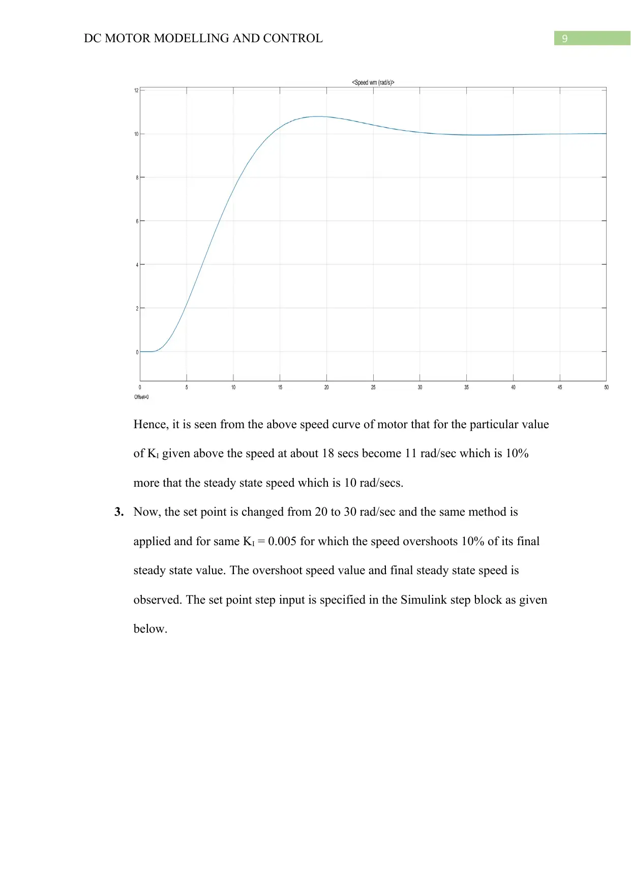
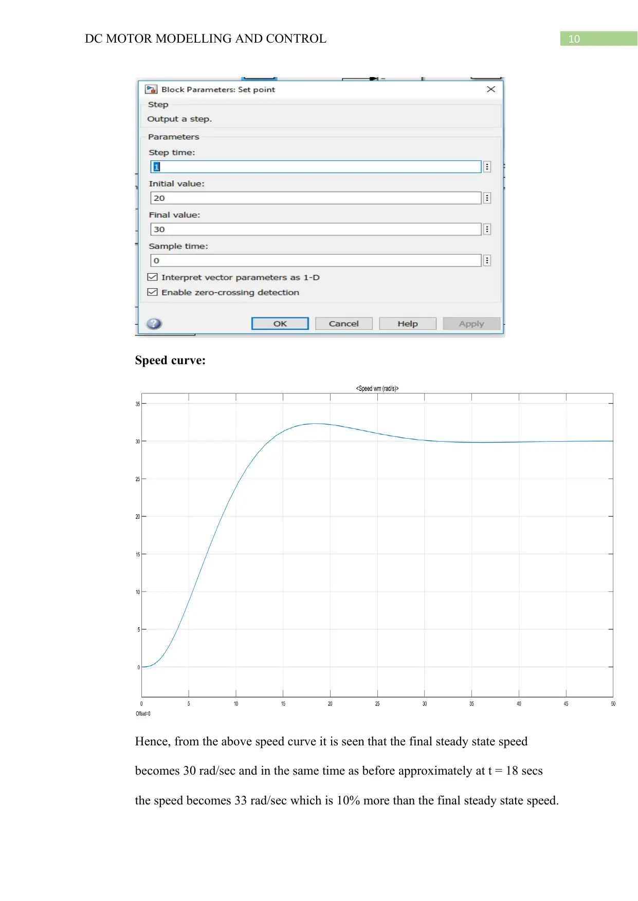
This report presents a detailed analysis of DC motor modeling and control, encompassing three key sections. Section A focuses on DC motor modeling, including the equivalent circuit diagram, calculations of armature resistance, and the simulation of back EMF and armature current using Simulink. The report determines the armature inductance based on the motor's response to a voltage step. Section B explores the motor's drive characteristics, including the differential equation governing the motor's behavior, and the determination of stalling torque through Simulink simulations. Finally, Section C investigates speed control using an integral control system, including the design of the control system, and the determination of the integral constant (KI) to achieve a desired speed overshoot. The report concludes with the analysis of speed curves under varying set points, demonstrating the effectiveness of the control strategy. The assignment is a coursework report for the Faculty of Technology EAT216 CAE module.

1 out of 12


Your All-in-One AI-Powered Toolkit for Academic Success.
+13062052269
info@desklib.com
Available 24*7 on WhatsApp / Email
![[object Object]](/_next/static/media/star-bottom.7253800d.svg)
Copyright © 2020–2026 A2Z Services. All Rights Reserved. Developed and managed by ZUCOL.