Building Services Applications: Ventilation, Heating Systems, Lighting
VerifiedAdded on 2023/04/25
|11
|1859
|141
AI Summary
This document covers the design and calculation of natural and mechanical ventilation, heating systems, and electric lighting in building services applications. It includes measures to improve summer time temperatures, duct design, and lighting strategies. The document also provides specifications for fittings and more.
Contribute Materials
Your contribution can guide someone’s learning journey. Share your
documents today.
BUILDING SERVICES
APPLICATIONS
1
APPLICATIONS
1
Secure Best Marks with AI Grader
Need help grading? Try our AI Grader for instant feedback on your assignments.
Table of Contents
Questions A – Natural and Mechanical Ventilation..........................................................................3
Calculation of Heat flow..................................................................................................................3
Measures to improve the control of summer time temperatures..................................................4
Design of Duct..................................................................................................................................4
Schematic of a duct..........................................................................................................................5
Duct sizes for the system.................................................................................................................5
Pressure drop through the system..................................................................................................6
Questions B – Heating Systems...........................................................................................................6
Calculation of heating coil load......................................................................................................6
Schematic of Heater.........................................................................................................................7
Question C – Lighting.........................................................................................................................7
User requirement specification for the building............................................................................7
Electric lighting of the composite lab design.................................................................................8
Specification sheet for the types of fittings:...................................................................................8
2
Questions A – Natural and Mechanical Ventilation
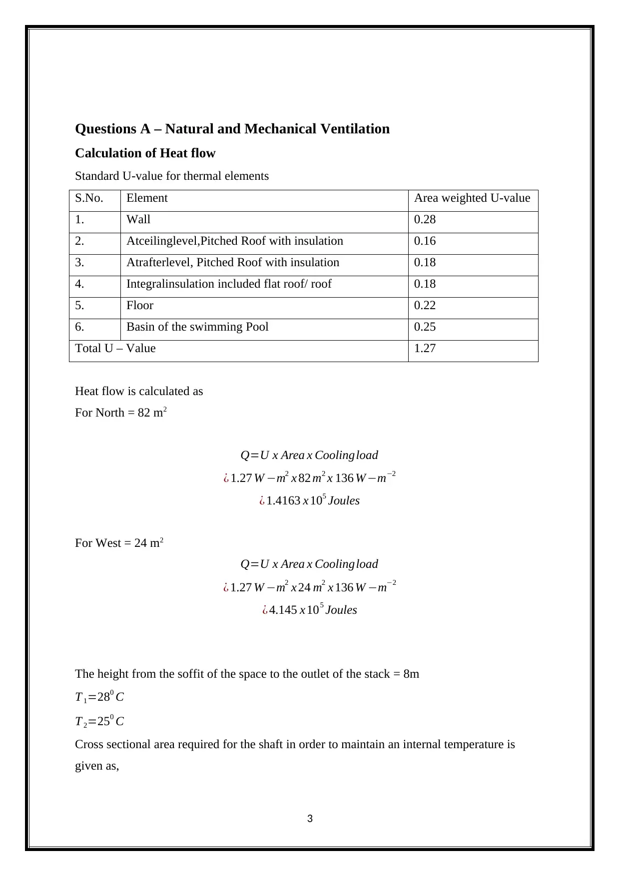
Calculation of Heat flow
Standard U-value for thermal elements
S.No. Element Area weighted U-value
1. Wall 0.28
2. Atceilinglevel,Pitched Roof with insulation 0.16
3. Atrafterlevel, Pitched Roof with insulation 0.18
4. Integralinsulation included flat roof/ roof 0.18
5. Floor 0.22
6. Basin of the swimming Pool 0.25
Total U – Value 1.27
Heat flow is calculated as
For North = 82 m2
Q=U x Area x Coolingload
¿ 1.27 W −m2 x 82 m2 x 136 W −m−2
¿ 1.4163 x 10⁵ Joules
For West = 24 m2
Q=U x Area x Coolingload
¿ 1.27 W −m2 x 24 m2 x 136 W −m−2
¿ 4.145 x 10⁵ Joules
The height from the soffit of the space to the outlet of the stack = 8m
T 1=280 C
T 2=250 C
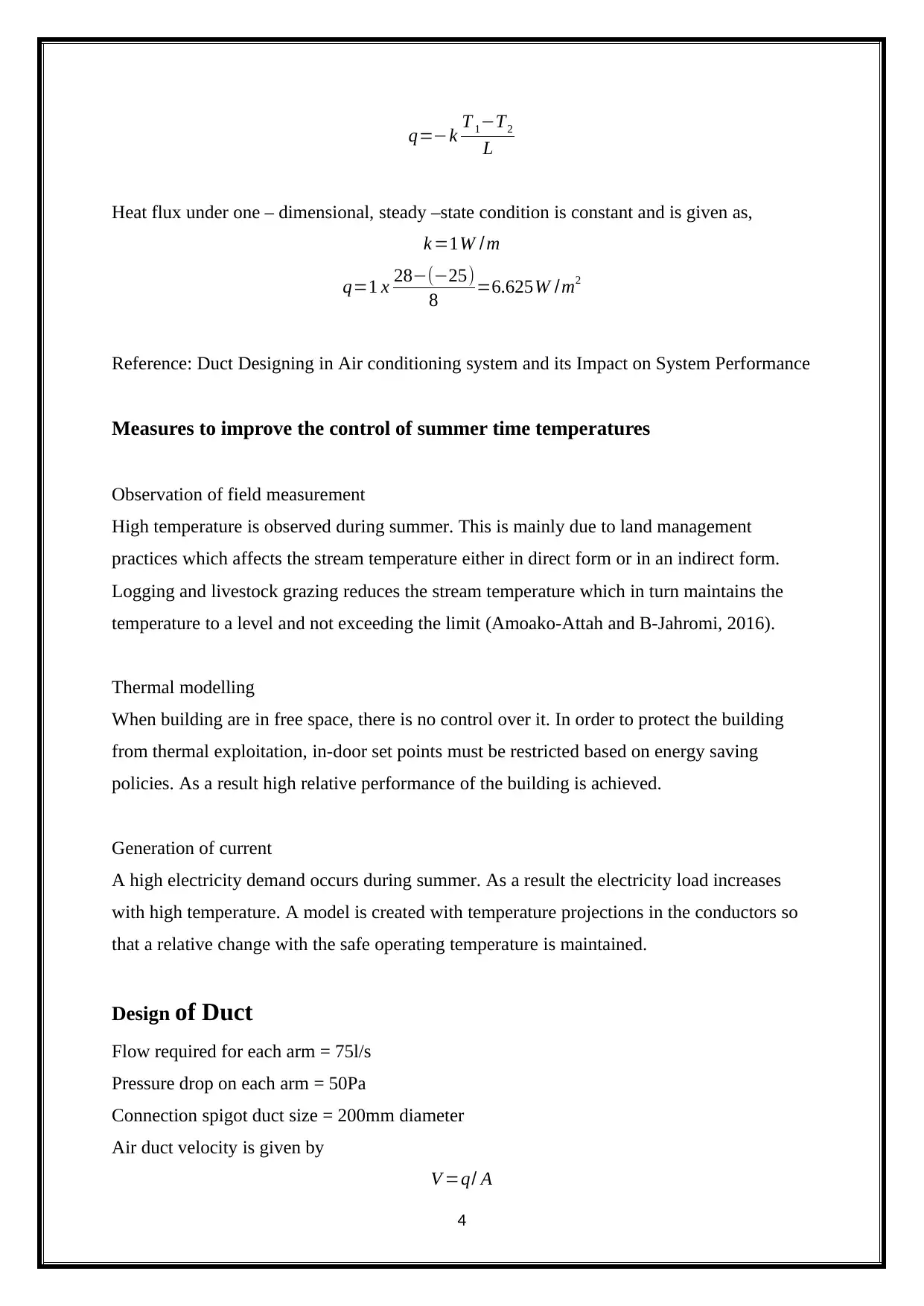
Cross sectional area required for the shaft in order to maintain an internal temperature is
given as,
3
q=−k T 1−T2
L
Heat flux under one – dimensional, steady –state condition is constant and is given as,
k =1W /m
q=1 x 28−(−25)
8 =6.625W /m2
Reference: Duct Designing in Air conditioning system and its Impact on System Performance
Measures to improve the control of summer time temperatures
Observation of field measurement
High temperature is observed during summer. This is mainly due to land management
practices which affects the stream temperature either in direct form or in an indirect form.
Logging and livestock grazing reduces the stream temperature which in turn maintains the
temperature to a level and not exceeding the limit (Amoako-Attah and B-Jahromi, 2016).
Thermal modelling
When building are in free space, there is no control over it. In order to protect the building
from thermal exploitation, in-door set points must be restricted based on energy saving
policies. As a result high relative performance of the building is achieved.
Generation of current
A high electricity demand occurs during summer. As a result the electricity load increases
with high temperature. A model is created with temperature projections in the conductors so
that a relative change with the safe operating temperature is maintained.
Design of Duct
Flow required for each arm = 75l/s
Pressure drop on each arm = 50Pa
Connection spigot duct size = 200mm diameter
Air duct velocity is given by
V =q/ A
4
Secure Best Marks with AI Grader
Need help grading? Try our AI Grader for instant feedback on your assignments.
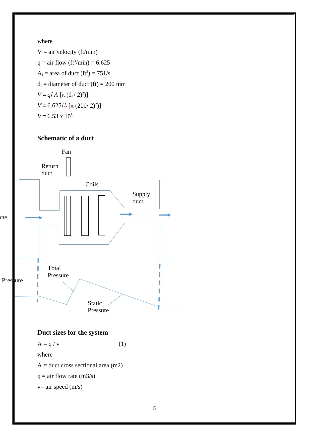
Pressure
one
Return
duct
Supply
duct
Total
Pressure
Static
Pressure
Coils
Fan
where
V = air velocity (ft/min)
q = air flow (ft3/min) = 6.625
Ai = area of duct (ft2) = 751/s
df = diameter of duct (ft) = 200 mm
V =q/ A [π (df / 2)2)]
V =6.625/ ¿ [π (200/ 2)2)]
V =6.53 x 10⁵
Schematic of a duct
Duct sizes for the system
A = q / v (1)
where
A = duct cross sectional area (m2)
q = air flow rate (m3/s)
v= air speed (m/s)
5
A = 6.625 / 6.53 x 105 = 1.01 x 10⁻⁵m/s
Pressure drop through the system
Pdrop = (V/200)2 = (6.625 / 200) 2 = 1.09 x 10⁻⁴ watts
Reference:Design Of Duct For A Three Storey Retail Shop
Questions B – Heating Systems
Calculation of heating coil load
Heating load calculations area unit allotted to estimate the warmth loss from the building in
winter therefore on gain neededheating capacities. Ordinarily throughout winter months the
height heating load happens beforesunrise and therefore
the outside conditions don't vary considerably throughout the winter season.Additionally,
internal heat sources like occupants or appliances area unit helpful as they compensate a
number of the warmthlosses. As a result, normally, the warmth load calculations area
unit allotted presumptuous steady state conditions (no radiation and
steady outside conditions) and neglecting internal heat sources. This is a
straightforward however conservative approach that results in slight overestimation of the
heating capability. For a lot of correct estimation of heating hundreds, one has got to take into
the thermal capability of the walls and internal heat sources that makes the matter a lot
of sophisticated. The laboratory itself is heated by warming panels, suspended at high level.
The adjacent areas are heated by fan coil units.
For any building there exists a balance purpose at that the radiation and internal heat
generation rate specifically balance the warmth losses from the building. Therefore, atthe
balancedcondition the wise heat balance equationis,
Qsolar + Qint = UA (Tin – Tout)
where,
UA refers to heat transfer constant and warmth transfer space of the building.
Tin refers to the temperature of the indoor.
Tout denotes the temperatureof the outdoor (Gu,Jung and Lee, 2012). From the above
mentioned equation, at balancedcondition the surface temperatureis,
Tout,bal = Tin – (Qsolar+Qint)/ UA
6
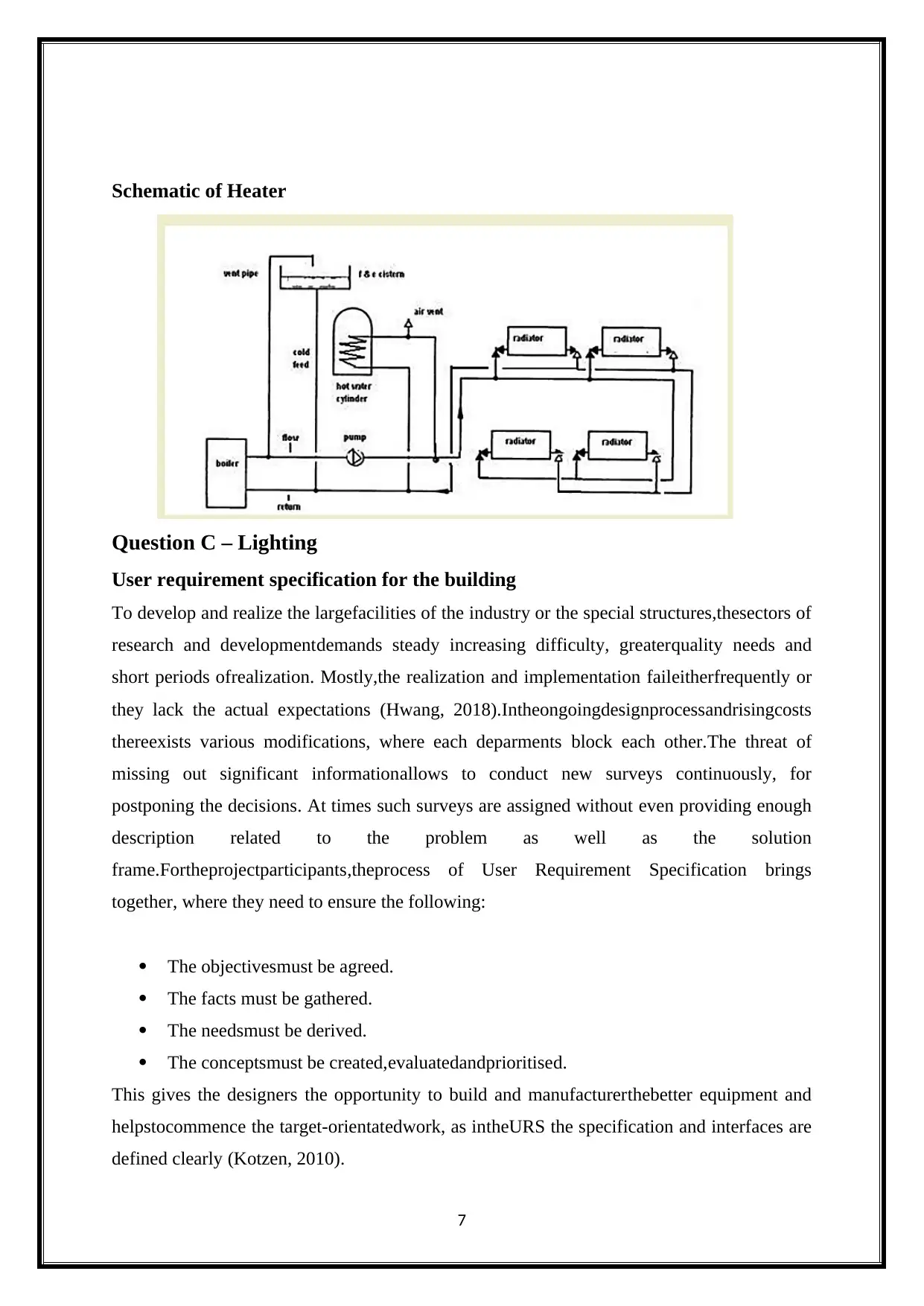
Schematic of Heater
Question C – Lighting
User requirement specification for the building
To develop and realize the largefacilities of the industry or the special structures,thesectors of
research and developmentdemands steady increasing difficulty, greaterquality needs and
short periods ofrealization. Mostly,the realization and implementation faileitherfrequently or
they lack the actual expectations (Hwang, 2018).Intheongoingdesignprocessandrisingcosts
thereexists various modifications, where each deparments block each other.The threat of
missing out significant informationallows to conduct new surveys continuously, for
postponing the decisions. At times such surveys are assigned without even providing enough
description related to the problem as well as the solution
frame.Fortheprojectparticipants,theprocess of User Requirement Specification brings
together, where they need to ensure the following:
The objectivesmust be agreed.
The facts must be gathered.
The needsmust be derived.
The conceptsmust be created,evaluatedandprioritised.
This gives the designers the opportunity to build and manufacturerthebetter equipment and
helpstocommence the target-orientatedwork, as intheURS the specification and interfaces are
defined clearly (Kotzen, 2010).
7
Paraphrase This Document
Need a fresh take? Get an instant paraphrase of this document with our AI Paraphraser
Electric lighting of the composite lab design
In the last three years,forbothoverheadandtasklighting,the use of LED lights has increased,
due to the improvements in the labs with humanisticfeatures. Despite the fact that the LED
lighting's cost is higher when compared to the T5 fluorescent fixture,the LED lighting is
preferred as it provides cost savings for a long-term,as it contains high efficiency which
outweighs the initial costsof the LED lights (Raynham, 2012).The LED technology's
technical advances and its fixtures have helped to open new lab applications. Moreover,in the
last three years,ago and there is improvement in the technology's colourring.On the other
hand, the number of vendors for LED lighting has increased and providesthem with viable
optionswhich keeps them highly competitive. There are different strategies for lighting in the
lab.
Different strategies for Electric lighting in the lab
1st Strategy: Always the electric lighting must be designed as a supplement to daylighting.
2nd Strategy: Utilize direct-indirect ambient lighting parallel to benchtop.
3rd Strategy: Ensure considering alternative ambient lighting options for the movable
benches (Yau, 2012).
4th Strategy: Utilize task lighting.
5th Strategy: Utilize energy-efficient lamps and ballasts.
6th Strategy: Utilize daylight controls for ambient lighting in perimeter zones.
7th Strategy: Ensure that lighting zones are small enough to provide local control.
8th Strategy: Utilize bi-level switching.
9th Strategy: Utilize occupancy sensors for ambient and task lighting.
10th Strategy: Utilize sweep-off lighting schedule with manual overrides.
Specification sheet for the types of fittings:
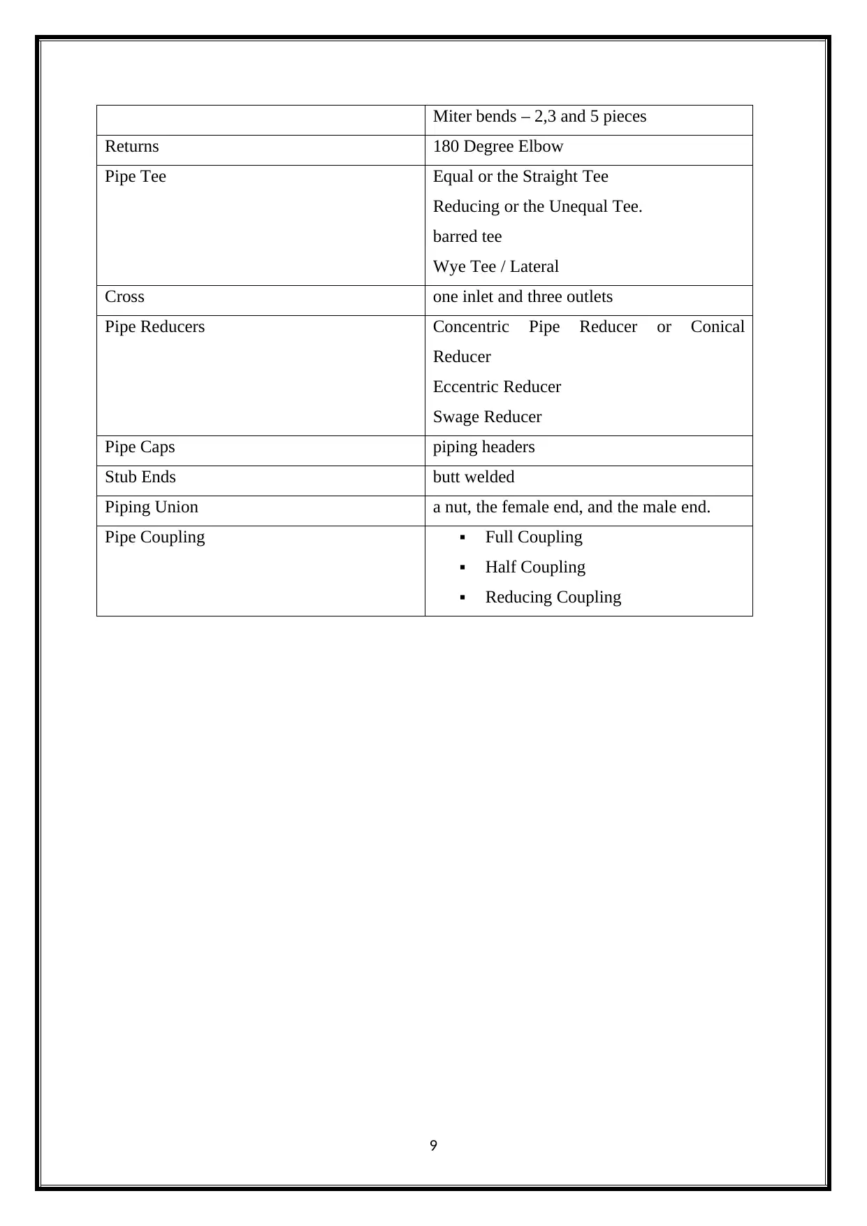
Types of fittings Specifications
Pipie Elbow 90 Degree elbow pipe
45 Degree Elbow pipe
Long radius Elbow
Short Radius Elbow
Pipe Bend 3D and 4D pipe bends
8
Miter bends – 2,3 and 5 pieces
Returns 180 Degree Elbow
Pipe Tee Equal or the Straight Tee
Reducing or the Unequal Tee.
barred tee
Wye Tee / Lateral
Cross one inlet and three outlets
Pipe Reducers Concentric Pipe Reducer or Conical
Reducer
Eccentric Reducer
Swage Reducer
Pipe Caps piping headers
Stub Ends butt welded
Piping Union a nut, the female end, and the male end.
Pipe Coupling Full Coupling
Half Coupling
Reducing Coupling
9
References
1. https://www.infona.pl/resource/bwmeta1.element.baztech-7df34284-ffaf-4ea8-9dbb-
476a9146149c/tab/summary
2. https://www.tandfonline.com/doi/full/10.1080/14733315.2018.1432840?
scroll=top&needAccess=true
3. https://www.researchgate.net/publication/
327017696_Effect_of_mechanical_ventilation_and_natural_ventilation_on_indoor_cl
imates_in_Urumqi_residential_buildings
Amoako-Attah, J. and B-Jahromi, A. (2016). The Impact of Different Weather Files on
London Detached Residential Building Performance—Deterministic, Uncertainty, and
Sensitivity Analysis on CIBSE TM48 and CIBSE TM49 Future Weather Variables
Using CIBSE TM52 as Overheating Criteria. Sustainability, 8(11), p.1194.
Gu, J., Jung, J. and Lee, K. (2012). Research on the Characteristics of the Light Trespass
using by RELUX Program According to the Spatial Position of the Road Lightings in
Residential Area Near Road. Journal of the Korean Institute of Illuminating and
Electrical Installation Engineers, 26(11), pp.1-8.
Hwang, I. (2018). Illan Nam, Democratizing Health Care: Welfare State Building in
Korea and Thailand, Palgrave Macmillan, 2015. Japanese Journal of Political Science,
19(01), pp.101-103.
Kotzen, B. (2010). Environmental Noise Barriers: A Guide to their Acoustic and Visual
Design, 2nd Edition. Noise Control Engineering Journal, 58(6).
Raynham, P. (2012). Book review: The Lighting Handbook 10th Edition, Reference and
Application. Lighting Research & Technology, 44(4), pp.514-515.
Yau, Y. (2012). Climate change implications for HVAC&R systems for a large library
building in Malaysia. Building Services Engineering Research and Technology, 33(2),
pp.123-139.
10
Secure Best Marks with AI Grader
Need help grading? Try our AI Grader for instant feedback on your assignments.
11
1 out of 11
Your All-in-One AI-Powered Toolkit for Academic Success.
+13062052269
info@desklib.com
Available 24*7 on WhatsApp / Email
Unlock your academic potential
© 2024 | Zucol Services PVT LTD | All rights reserved.