Project Report: Design of Grinding Wheel Attachments on Lathe Machine
VerifiedAdded on 2023/04/24
|8
|1747
|72
Project
AI Summary
This project report details the design and analysis of grinding wheel attachments for a lathe machine. The project aimed to design and fabricate grinding wheel attachments, maintain low production costs, and utilize Inventor software for simulation and analysis. The student, acting as team leader, focused on vibration absorption, attachment rigidity, and shaft deflection. Key aspects included selecting appropriate grinding wheels and motors, conducting experimental design matrix analysis, and addressing issues related to project accuracy and surface finishing. The project concluded with a review of material selection, testing, and simulation, highlighting the student's contributions to the design and analysis process.
CE 3.1 Project Information
Name of the project: Design of Grinding Wheel Attachments on the Lathe Machine
Location of the project: Please fill
Project Duration: Please fill
Organization: Please fill
Role and Designation during the time: Team Leader
CE 3.2 Project Background
CE 3.2.1 Characteristics of the project
Grinding operations are being performed to obtain and gain fin surface finishing only
after the performance of significant turning operations on a lathe machine to complete each
and every cylindrical work. It is majorly completed to obtain the required part dimensions to
be used in an assembly. Thus in the project of the grinding wheel attachments, I had
performed two distinctive operations within the same machine and this particular attachment
was properly designed. To efficiently verify this specific design, I had fabricated the
subsequent attachment. Furthermore, for the design rigidity as well as vibration damping, I
had to use the software of Inventor and then compared with the respective theoretical
calculation. The several parameters, which I had undertaken within the project were the
higher speed of work for 15 as well as that of the lower speed of 6. I had even chosen A-
60PV grinding wheel and outer diameter of 150 mm and the inner diameter of 20 mm. Thus,
I had proposed a compact design for the grinding wheel only after consideration of these
above provided specifications in the project.
Paraphrase This Document
Need a fresh take? Get an instant paraphrase of this document with our AI Paraphraser
CE 3.2.2 Objectives developed for the project
The project of Design of the Grinding Wheel Attachment on the Lathe Machine was
eventually carried out after considering a subsequent purpose to design as well as fabricate
the respective grinding wheel attachments on a lathe machine by involving proper software
deployment. After initiating this particular project, I had successfully developed few
objectives, which are given below:
To suggest a compact strategy and even construct a specific grinding wheel
attachments on the lathe machines.
To effectively design respective grinding wheel attachments only after the subsequent
consideration of typical criterion.
To properly maintain the low production as well as maintenance expenses to design
these grinding wheel attachments.
To use the software of Inventor to successfully simulate as well as analyze the
respective project on the lathe machine.
To setup this entire experiment for the purpose of making my project effective.
To contrast as well as investigate the several experimental outcomes with each
previous examination and then gain better solutions.
CE 3.2.3 My area of work
To work out over this project of Design of the Grinding Wheel Attachments on the
Lathe Machines; I was recruited as the team leader in this project. As, I had formerly worked
with several similar project kinds and thus this was quite easier for me to complete this
project work all by myself. The vibration absorption, attachment rigidity, deflection of
theoretical shaft as well as work pieces cylindricity were properly considered in this scenario
and hence I did not face any distinctive problem during the completion of this task. With my
core skills of complex problem-solving and the major concepts mechanical engineering, I had
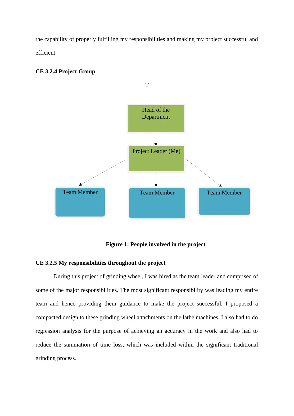
Head of the
Department
Project Leader (Me)
Team MemberTeam Member Team Member
the capability of properly fulfilling my responsibilities and making my project successful and
efficient.
CE 3.2.4 Project Group
T
Figure 1: People involved in the project
CE 3.2.5 My responsibilities throughout the project
During this project of grinding wheel, I was hired as the team leader and comprised of
some of the major responsibilities. The most significant responsibility was leading my entire
team and hence providing them guidance to make the project successful. I proposed a
compacted design to these grinding wheel attachments on the lathe machines. I also had to do
regression analysis for the purpose of achieving an accuracy in the work and also had to
reduce the summation of time loss, which was included within the significant traditional
grinding process.
⊘ This is a preview!⊘
Do you want full access?
Subscribe today to unlock all pages.

Trusted by 1+ million students worldwide
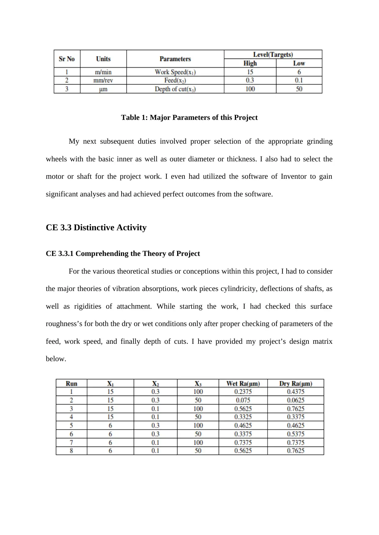
Table 1: Major Parameters of this Project
My next subsequent duties involved proper selection of the appropriate grinding
wheels with the basic inner as well as outer diameter or thickness. I also had to select the
motor or shaft for the project work. I even had utilized the software of Inventor to gain
significant analyses and had achieved perfect outcomes from the software.
CE 3.3 Distinctive Activity
CE 3.3.1 Comprehending the Theory of Project
For the various theoretical studies or conceptions within this project, I had to consider
the major theories of vibration absorptions, work pieces cylindricity, deflections of shafts, as
well as rigidities of attachment. While starting the work, I had checked this surface
roughness’s for both the dry or wet conditions only after proper checking of parameters of the
feed, work speed, and finally depth of cuts. I have provided my project’s design matrix
below.
Paraphrase This Document
Need a fresh take? Get an instant paraphrase of this document with our AI Paraphraser
Table 2: Experimental Design Matrix with the Surface Roughness for both Wet as well
as Dry Conditions
While selecting the grinding wheel, I had to check the various parameters, which will
be appropriate for this application and would not be a failure under any circumstance. I have
selected A-60PV grinding wheel attachments and outer diameter and inner diameter were 150
mm and 20 mm and respective thickness was about 12.7 mm and I selected AC motor in this
project. I selected 2950 rpm speed and power of 1 HP. Furthermore, I have chosen the 50 Hz
frequency, 415 V voltage and 1.8 AMP current. I also had to choose the standardized shaft
with the appropriate length or diameter with lathe by the simplified turning operations. I also
had to ensure that project shaft is not vibrating under any circumstance. For the base plate or
frame, I had considered the respective thickness of 2 cm and the total length of 52 cm.
Regarding the thickness of base plate, I had considered 0.5 cm and the height of 15.75 cm.
CE 3.3.2 Engineering knowledge and skills applied in the project
I had used my significant skill of mechanical engineering to successfully complete
this project. For the purpose of calculating the respective displacement, I had to consider my
core knowledge of horizontal as well as vertical displacements. I even had utilized my major
skill for the design calculations as well as mechanical specification. Regarding the software
deployment, I had to use software package of Inventor for executing my project efficiently
and effectively. With my team leading skills, I was able to lead the entire project team
properly.
CE 3.3.3 Accomplishment and Task Performed
To complete the project, I had obtained the significant project objectives, however
few of significant and important issues were needed to be emphasized to generate accuracy of
the 20 microns and fine surface finishing. I even had to consider the particular information
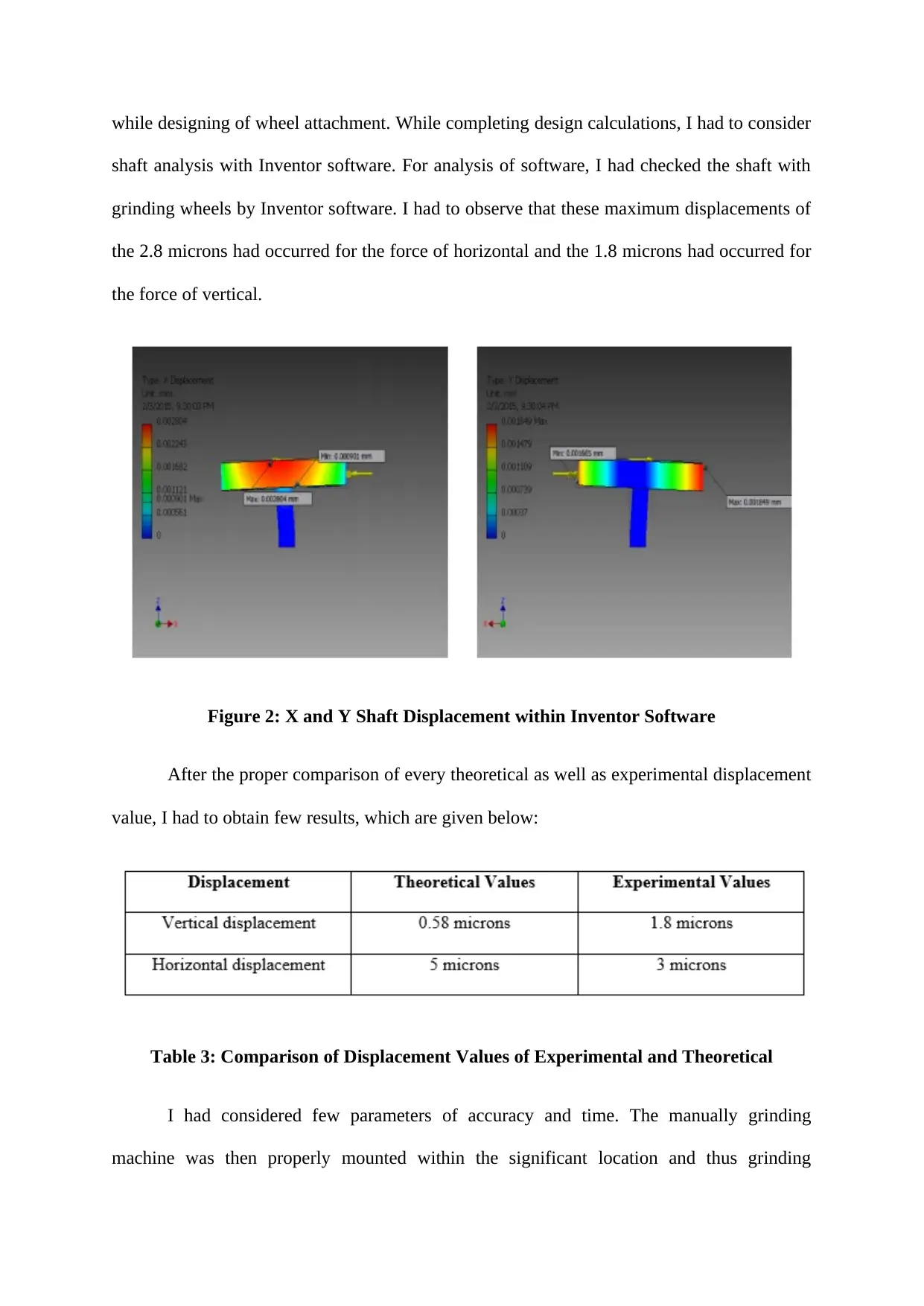
while designing of wheel attachment. While completing design calculations, I had to consider
shaft analysis with Inventor software. For analysis of software, I had checked the shaft with
grinding wheels by Inventor software. I had to observe that these maximum displacements of
the 2.8 microns had occurred for the force of horizontal and the 1.8 microns had occurred for
the force of vertical.
Figure 2: X and Y Shaft Displacement within Inventor Software
After the proper comparison of every theoretical as well as experimental displacement
value, I had to obtain few results, which are given below:
Table 3: Comparison of Displacement Values of Experimental and Theoretical
I had considered few parameters of accuracy and time. The manually grinding
machine was then properly mounted within the significant location and thus grinding
⊘ This is a preview!⊘
Do you want full access?
Subscribe today to unlock all pages.

Trusted by 1+ million students worldwide
procedure was being considered. Thus, I had checked that the grinding attachment had
consumed less time in comparison to the manually grinding procedure.
CE 3.3.4 Identified issues and their solutions
3.3.4.1 Issues
The most significant issue, which I have faced in this project was while consideration
of project accuracy. Previously, I have undertaken maximum accuracy of surface of 10
microns and thus this was not producing appropriate outcomes in my project. Another
important technical difficulty, which I had faced in the project was while checking surface
finishing. This ratio undertaken was 1:10 in the work for the oil to the water and hence this
roughness of surface was not correct for the wet as well as drying grinding conditions.
3.3.4.2 Solutions
To solve my first issue, I had to come up with an idea to use 20 microns to attain high
accuracy in surface as soon as I had compared the attachment of grinding wheel over lathe
machine to the respective manual process of grinding. Regarding the next technical difficulty,
I recognized my problem and next utilized coolent of the ratio of 1:20 for the oil to the water
and thus this roughness of surface was being achieved within the range of 0.26 until 0.8 in
wet grinding process and range of 0.14 until 0.45 in drying grinding condition.
CE 3.3.5 Plan to produce creative and innovative work
My most significant or important plan in the work was to produce an innovative work
by effectively working altogether. I also subdivided the complete works properly and
individual task was eventually and perfectly executed.
Paraphrase This Document
Need a fresh take? Get an instant paraphrase of this document with our AI Paraphraser
CE 3.4 Project Review
CE 3.4.1 Project Overview
I have to successfully order the several materials required. The material testing was
being done properly to energize circuit. Finally, I had successfully utilized my mechanical
engineering skills and the software of Inventor to simulate this project work.
CE 3.4.2 My Contribution to work
I had to provide guidance to my team members and to propose a compacted design for
grinding wheel attachments on the lathe machines, as I was selected as a mechanical
engineer. Furthermore, I also evaluated several project parameters such as grit, structure,
abrasives, bond, and grade and then completed this project simluation with the software of
Inventor.
1 out of 8
Related Documents
Your All-in-One AI-Powered Toolkit for Academic Success.
+13062052269
info@desklib.com
Available 24*7 on WhatsApp / Email
![[object Object]](/_next/static/media/star-bottom.7253800d.svg)
Unlock your academic potential
Copyright © 2020–2025 A2Z Services. All Rights Reserved. Developed and managed by ZUCOL.


